 f4hdk
f4hdkThe detailed description in inside 5 blog posts, 5 chapters:
0%
0%
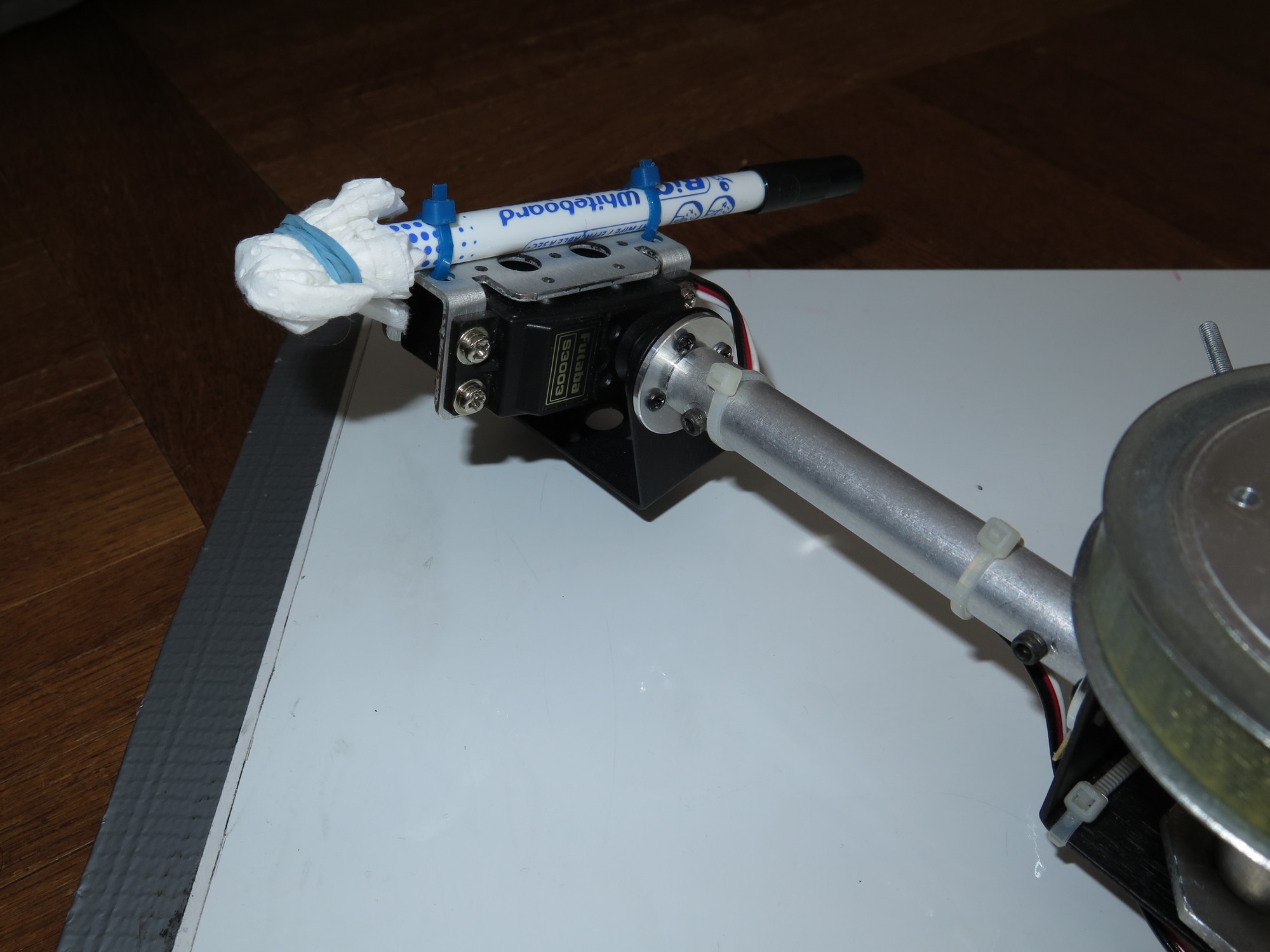
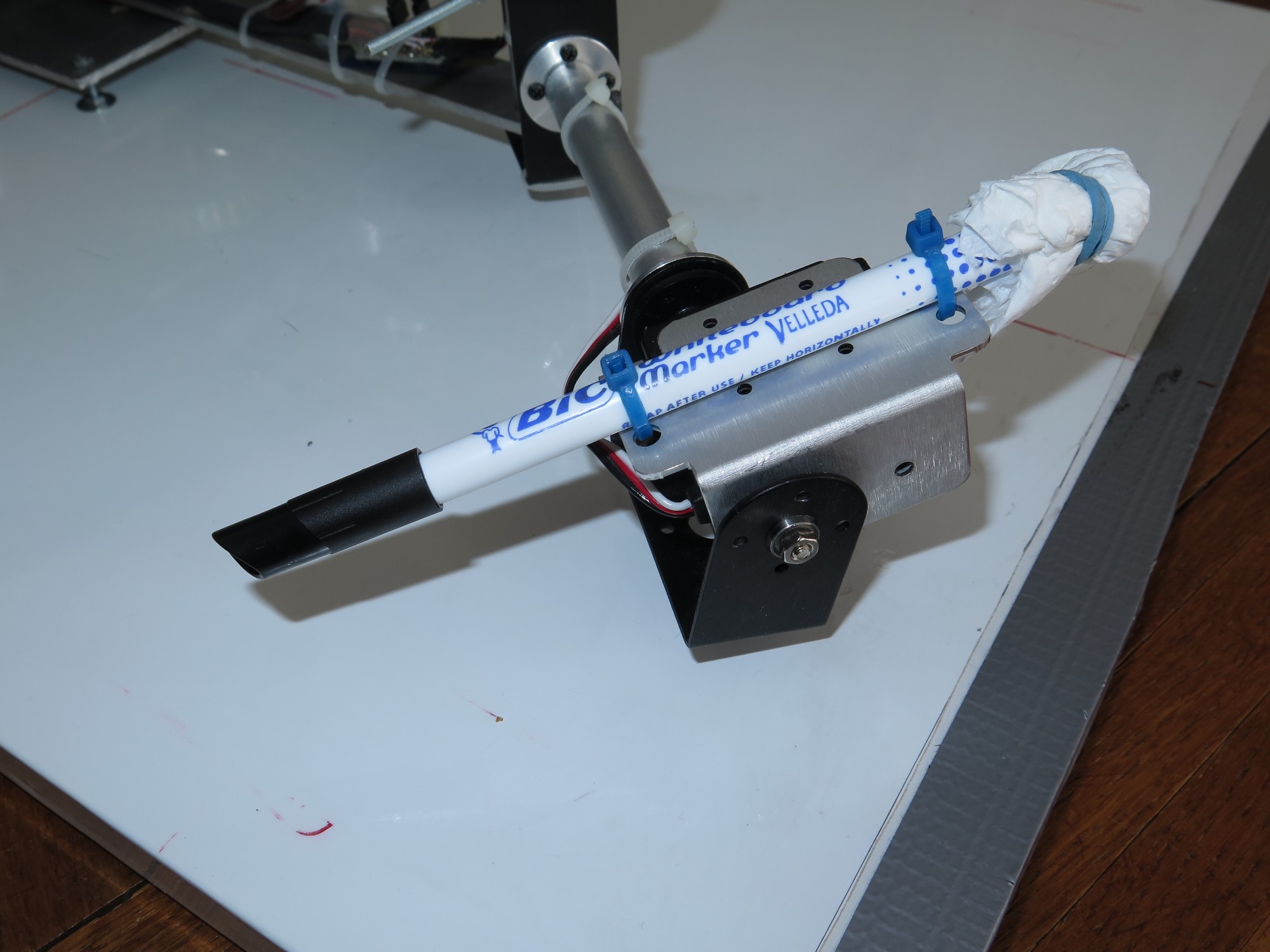
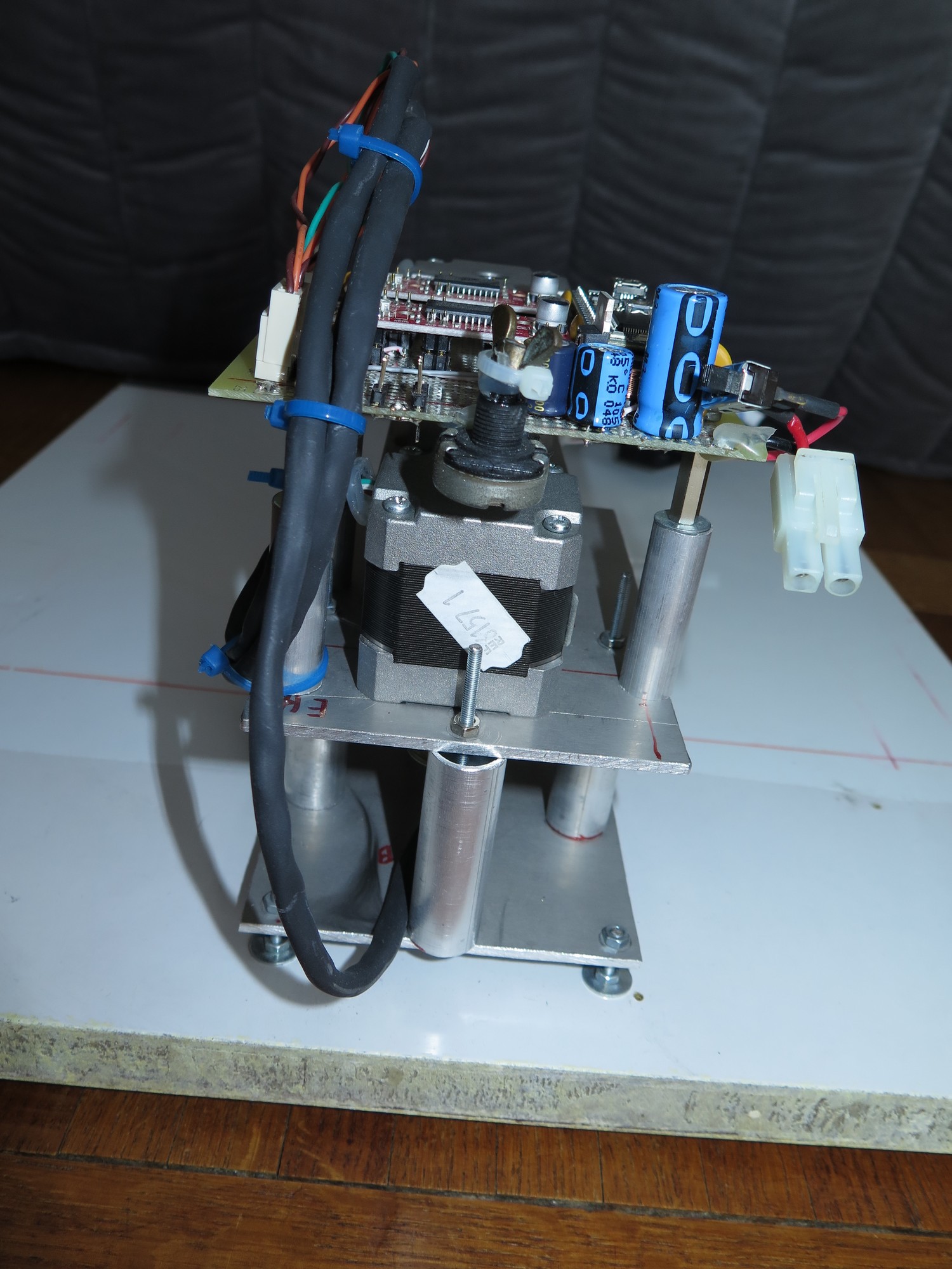
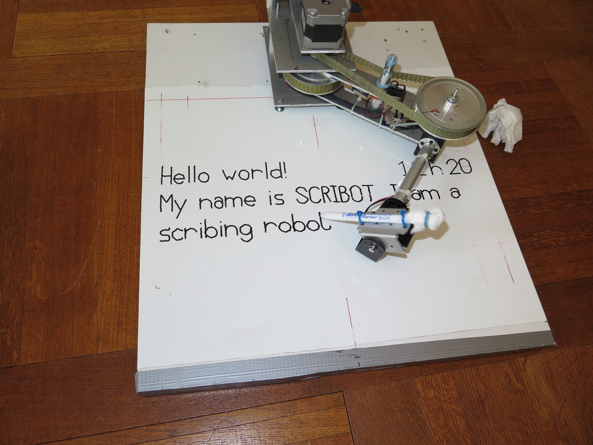
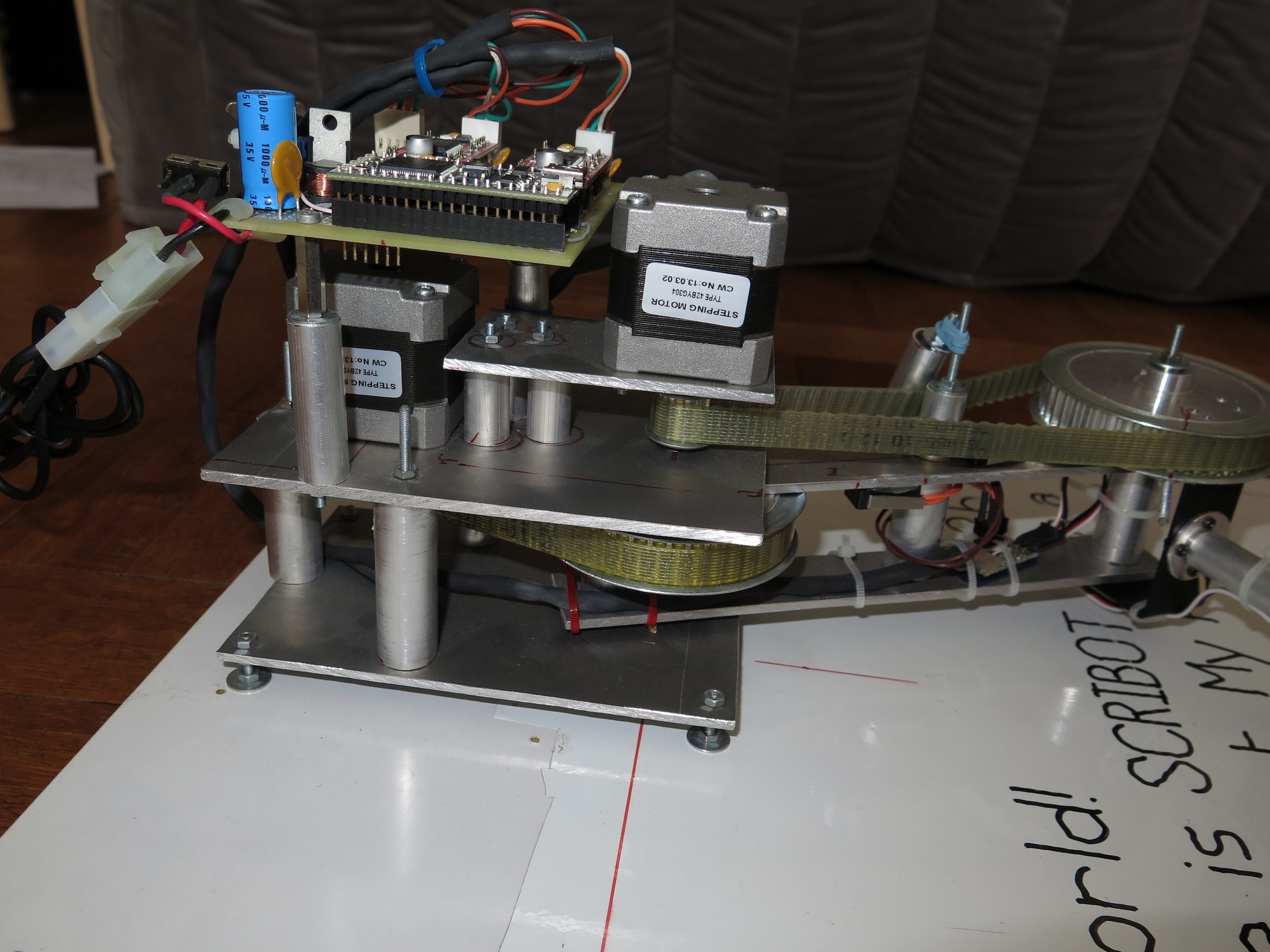
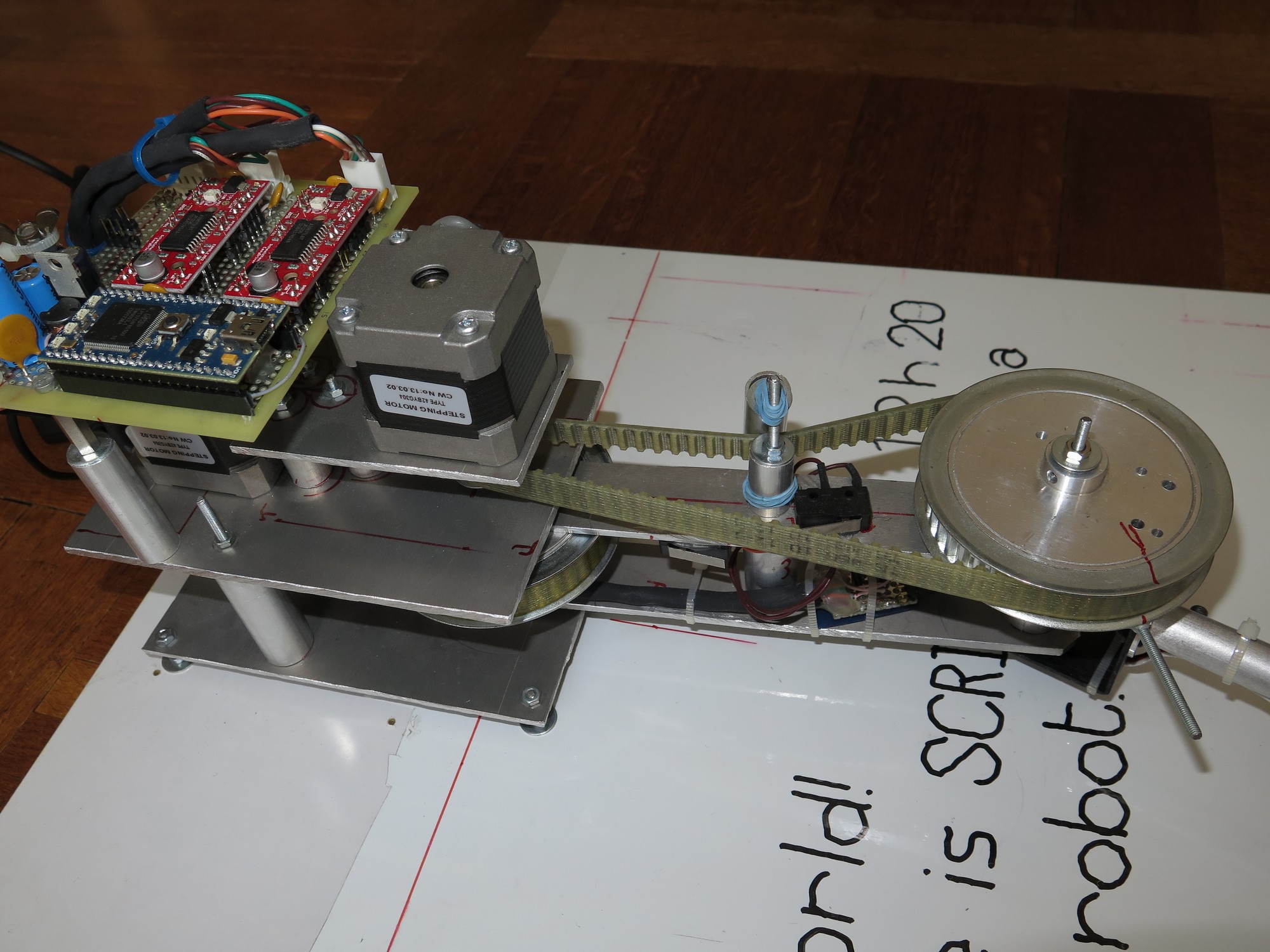
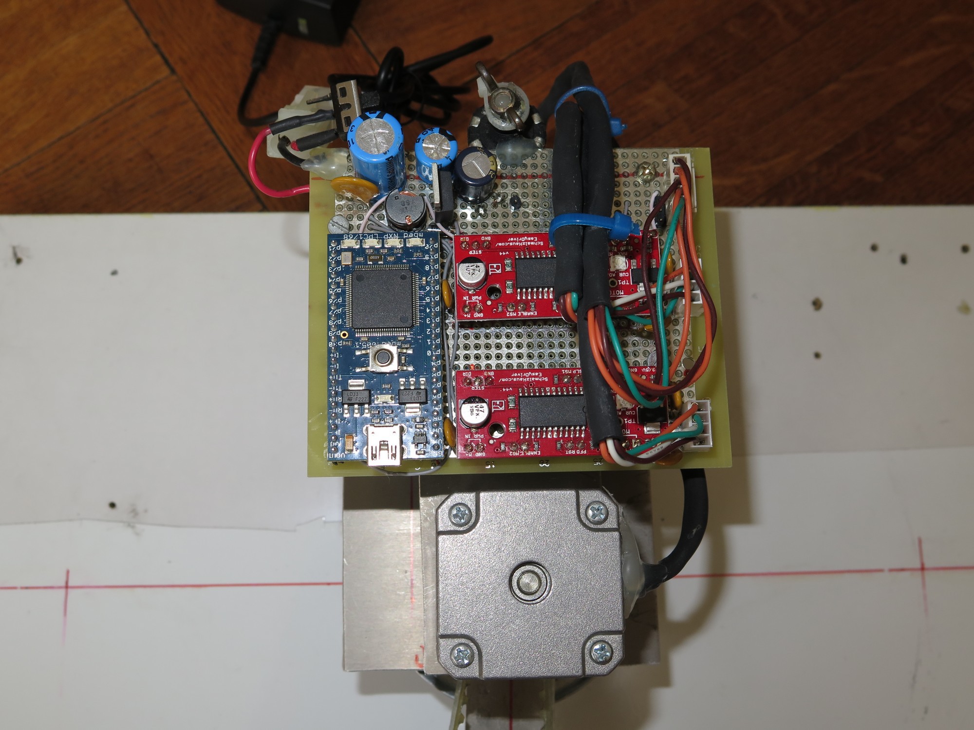
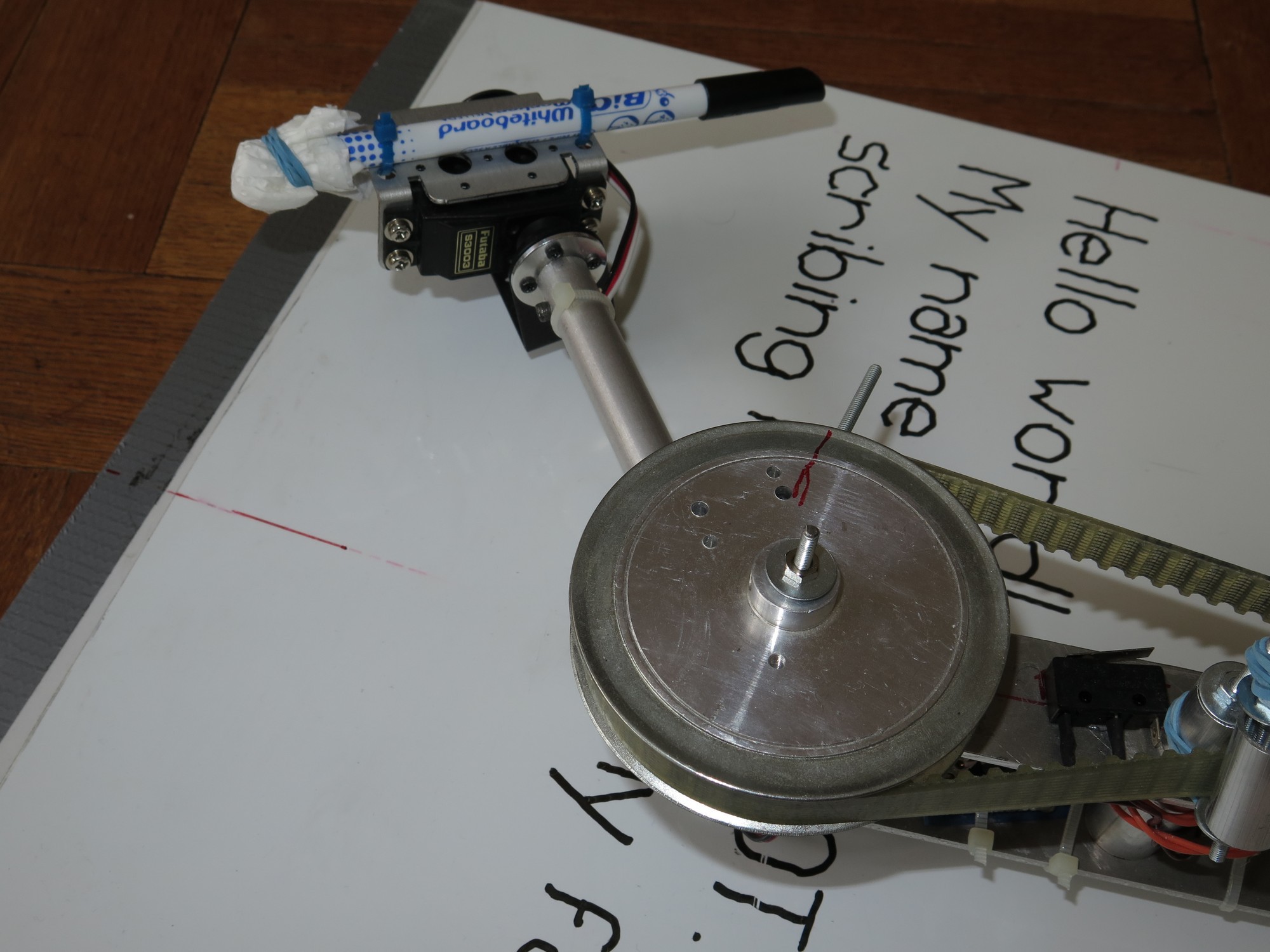
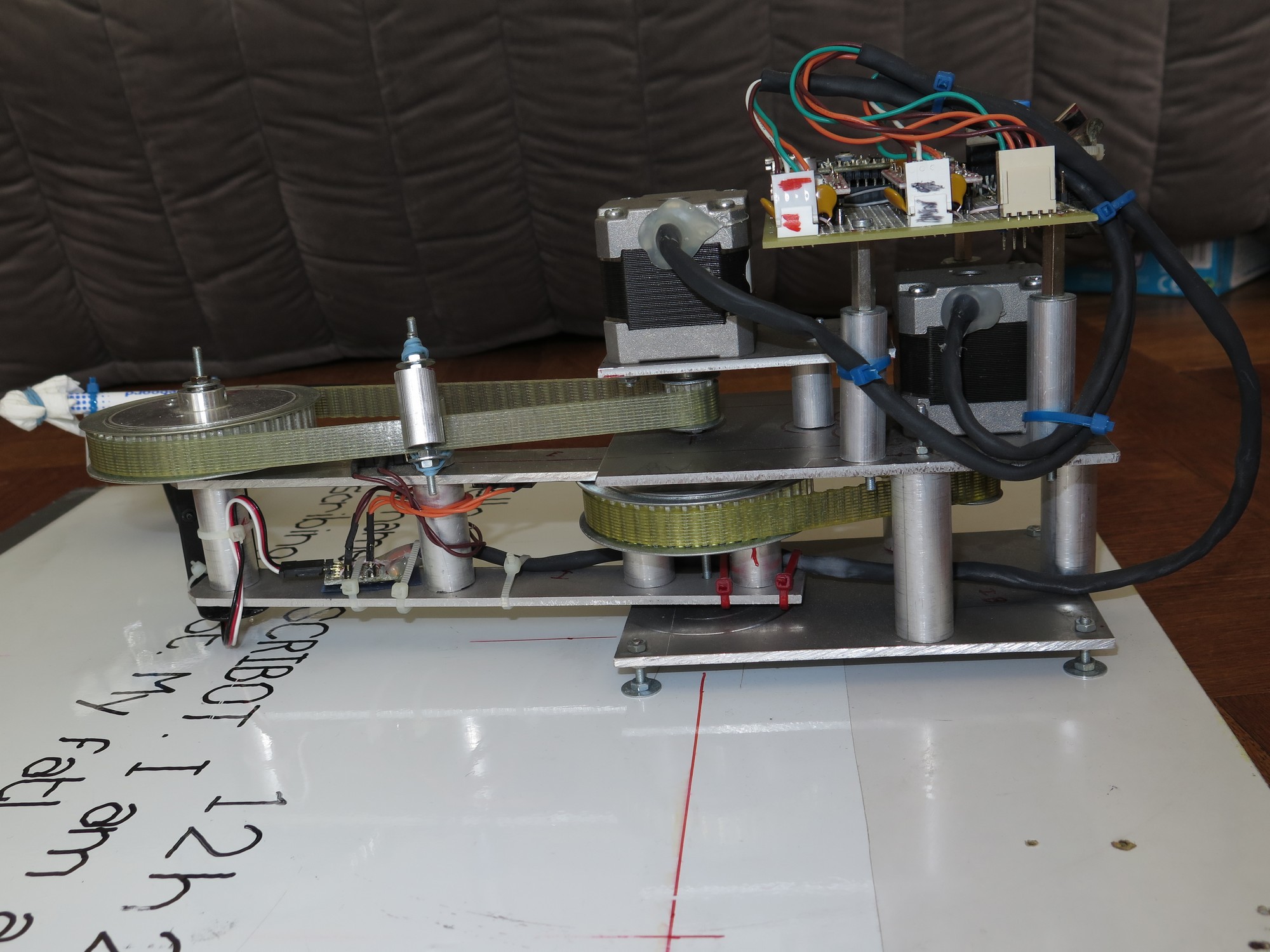
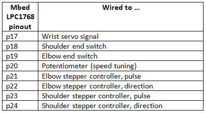
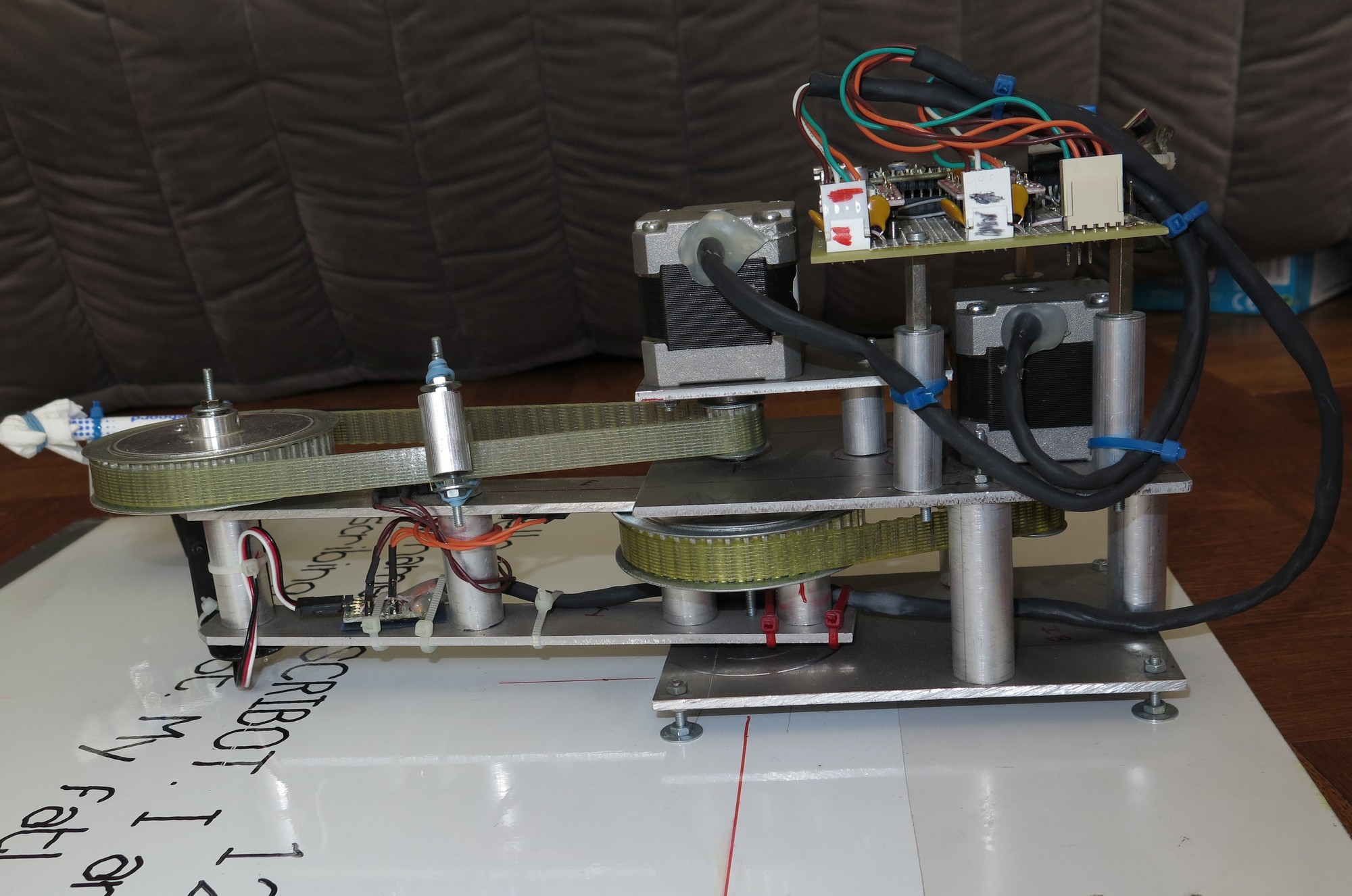
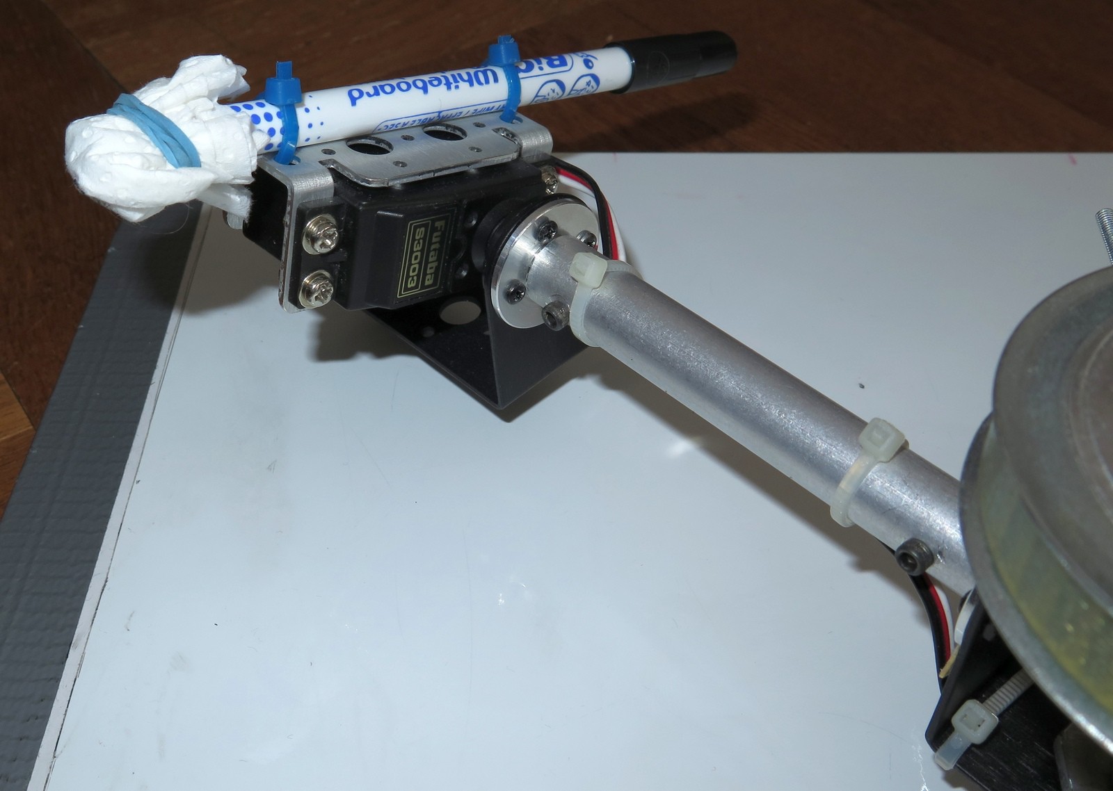
Scribing Robot
Writing on a whiteboard with stepper motors
Become a Hackaday.io member
Already have an account? Log in.
Just one more thing
To make the experience fit your profile, pick a username and tell us what interests you.
Pick an awesome username
hackaday.io/
Your profile's URL: hackaday.io/username. Max 25 alphanumeric characters.
Pick a few interests
Projects that share your interests
People that share your interests


 Petar Crnjak
 Danny FR
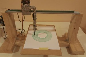

 Chris
Chris
Thank You so much for given the helpful and informative maths blog. Please explain further about trigonometry and maths formulas.
https://theshadowapk.com/