Close
0%
0%

LoFi

LoFi is a very low cost ($5), small, auto-transmitting module. Preassembled and preprogrammed. Simply attach to your appliances or projects!

Similar projects worth following
Like many hackers and hobbyists, we dream of a smart home. Although there are third-party transceiver modules and data loggers on the market, they are too expensive and complicated to deploy in volume.

LoFi is a very low cost ($5), small, auto-transmitting module. All you need to do is to attach the modules to interesting appliance circuit points or sensors throughout your home and garden. The data arrives on your PC or can be sent to the Internet with a WiFi hotspot.

No programming, no protocols to learn, and no carrier boards for you to make. Just attach!

Using your desktop or laptop, you can set trigger levels on individual modules to tell them when to transmit. For example, send an update when the voltage changes by more than 1 V on the vibration sensor near the garage door opener. You can also set the module on a timer, such as hourly on your garden monitor.

The possibilities are endless!

SENDER

The sender is compact (1.25 sq. inch) and operates from 1.8 to 5.5 V. The module consists primarily of an Atmel ATtiny84A which monitors the inputs and outputs the data. A red and green LED provides visual status.

The sender module has:

  • Five analog inputs with configurable triggers
  • Digital trigger
  • Built-in temperature sensor
  • Battery voltage measurement
  • Optional CR2032 coin cell holder
  • Optional pushbutton to manually activate data transmission

CONFIGURATION

Without any programming knowledge, the sender module can be configured to transmit:

  • On power up
  • When any analog input goes above a certain value
  • When any analog input goes below a certain value
  • When any analog input changes by more than a certain amount
  • Periodically from 1 second to 18 hours

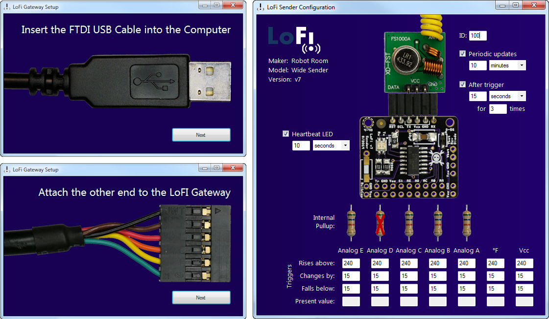
Configuration is accomplished using a laptop or desktop connected via a standard FTDI serial cable.

LOW COST

The sender costs only $2.43 in parts (qty 1000) or $3.50 (qty 10). Think of all the things you can monitor at that price -- in the garage, basement, garden, kitchen, or bedroom.
LOW POWER

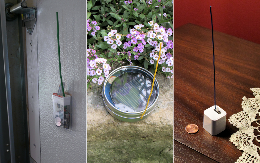
The sender uses only 18 µA on average. This means it can be installed in small places while running on a coin cell, or can be virtually maintenance free with a pack of AAs.

CONNECTEDNESS

The LoFi gateway listens to all of the senders and uploads the data to a PC or to the Internet. LoFi is compatible with data.sparkfun.com (aka Phant), a free open-source Internet repository. As demonstrated in the Semifinals video, you can connect LoFi to the Internet in under 2 minutes.

INTERFACE

The interface couldn't be more easy. On the sender, simply solder sensors to the standard 0.1-inch pitch holes. No programming necessary. On the PC, the software walks you through each connection step and lets you modify device configuration in a friendly UI.
Non-proprietary output means you can use all of the repository tools written for Phant (or for the JSON, XML, tab values it provides). The output from the Gateway to the PC is tab-delimited plain text, so you can log it in a terminal program or write your own software regardless of OS.

LEARN MORE

Battery Life Expectancy (1 year on coin cell, 10 years on AA)

Message Delivery Rate (>95% success rate)

Dealing with Static: Auto Gain Preamble and Error Correction

LoFi as a Solar-Powered Weather Station (temperature and light levels)

LoFi Detecting Garage Door State (tilt ball switch)

Artist Rendition of Productized Look and Feel (contest requirement)

Sender Schematic

Good Things Come in Small Packages (fitting into a pill bottle and iPhone charger)

  • 1 × C1 Capacitor 10µF 16WV (CC1206ZKY5V7BB106)
  • 1 × IC1 Microcontroller, SOIC, ATtiny84A (ATTINY84A-SSU)
  • 1 × J1 Connector, 6-pin right-angle female socket (PPPC061LGBN-RC or 801-87-006-20-001101)
  • 1 × LED1 Status LED, 1210, bicolor (LTST-C155KGJRKT)
  • 2 × R1, R2 Current-limiting resistor, 220Ω 5% (RC1206FR-07220RL)

View all 9 components

  • Did I Leave the Stove On?

    David Cook09/28/2014 at 20:05 0 comments

    Have you ever left the house and had that little voice in your head say “Did I remember to turn off the stove?" Or maybe you're concerned about a loved-one living independently. With LoFi, you can eliminate needless worry.

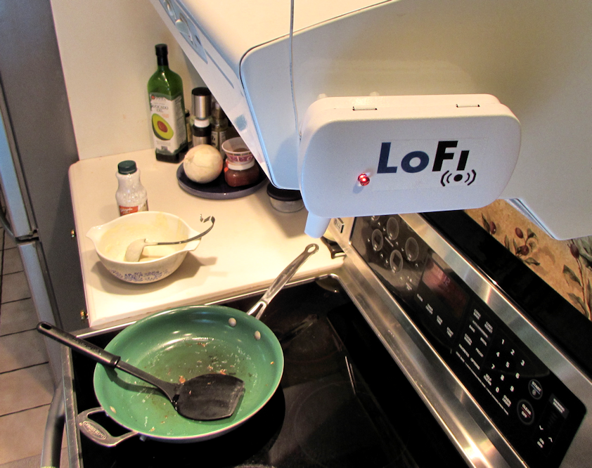
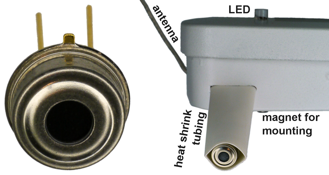
    Here is an example application where LoFi wirelessly monitors a stove using an adjustable heat detector. The steel casing is magnetically mounted so that it is out of the way, but does not require permanent installation.

    You can see this in action towards the end of the Semifinals video.

    TECHNICAL DETAILS

    Contactless temperature sensors provide an opportunity to instrument major appliances without opening or altering them. It is possible to connect a wireless transmitter to the LEDs on a modern oven display to determine if the stove is active. However, a less invasive technique is to simply measure the temperature externally using infrared.

    The Melexis infrared sensor (MLX90614) sees -70C to +380C. It is as simple as aiming the sensor at the stove top and measuring the temperature. LoFi transmits changes in the analog value, and can trigger transmissions on either those changes or a digital trigger pin.

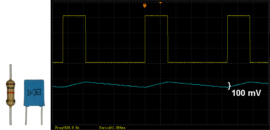
    The Melexis thermal sensor can be read with either I2C or PWM (app note). LoFi is designed for analog inputs. To convert the Melexis PWM output to analog, attach a 10 kilohm resistor and 0.1 μF capacitor to the output pin.

    For user friendliness, I wanted an adjustable “on" threshold and an indicator light. Because only one input pin is needed by LoFi, it would have been cheapest, smallest, and easiest to modify the code to have LoFi's ATtiny chip perform the comparison operation and light the LED with the spare pins.

    For the sake of being a purist, I instead chose to create an interface board containing a comparator, so that LoFi would still be considered 'stock'. That is, this was an opportunity to document a solution for people that aren't comfortable with programming.

    The TLV3702 was chosen because it works down to 2.5 volts. C2 and R2 convert the IR sensor PWM to analog. R3 is the adjustment threshold for determining when the stove is 'on'.

    Below is the implementation of the circuit. Again, the comparator is only necessary if you don't want to modify the LoFi source code.

    There are a wide variety of interesting things to monitor in a home. With LoFi, the price is low enough to make it affordable.

  • You've Got Mail!

    David Cook09/17/2014 at 04:39 0 comments

    A wireless mailbox notifier lets you know when the postal mail has arrived in your mailbox. This can be particularly helpful if your mailbox is not immediately adjacent to your front door.

    The mailbox notifiers I've seen usually rely on detecting when the mailbox lid is opened (hall effect sensor or tilt switch) or when a person approaches (motion sensor). Those are fairly successful methods -- but I didn't want to repeat what other people have already done. Also, those methods don't take into account whether mail is waiting or instead the homeowner simply triggered the lid sensor by anxiously checking their empty mailbox.

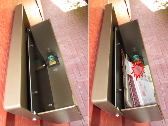
    Instead, I'd like to check for the presence of something in the box. A hacked postal scale would be highly effective, but would be awkward to fit. So, I'm going to use a reflected sensor: emit infrared light and measure the amount that returns. A white envelope or glossy magazine reflects significantly more light than an empty box. And, because LoFi transmits analog values, a threshold doesn't need to be tweaked between 'detect' and 'non-detect' states.

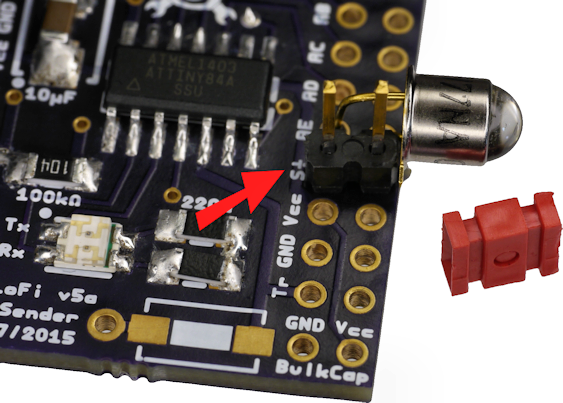
    Here's the schematic: (which is attached to LoFi)

    The 22 kilohm resistor forms a voltage divider with the phototransistor. A change in light (either due to sunlight entering due to the box being opened or due to reflection off of mail) changes the conductance of the phototransistor, and thus the division of voltage. That voltage is fed into a LoFi input.

    Two infrared emitters (LEDs) are placed in series with a current-limiting resistor to provide a light source. The second emitter is powered for 'free', as it simply uses power that otherwise would have been burned off in the resistor. On average, about 20 mA will flow.

    GREAT SCOTT!

    Twenty milliamps will drain the battery pack in less than a week! I thought LoFi was supposed to be low power?

    LoFi has a pin that provides GND only when the sensors are being read. Thus, when LoFi is sleeping (98% of the time), the emitters are off. Therefore, the AA pack will last years.

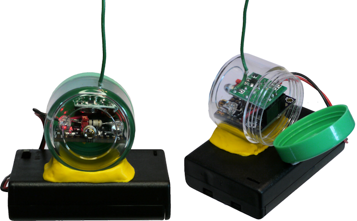
    For the case, I found some small plastic jars with colorful screw-on lids (Amazon B00523WBK2). This is attached with yellow Sugru.

    HOW WELL DOES IT WORK?

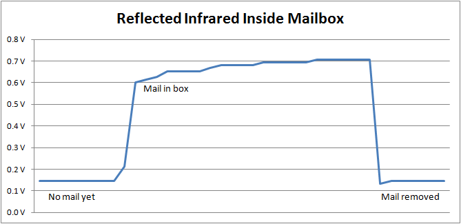
    As you can see below, the infrared reflective sensor detects mail very well. Over time, it will be interesting to see what different bunches of mail look like. “Either we just received a ton of mail, or one very glossy white envelope."
    I'm not sure why the detection increases slightly over time when staring at mail. Either the mail is settling or the phototransistor has both a fast and slow component to its detection properties. Perhaps it follows a curve like a capacitor?

    I did encounter one issue, which is that 433 MHz transmitter was completely shielded inside the metal box. I managed to snake the antenna out one of the bottom drain holes, after enlarging the hole slightly with a drill. Fair warning, you may need to seek permission from your spouse and homeowners association. ; )

  • Gateway

    David Cook09/17/2014 at 02:59 0 comments

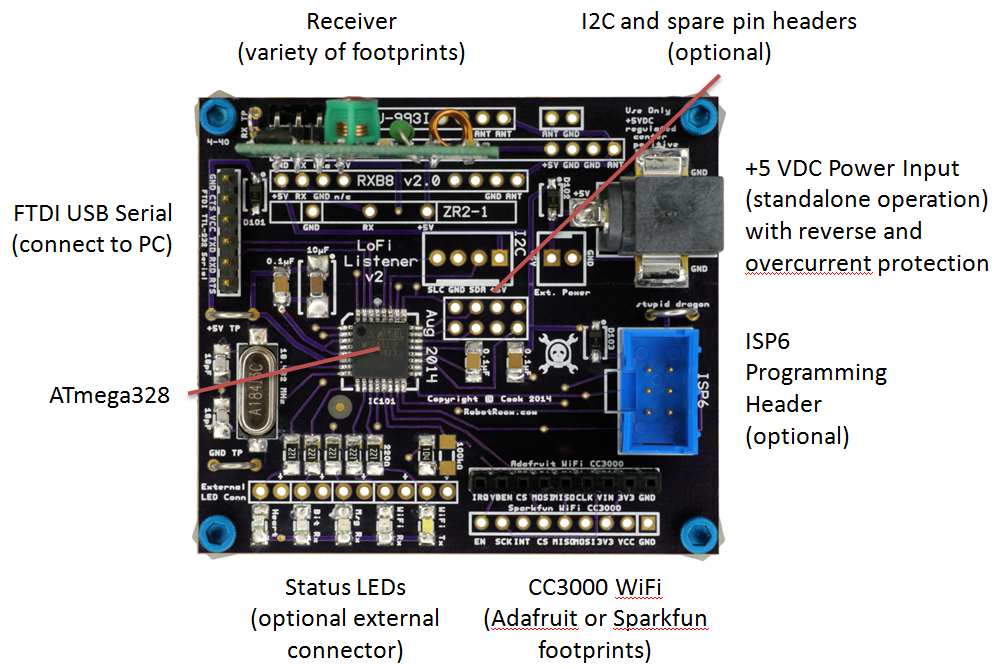
    The gateway listens to one or more senders and passes the data to a PC, or via WiFi to the intranet/Internet. This allows you to collect data locally or with a server.

    The gateway consists primarily of an Atmel ATmega328 microcontroller that reads the 433 MHz receiver and writes to the FTDI serial cable and CC3000 Wi-Fi board.

    Below you'll find the schematic. It begins with Schottky diodes for reverse battery protection and to allow multiple power source to be connected at the same time without affecting each other. This is followed by PPTC self-resetting circuit breakers for overcurrent protection. Finally, a Zener diode provides overvoltage protection. Because most people will only own one gateway, the extra cost of those protection parts is not a significant amount compared to an overall system.

    Notice that most of the pins are not connected to onboard components. Because the purpose of this board is to route messages, most of the pins lead to external connectors. Many spare pins are available, as this chip was selected for its speed, RAM, and surface-mount package.

    You can examine the PCB and Gerbers in the LoFi-PCB-Layouts.

  • Productized Artist Rendition

    David Cook09/14/2014 at 21:11 0 comments

    A requirement of TheHackadayPrize Semifinals is to post concept art for the productized look and feel of the project.

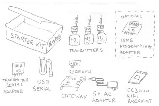
    The initial release of LoFi is primarily aimed at the hacker and electronic enthusiast community. Therefore, the first official product would likely be a starter kit.

    The starter kit would include all of the parts needed to set up an entire system. A reduced starter kit could drop the AC adapter and WiFi board, for customers that only want to connect to a PC. A deluxe starter kit could include a variety sensors and a precision calibration board.

    TURN-KEY PRODUCT

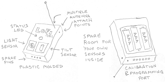
    Some people prefer to avoid handling the electronics or providing their own cases (even if only fished from the recycling bin). For those customers, an injection molded case prepopulated with light and tilt sensors would be preferable.

    The produce would take three AAA batteries to provide a long lifespan. A less expensive edition might exclude the spare pins and programming port.

    TINY TURN-KEY PRODUCT

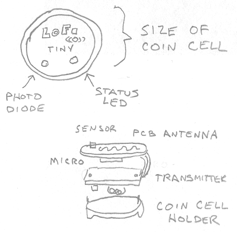
    As you can see in an earlier post, LoFi fits nicely in space spaces and can operate only a single coin cell. However, it can be tedious hand-wiring a small device. Therefore, it would be awesome for someone to manufacturer LoFi in a coin-cell sized case.

    This would allow anyone to use LoFi in small spaces.

  • Good Things Come in Small Packages

    David Cook09/02/2014 at 05:01 0 comments

    I’m experimenting with some novel enclosures for various installations of LoFi around the house and yard. I need to make an impact for the stage 3 judging.

    I ordered some more m&m’s candy tins, because they are an excellent size and have a clear top window. When you buy them, you can customize the candy pieces with logos and writing. So, I used the Hackaday Prize logo.

    LOFI in an IPHONE CHARGER

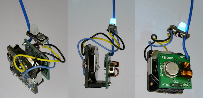
    I appreciate the industrial design talent at Apple. Here is LoFi inside of a standard Apple power adapter, which is approximately 1 inch cubed (25 mm). In the USB slot, a small panel holds a light sensor, an ice cube LED, and the antenna. Yes, it really works.

    The main board holds the CR2032 coin cell and has a standard 0.1 inch header for the transmitter and accessories. There is enough room leftover in the center for additional sensors.

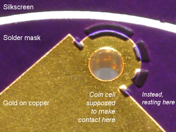
    LoFi runs for over a year on a single coin cell. Although I usually use a plastic holder, metal holders are cheaper and use less space. I designed a LoFi board with pads on the back for the ground terminal of the cell, and then bent the metal holder tabs around to the front of the board to attach the positive terminal.

    Unfortunately, I made a mistake. Upon inserting the coin cell, nothing happened! I checked my connections, looked for shorts, and even wrongly suspected the new ultra low dropout diode.

    The problem turned out to be my failure to account for the height of the solder mask. You see, the solder mask goes on top of the copper layer, and thus is slightly higher. The back of the coin cell was resting on the solder mask and not making contact with the pads on the back of the board. Applying a thin layer of solder to the pads raised it up enough to make contact.

    LOFI in a TUBE

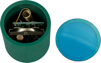
    I have a really interesting application where LoFi needs to fit inside of a 1-inch circular tube, rather than 1-inch square. The tube was machined from a green medical grade Delrin/acetal block.

    As you can see, LoFi managed to squeeze inside. A blue lens is machined to fit on top.

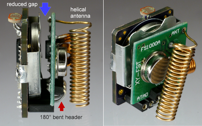
    To make LoFi fit in the smaller space, I needed to insert a longer header in the front of the transmitter and bend it back 180 degrees (see red arrow below). However, this would not be necessary in a production device, as you'd use a smaller connector. Anyway, bending the connector allows the socket to overlap the bottom of the board and close the gap (blue arrow). There is enough room in the tube to fit a helical antenna – with the accompanying reduction in range, of course.

    LoFi can now fit into a standard prescription pill bottle. A vibration sensor (added after the photos were taken) detects when someone is opening the bottle. The light sensor with the blue filter detects a significant change in brightness compared to when it was within the orange bottle.

    From this prototype, I determined that a pushbutton switch recessed in the side of the tube would be superior, as it would detect that the cap had been removed (rather than the bottle just shaken) and it would work in darkness.

  • Outdoor Temperature Monitor

    David Cook07/20/2014 at 03:13 2 comments

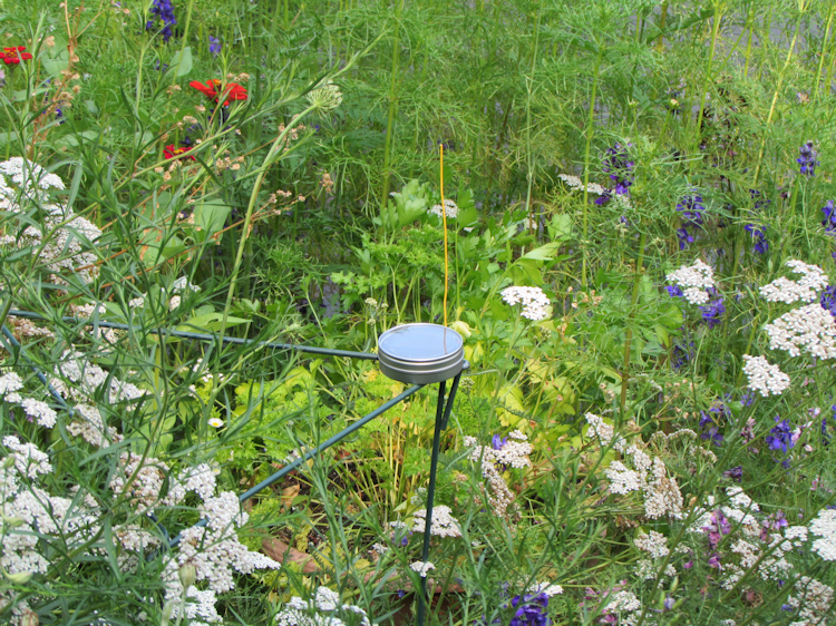
    In the previous logs, I've shown LoFi in the remote corner of the basement and in the garage. Now, LoFi ventures outside to the garden to measure temperature and light levels.

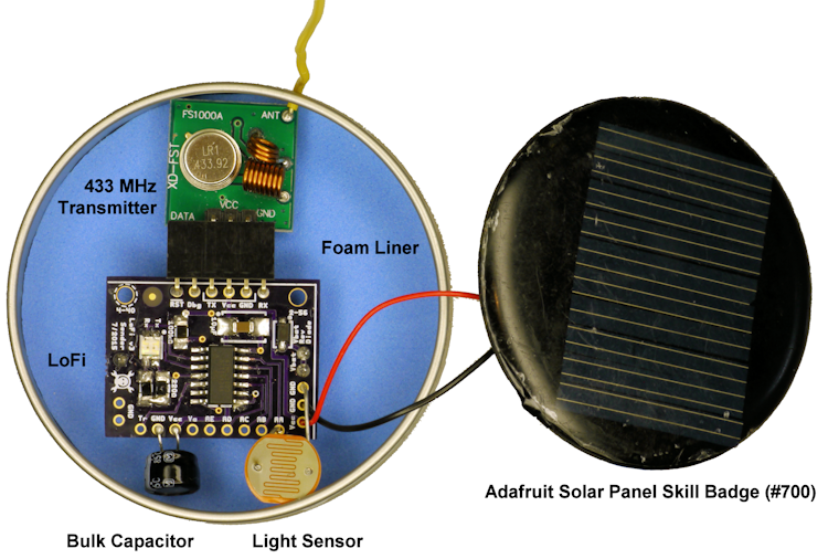
    A 'My M&M' silver favor candy tin (intended for weddings or parties) is the perfect size container for LoFi, the AM transmitter, a solar panel, coin cell (underneath the PCB), and various sensors. A clear lid permits light but blocks bugs, dirt, and hopefully rain. The transmitter antenna wire sneaks out the side through a #54 drill hole.

    A foam liner was added to the candy tin to avoid electrical shorts. Even though the container has a non-conductive coating to avoid contaminating the candy, I've been burned by scratched or worn areas in the past.

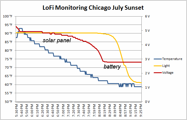
    When there is adequate sunlight, the solar panel powers the device. This solar panel was chosen because it fits so well, and provides the maximum voltage with good current. At full sunlight, the panel likely exceeds the ATtiny 5.5 V operating limit, but will stay under the absolute maximum of 6 V and has some voltage dropped by a Schottky reverse-protection diode.

    The ATtiny internal temperature sensor and voltage reference are 'no-cost' inputs. An added photocell provides brightness data, and was selected to be sensitive to conditions after the solar panel yielded to the backup battery.

    With wireless, it is nice to get immediate readings rather than logging to a flash as I have had to do in past experiments: http://www.robotroom.com/Weather-Station.html

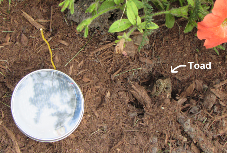
    This was not my first choice of locations for LoFi, but I discovered that a spot of land was already claimed by a toad in a hole.

  • Garage Door Monitor

    David Cook07/14/2014 at 01:22 2 comments

    An example usage of LoFi is to monitor when the garage door opens and closes, as well as when the garage's interior light has been left on.

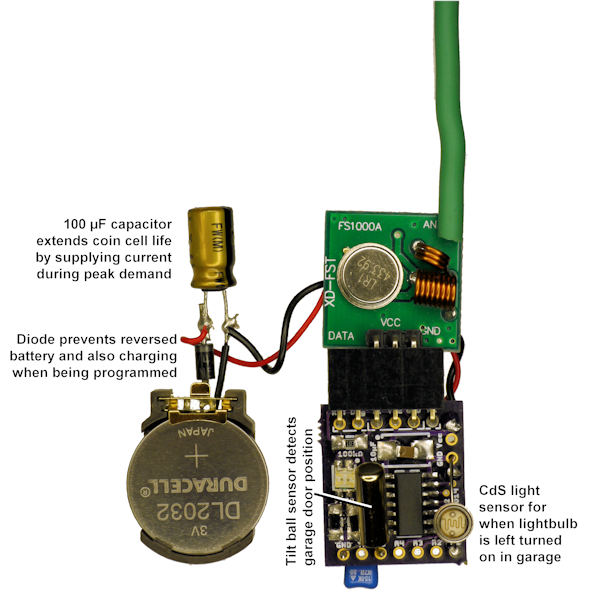
    LoFi is designed to perform such tasks with minimal added parts and no programming. However, Ralph Doncaster (Nerd Ralph) http://nerdralph.blogspot.com/ commented that LoFi should be able to run on a coin cell. So, this is a good opportunity to experiment with that as well.

    Ralph pointed me to a study demonstrating that a bulk capacitor extends the life of a coin cell by supply current during peak demand of low-duty-cycle devices. I also added a Schottky diode to prevent the battery from being charged when the LoFi board is attached to a computer. I almost learned that lesson the hard way when a nasty smell spewed from one of my NiMh battery packs. An improved board has already been designed to include the coin coil and diode, as well as a capacitor connector.

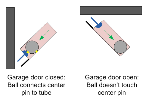
    A simple cadmium sulfide photoresistor cell detects the brightness of the garage, not only to determine if someone has left the light on, but also as a potential non-mechanical means of detecting a change in the door state. Primarily, the garage door position is detected by a tilt ball switch.

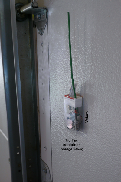
    Given that LoFi should cost less than $5, it only makes sense to use an equally expensive case. LoFi fits well in a Tic Tac box. The container is mounted to the garage door with Velcro hook and loop fasteners.

    I quickly discovered a problem with my steel garage door: it blocked the transmitter signal (L shaped house). The challenge was overcome by repositioning LoFi to the top of the garage door, such that the antenna stuck out above the top panel.

    All in all, this experiment is a success. LoFi correctly detects a change in garage door state, as well as delivers periodic updates on the door position, light level, temperature, and battery voltage.

  • Battery Life Expectancy

    David Cook06/29/2014 at 20:49 3 comments

    Power usage depends on the current of any sensors that you add, as well as how often you configure LoFi to check sensors and transmit. Transmitting consumes approximately 15 mA. Not transmitting, but constantly checking the sensors, consumes about 0.5 mA.

    A more likely scenario for battery operation is where LoFi transmits sensor data periodically or is activated by a trigger switch, say every 10 minutes. In that case, LoFi sleeps most of the time. As you will see, this allows for extremely long battery life.

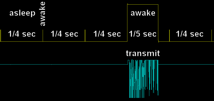
    This weekend, I coded and tested the sleep mode. LoFi uses the ATtiny watchdog to wake every 1/4 of a second to check whether it is time for a periodic transmission. It also examines the receive pin to see if someone is trying to configure the device. The digital trigger input (which can be connected to vibration or door switches) does not require polling. Instead, it will wake the device immediately.

    On the oscilloscope trace below, you can see LoFi wakes up briefly (narrow vertical spikes) before falling back to sleep. Each spike takes about 4.3 ms (oscillator start up + computations). Then, the transmit time occurs and LoFi takes about 200 ms to read the sensors and transmit the data.

    If a transmission occurred every 10 minutes, here is the average current draw:

    Only 18.5 microamps – thank you Atmel! Plug that into some common batteries:

    So, theoretically, you could run LoFi from a coin cell for a year. If you add a diode, capacitor, and small solar panel, then the life of the coin cell could be extended, as it would act as a backup at night. Realistically, with a pair of AA cells, you could forget about it for many, many years.

    Best of all, since LoFi includes the power supply voltage in the sensor data, you’ll know when it is time to change the batteries.

  • Testing Message Delivery

    David Cook06/26/2014 at 03:04 0 comments

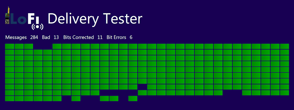
    Summary: Delivery Tester indicates LoFi works well through walls and across the house

    I built a simple test harness in C# .NET that visually displays the success or failure of receiving messages using LoFi on the 433 MHz band. The transmitter is running at 3 volts and is located approximately 75 feet away and down a floor. Each message is 21 bytes in length: 6 byte header, 8 byte message (five analog pins, a digital pin, voltage reference, and internal temperature), and 7 intermingled bytes of Hamming error correction.

    As you can see, most of the messages were delivered successfully (green squares). Those that aren't (blank spots) would be covered by retries or could be ignored if they are highly redundant status updates -- such as for water level or temperature monitoring. Hamming code fixed 11 bit errors. Six bit errors were not corrected and caused some of the bad messages.

    The bad messages generally occur in bursts, usually due to RF interference such as electrical noise or another 433 MHz device. However, as you'll see in the video, the errors towards the end are caused by operator rough handling. So, the actual delivery percentage is much higher.

    Live action video: http://youtu.be/lA8NtvYP6GI

  • Listening to Noise: Do aliens prefer hex 55?

    David Cook06/23/2014 at 22:06 0 comments

    When all of the transmitters are quiet, the receiver is listening to static on AM 433 MHz (see earlier log post). To avoid interpreting static as valid serial data, LoFi requires a message to start with 10 high bits followed by the letter ‘L’.

    Is there a more unlikely-to-randomly-occur value to start a message?

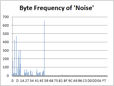
    I told LoFi to report all starting bytes 'acceptably' received from dead air for an hour. It produced 4224 samples or about one every second. There were quiet periods and noisy periods. Here is the frequency histogram:

    One byte per second is not bad, but it should be less often. Oh! There is a bug in the test program where it records additional bytes after the first.

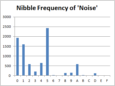
    Before I rerun the tests, let's take a closer look at the distinct values. The lack of bytes with the most-significant bit smells fishy. 0x55 (0b01010101) is the most popular value by far, either because:

    • The receiver is oscillating (probably)
    • Unrelated transmitters use that as a sync byte and LoFi is picking up that traffic (maybe)
    • Or aliens are trying to contact Hack-A-Day readers (plausible)

    Another possibility is electrical noise from nearby equipment. I disconnected LoFi from the Atmel STK500 programming board and sampled again for an hour.

    This time, only 36 errant bytes appeared in an hour. Excellent! They all are 0x55, so 'L' (0x4C) is a perfectly fine start for each message. Excellent!

    This leads me to two conclusions:

    • Always check your test code
    • Disconnect from potential sources of electrical noise, such as your programming board

View all 13 project logs

  • 1
    Step 1

    LoFi is expected to be delivered ready-to-use (prepopulated and preprogrammed). These instructions are for people that want to build LoFi themselves from scratch or are interested for curiosity. These instructions are expected to change as the project nears completion.

    Download and decompress the PCB layout files from this project page.

  • 2
  • 3
    Step 3

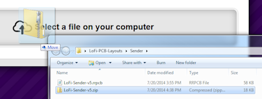
    Open the PCB layout folder and locate desired PCB you'd like to have made. For example, LoFi-PCB-Layouts/Sender/LoFi-Sender-v7.zip. Drag that zip file onto the OSH Park web page to upload it.

View all 16 instructions

Enjoy this project?

Share

Discussions

Bartosz wrote 01/30/2017 at 08:49 point

cc1101 texas instrument. more band , btter corecting data.

  Are you sure? yes | no

Shaun wrote 09/10/2016 at 19:22 point

Hiya David, would like to add value to project, maybe it can be ported to the Arduino world, and chance of getting access to the C code?

Fantastic work, great for IOT, keep it up, well done.

Best regards

  Are you sure? yes | no

bradsero7 wrote 05/16/2016 at 07:37 point

Could a microphone be added to this to make an audio surveillance piece, If so, how?

  Are you sure? yes | no

Luke wrote 08/04/2016 at 14:12 point

while audio recording is possible on a little chip like the attiny84a the 4kb of ram would make storage a bit of an issue :D

  Are you sure? yes | no

cuyler wilkinson wrote 05/10/2016 at 23:30 point

in 1983 i had a tandy color computer 3 which i built a "clapper" switch to control the LR lights with. i ran wires and a 9 volt relay from my cassette powered tape drive "port". i think it was a-dos machine language? still binary just as lotus,windows,linux,ubuntu,apple and ardweenie-o pi.  here's the source code: goto, back,next,plus,then, l & O.

  Are you sure? yes | no

voy.ager wrote 04/27/2016 at 08:41 point

Wow ! What a lot of work for just faking around. Project looks good but i believe this never worked and never had a chance. If it really worked, there should be no problem publishing the working Source codes if it is declared as Open Source. There are lot of mysteries in the Net.

  Are you sure? yes | no

Jorge Fabre wrote 04/14/2016 at 04:02 point

I just came across this project. I am really interested but reading the comments below I'm hesitant to continue as the source code is no where to be found. David would you kindly help us with this. 

Thanks for your great work. 

  Are you sure? yes | no

Dylantje wrote 02/27/2016 at 17:26 point

Dear...

Is this project still alive??? [ looks great/simple..

Is there a simple how to for a dombo like me?

  Are you sure? yes | no

John Chiasson wrote 01/14/2016 at 15:23 point

I'm interested for home automation as well.  Anyone know if the boards are available, or if there is any source that will build them inexpensively?

  Are you sure? yes | no

Nits wrote 01/11/2016 at 05:32 point

by when this is available?

  Are you sure? yes | no

Indigaz wrote 07/03/2015 at 03:33 point

I too would like to add to the chorus of those interested in this project and would greatly appreciate the opportunity to use the source code as a learning tool.  I'm doing my best to learn microcontroller programming and seeing how someone achieves a task is the best way for my brain.  When I first saw this project during the first HaD prize and after seeing these things(transmitter/receivers) all over eBay for cheap, I was elated.  

  Are you sure? yes | no

alon24 wrote 06/28/2015 at 08:50 point

Hi, can you share the code? 

This might be ported to Just an esp8266.

  Are you sure? yes | no

Avamander wrote 07/17/2015 at 11:48 point

Try NRF24L01+ instead. Also, this project has been abandoned, it is kinda sucky that as soon as the person found out that he did not win, he abandoned the project. 

  Are you sure? yes | no

Edoardo wrote 06/03/2015 at 18:38 point

Hi,

This is seriously awesome, well done!!

But, as the others, I too would like to see the sourcode! Could you please put it in a repository or link us there?

Regards

  Are you sure? yes | no

tomg09 wrote 05/23/2015 at 19:38 point

I understand this project is shut down...but would you be willing to post the code you have somewhere?  Anywhere?  You don't have to maintain it, just post it so others can continue your work.

  Are you sure? yes | no

Ken Burgess wrote 04/15/2015 at 06:34 point

This project is too cool for school, this should be a product/tool for the Arduino enabled.

Is there a plan to supply finished modules? I do SLS production 3D printing, would volunteer to do some packaging...

  Are you sure? yes | no

Roger Guess wrote 04/03/2015 at 15:26 point

David, I just found this project. Amazing. If you have a desire to continue. I believe quite a few of us would support you.

  Are you sure? yes | no

Mohamed Nuwaos wrote 01/26/2015 at 03:13 point

this seems to be very cool gadgets,thanks for sharing, pls let me know where to buy the circuit board,or the transmitter. nuwais64@gmail.com.....the only Sri lankan following you haha

  Are you sure? yes | no

mikko.pihlajamaki wrote 01/05/2015 at 08:47 point

It would seem that this project is killed and buried.

  Are you sure? yes | no

Elliot Williams wrote 11/01/2014 at 21:20 point
Seriously great implementation and documentation, Dave. You shoulda won, IMO.

(Fan of the Robot Room from waaaaay back, FWIW. Thanks.)

  Are you sure? yes | no

mikko.pihlajamaki wrote 10/28/2014 at 08:30 point
David,

Is there any hope that you might continue with the project? It shows so much potential.

  Are you sure? yes | no

wifiwaves wrote 10/22/2014 at 23:35 point
David,

Check your email...

Thanks...!

  Are you sure? yes | no

Similar Projects

Does this project spark your interest?

Become a member to follow this project and never miss any updates