 David Cook
SENDER
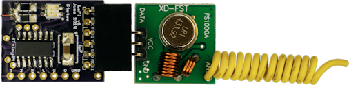
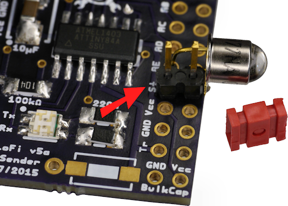
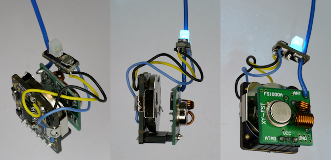
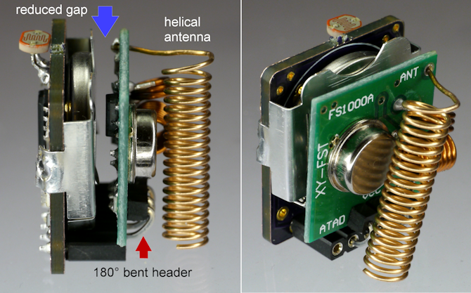
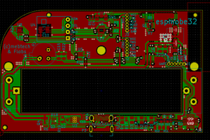
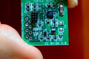
The sender is compact (1.25 sq. inch) and operates from 1.8 to 5.5 V. The module consists primarily of an Atmel ATtiny84A which monitors the inputs and outputs the data. A red and green LED provides visual status.
The sender module has:
- Five analog inputs with configurable triggers
- Digital trigger
- Built-in temperature sensor
- Battery voltage measurement
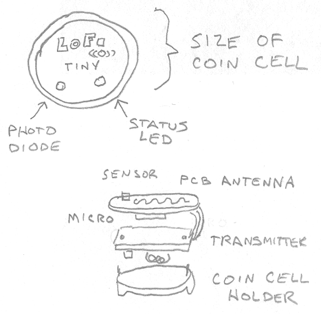
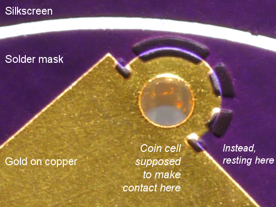
- Optional CR2032 coin cell holder
- Optional pushbutton to manually activate data transmission
CONFIGURATION
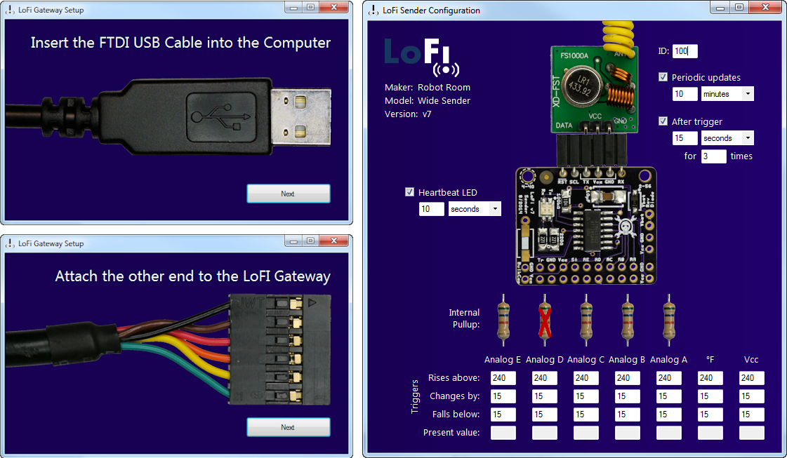
Without any programming knowledge, the sender module can be configured to transmit:
- On power up
- When any analog input goes above a certain value
- When any analog input goes below a certain value
- When any analog input changes by more than a certain amount
- Periodically from 1 second to 18 hours
Configuration is accomplished using a laptop or desktop connected via a standard FTDI serial cable.
LOW COST
The sender costs only $2.43 in parts (qty 1000) or $3.50 (qty 10). Think of all the things you can monitor at that price -- in the garage, basement, garden, kitchen, or bedroom.
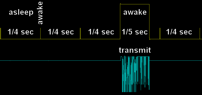
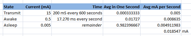
LOW POWER
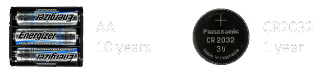
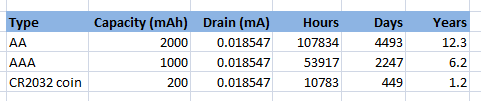
The sender uses only 18 µA on average. This means it can be installed in small places while running on a coin cell, or can be virtually maintenance free with a pack of AAs.
CONNECTEDNESS
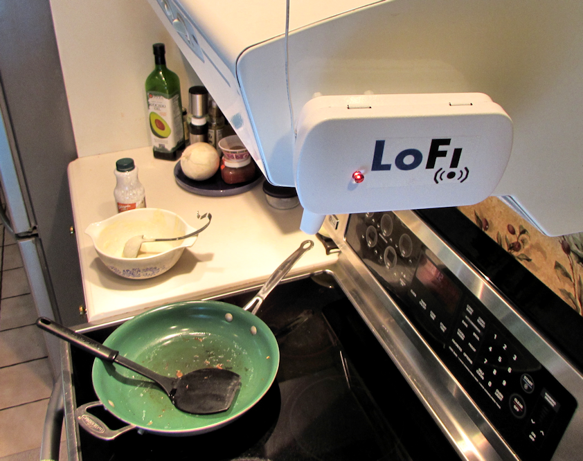
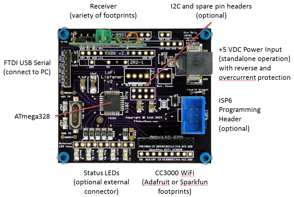
The LoFi gateway listens to all of the senders and uploads the data to a PC or to the Internet. LoFi is compatible with data.sparkfun.com (aka Phant), a free open-source Internet repository. As demonstrated in the Semifinals video, you can connect LoFi to the Internet in under 2 minutes.

INTERFACE
The interface couldn't be more easy. On the sender, simply solder sensors to the standard 0.1-inch pitch holes. No programming necessary. On the PC, the software walks you through each connection step and lets you modify device configuration in a friendly UI.
Non-proprietary output means you can use all of the repository tools written for Phant (or for the JSON, XML, tab values it provides). The output from the Gateway to the PC is tab-delimited plain text, so you can log it in a terminal program or write your own software regardless of OS.
LEARN MORE
Battery Life Expectancy (1 year on coin cell, 10 years on AA)
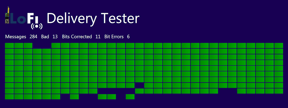
Message Delivery Rate (>95% success rate)
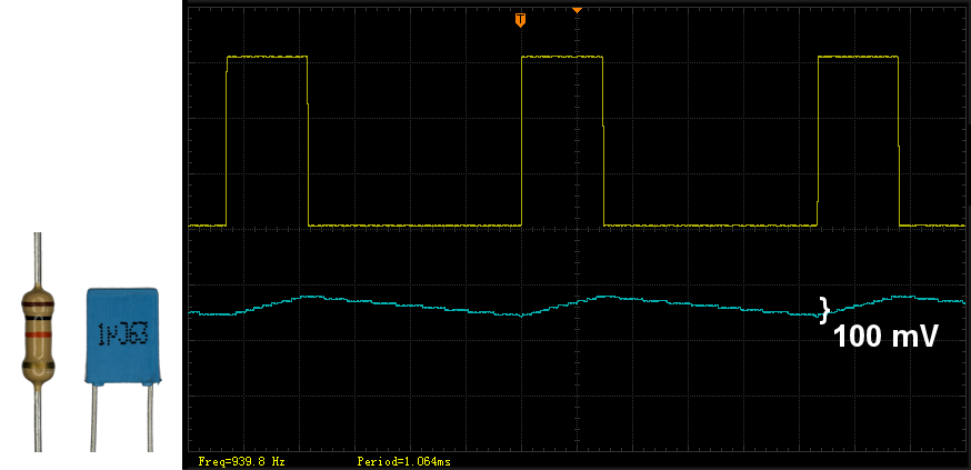
Dealing with Static: Auto Gain Preamble and Error Correction
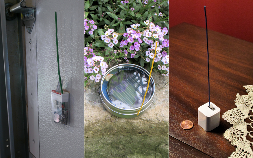
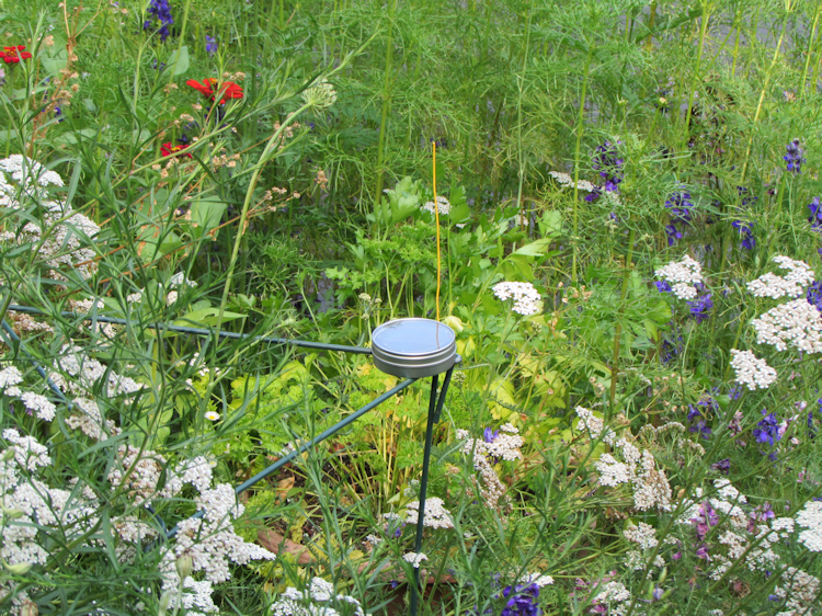
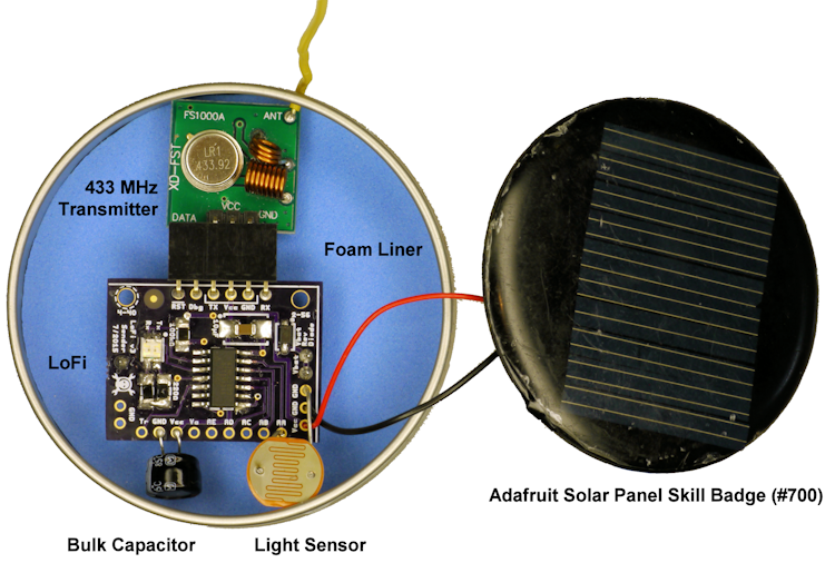
LoFi as a Solar-Powered Weather Station (temperature and light levels)
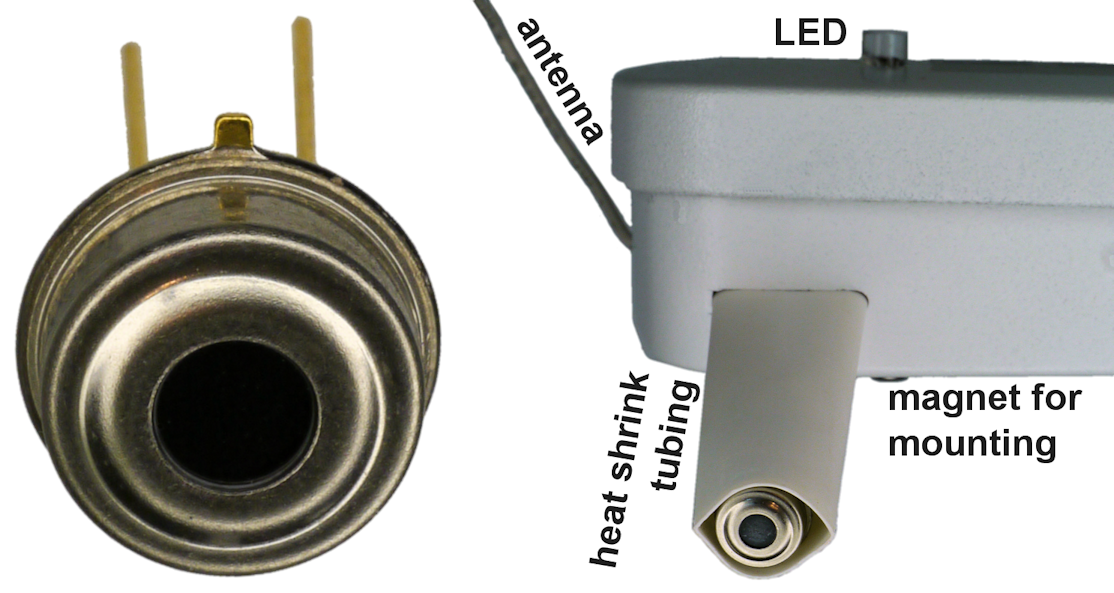
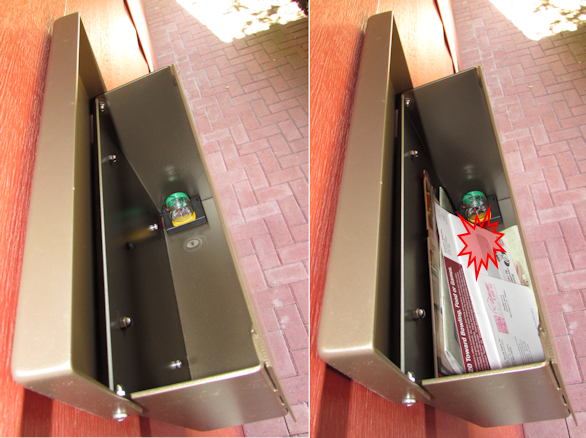
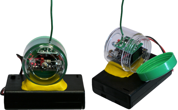
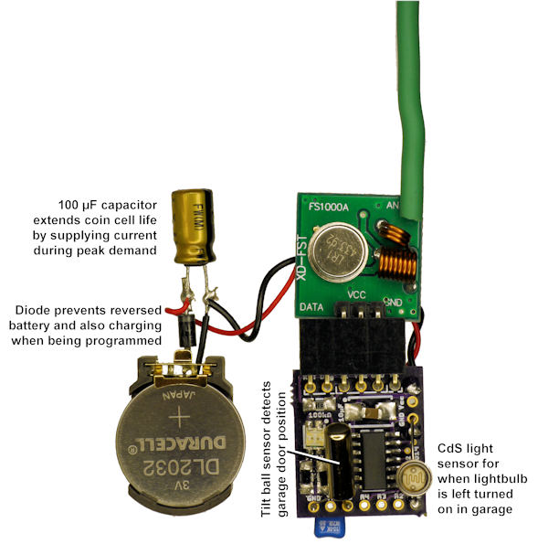
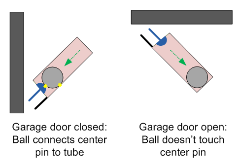
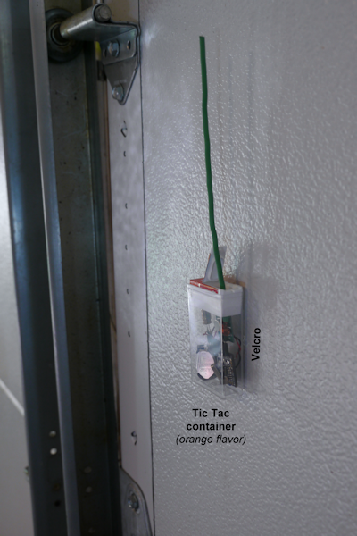
LoFi Detecting Garage Door State (tilt ball switch)
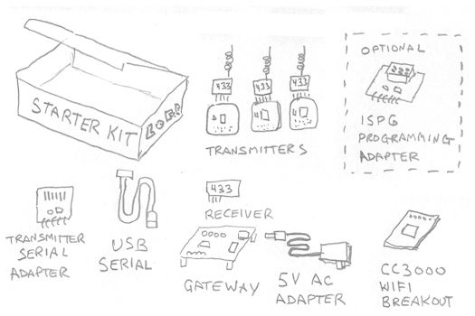
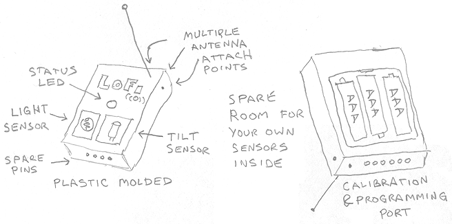
Artist Rendition of Productized Look and Feel (contest requirement)
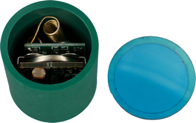
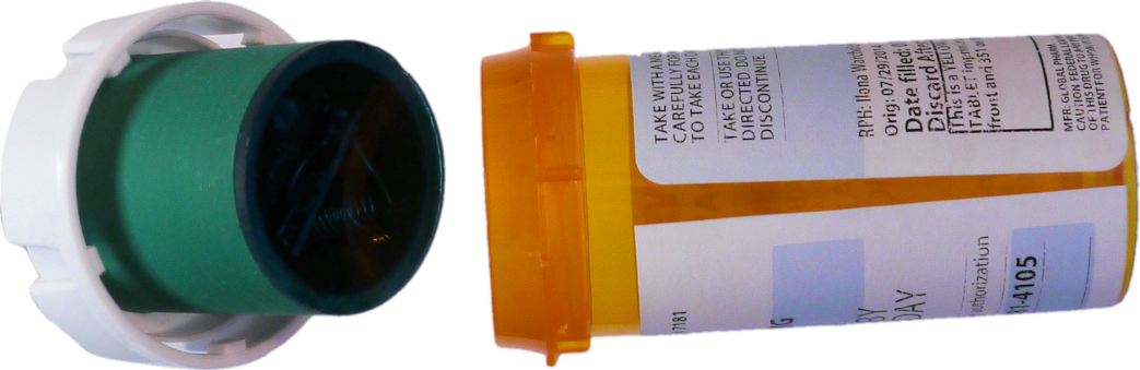
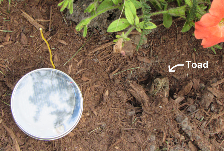
Good Things Come in Small Packages (fitting into a pill bottle and iPhone charger)


 Samuel Wantman
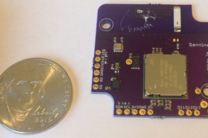
 Kris Winer
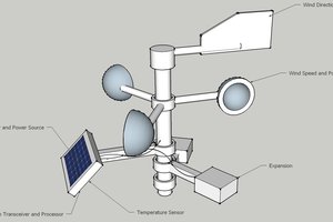
 Ulf Winberg
Thanks for the inspiration! I linked your project in my hackaday.