0%
0%
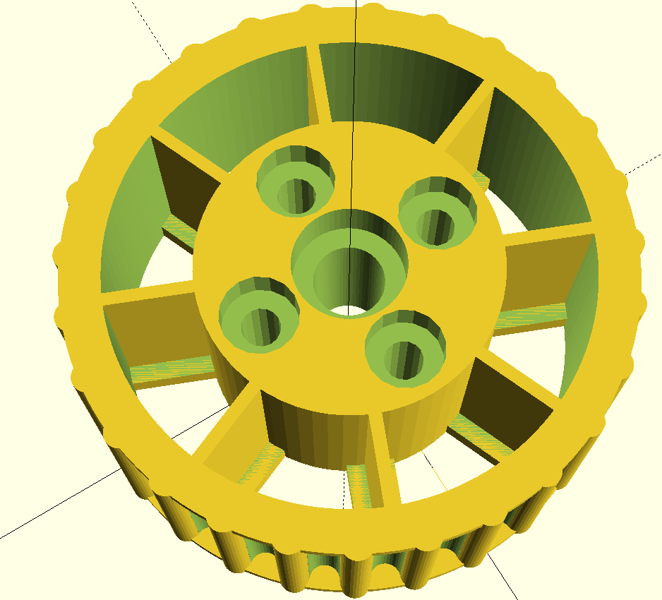
OpenWheel : parametric OSH wheels/tyres/tracks
Openwheel provides parametric open source wheels, tyres and tank tracks completely 3D printable, with lots of options, for robots and more
 Audrey Robinel
Become a Hackaday.io member
Already have an account? Log in.
Just one more thing
To make the experience fit your profile, pick a username and tell us what interests you.
Pick an awesome username
hackaday.io/
Your profile's URL: hackaday.io/username. Max 25 alphanumeric characters.
Pick a few interests
Projects that share your interests
People that share your interests
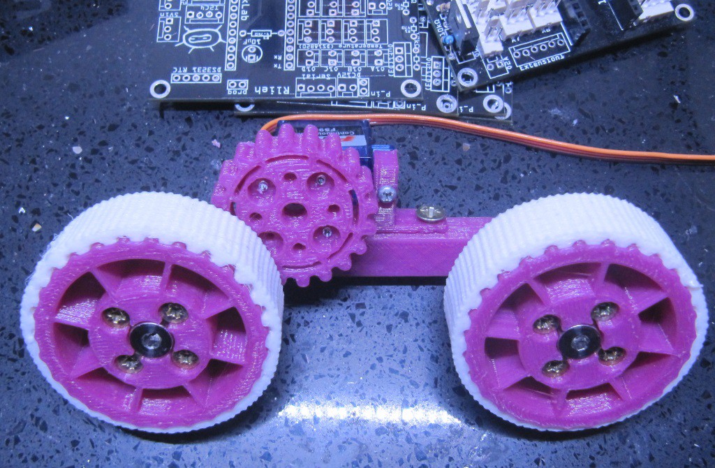
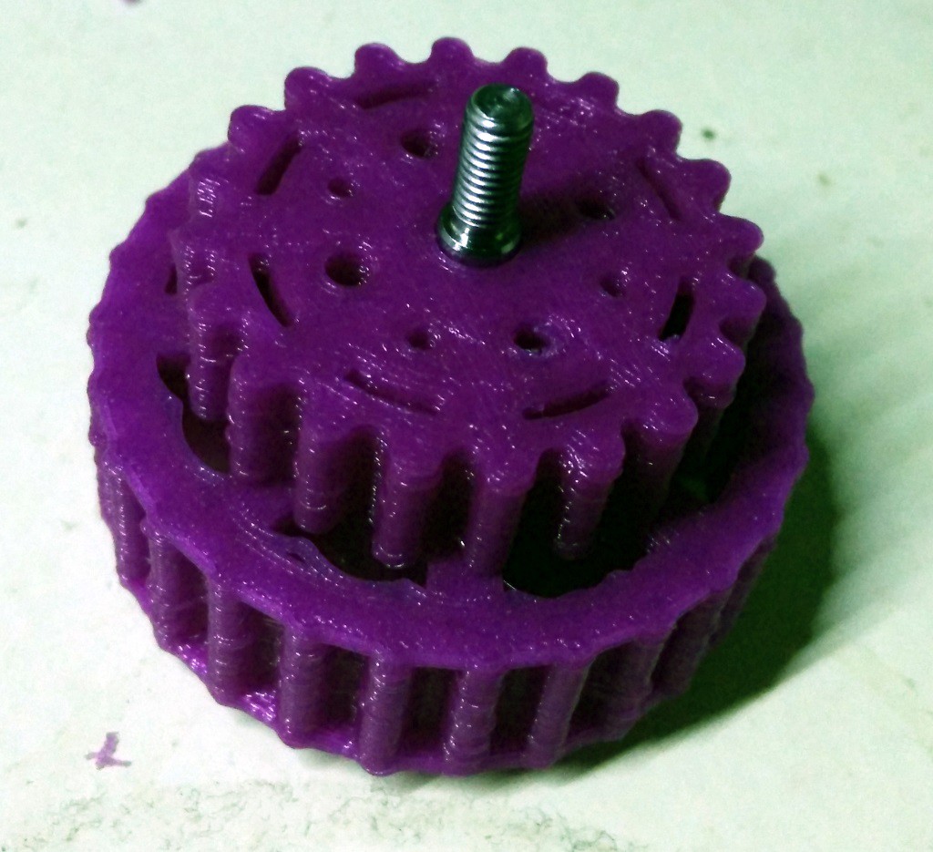


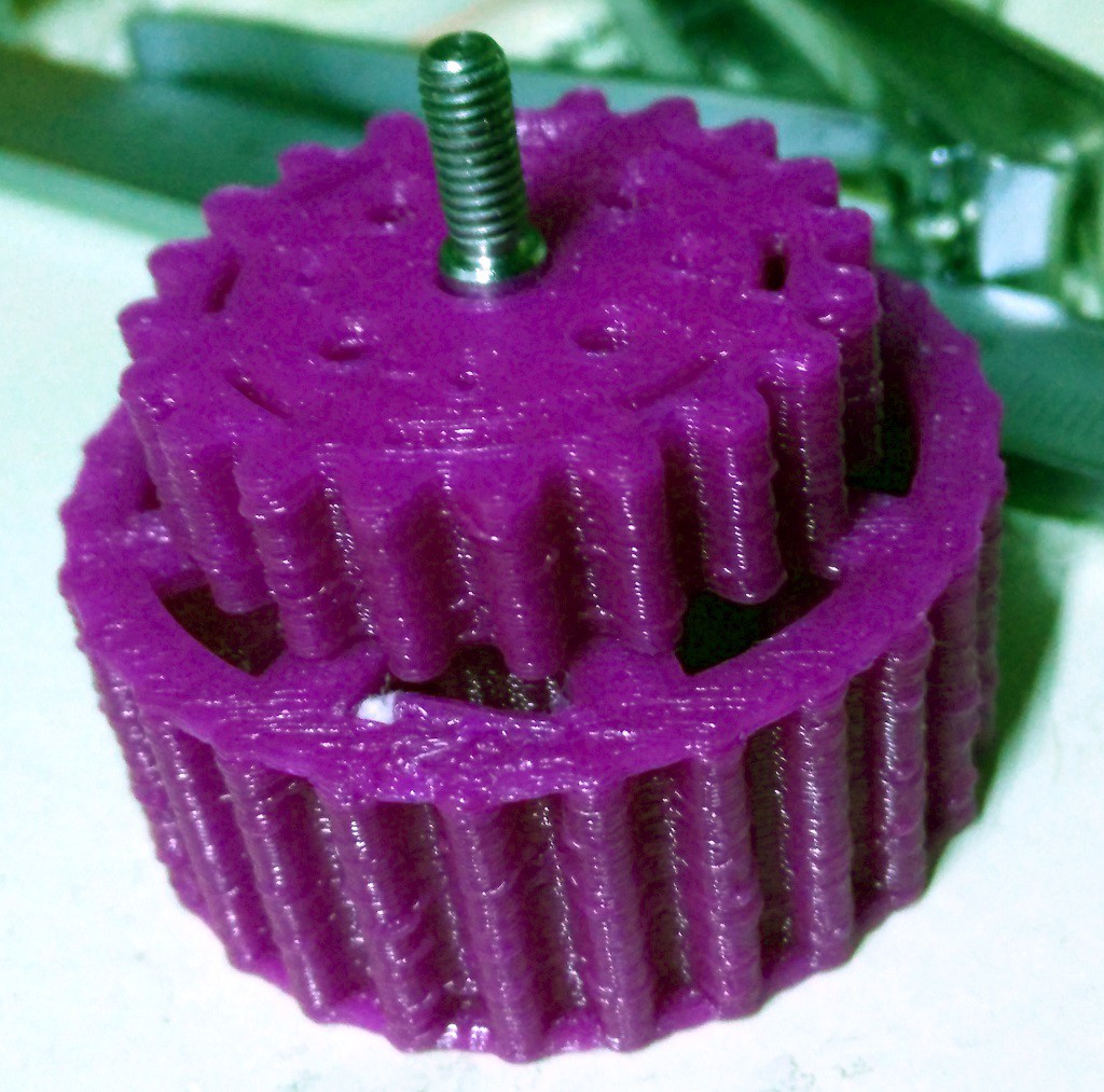 On the picture above, you can see a 22 cogs gearing on a 27 cogs wheel, using the same axle. On the picture below, you can see how it is secured with 4 screws. Note that all screws are countersunk, and thus the side of the wheel has nothing sticking out to block the robot on an obstacle.
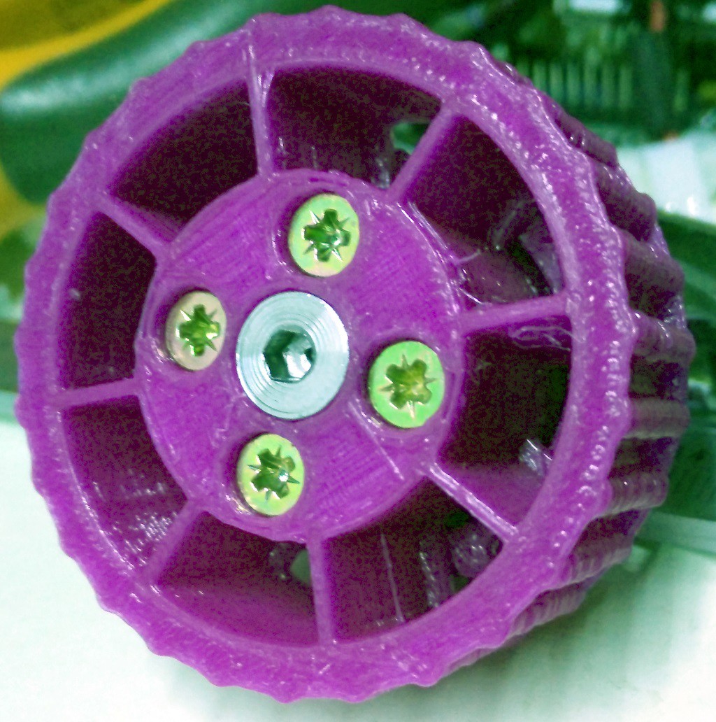


 Tim Wilkinson

 Gertlex
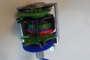
Hey that looks pretty cool! Nice work so far.