0%
0%
3D Printed Robot Joint with Active Compliance
A general purpose robot joint using a cycloidal gearbox and an ODrive modified to support active compliance
 Tim Wilkinson
Become a Hackaday.io member
Already have an account? Log in.
Just one more thing
To make the experience fit your profile, pick a username and tell us what interests you.
Pick an awesome username
hackaday.io/
Your profile's URL: hackaday.io/username. Max 25 alphanumeric characters.
Pick a few interests
Projects that share your interests
People that share your interests
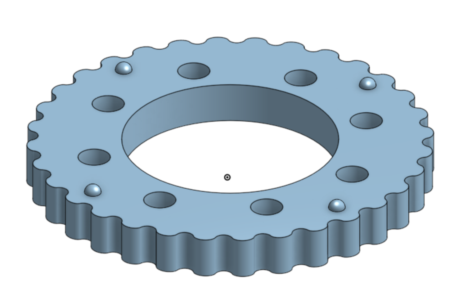
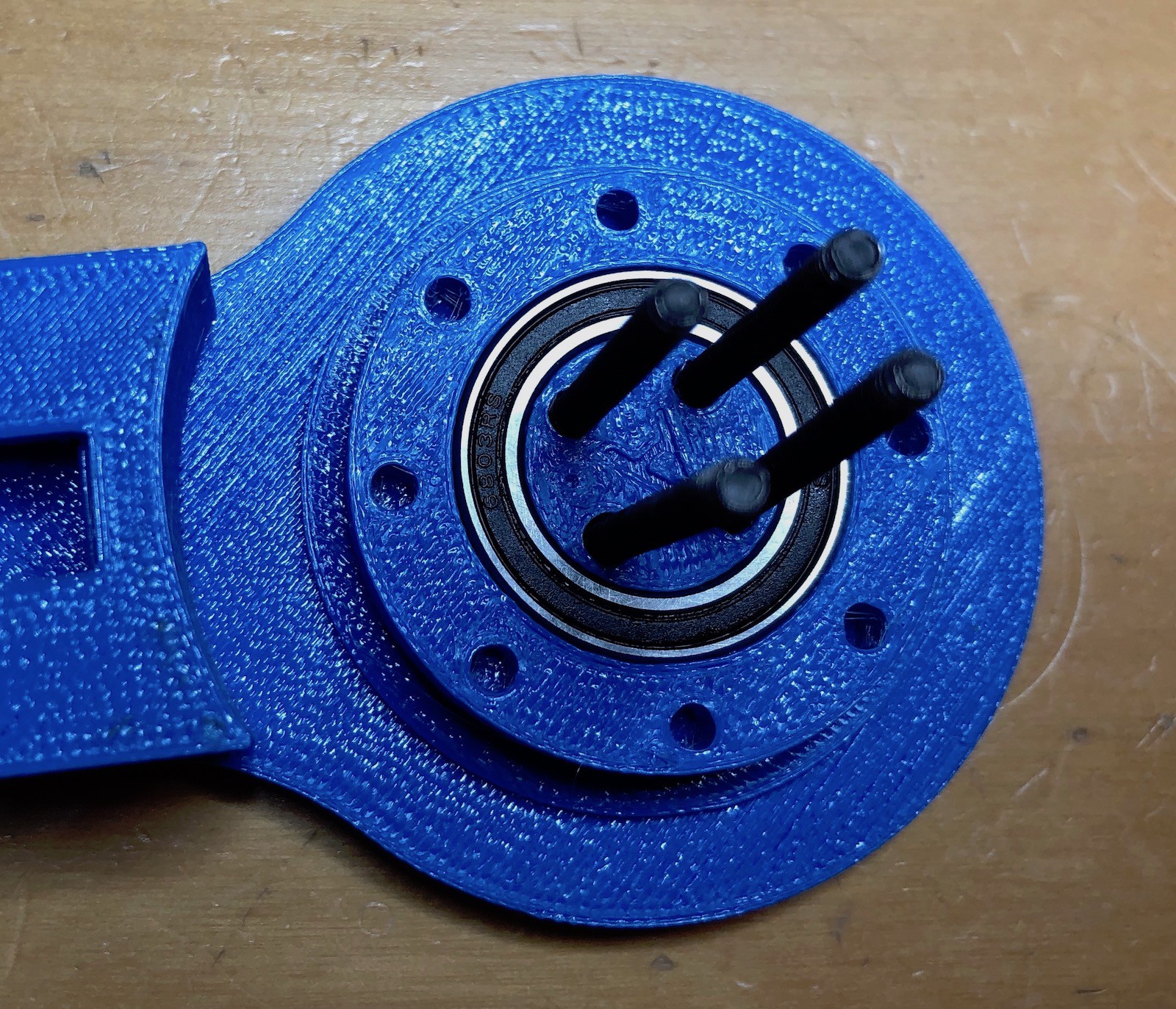
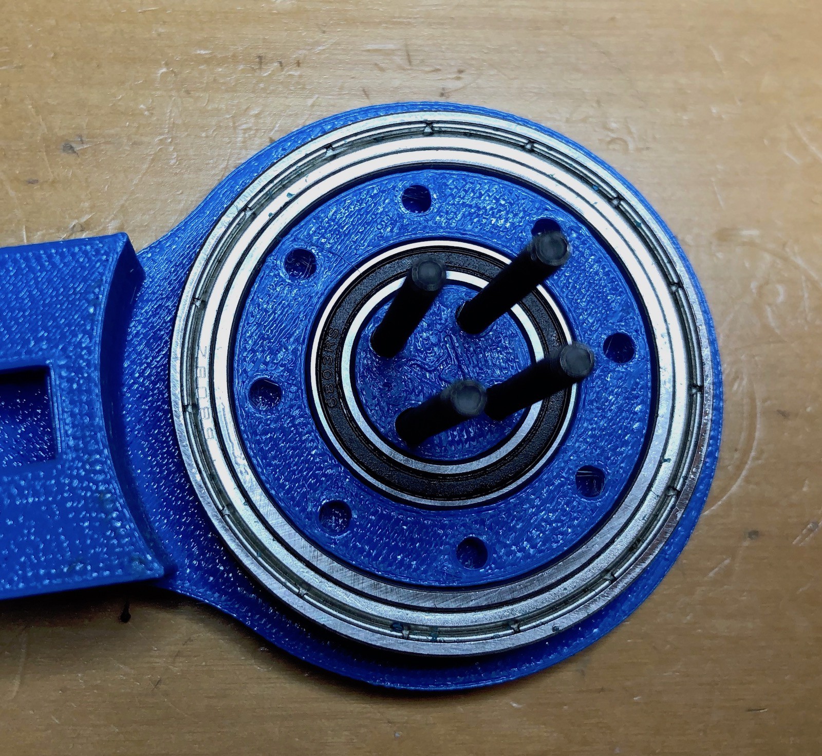
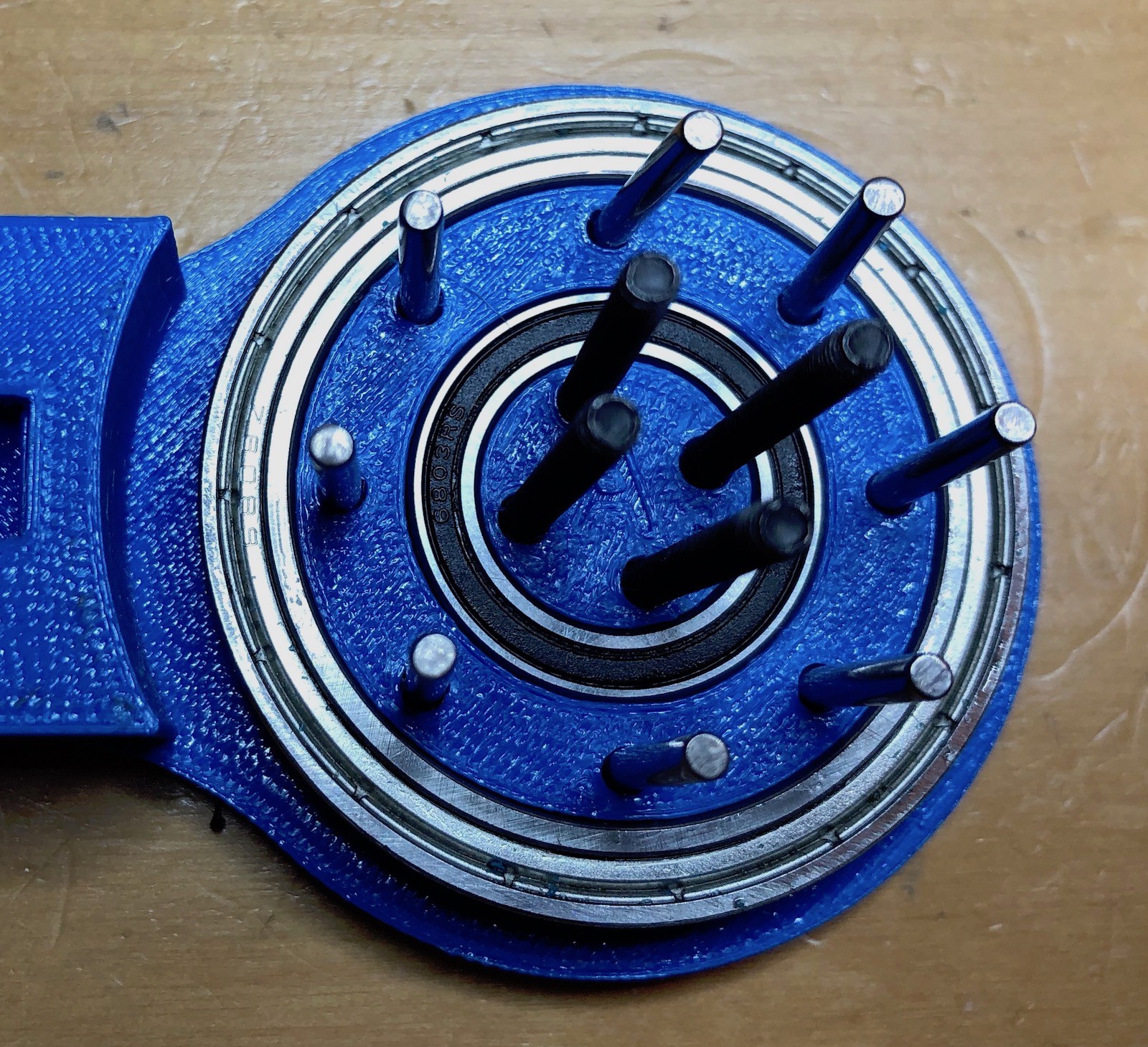
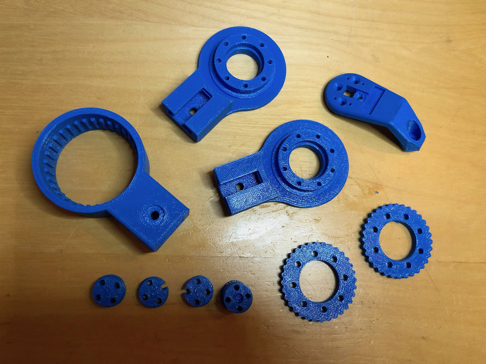
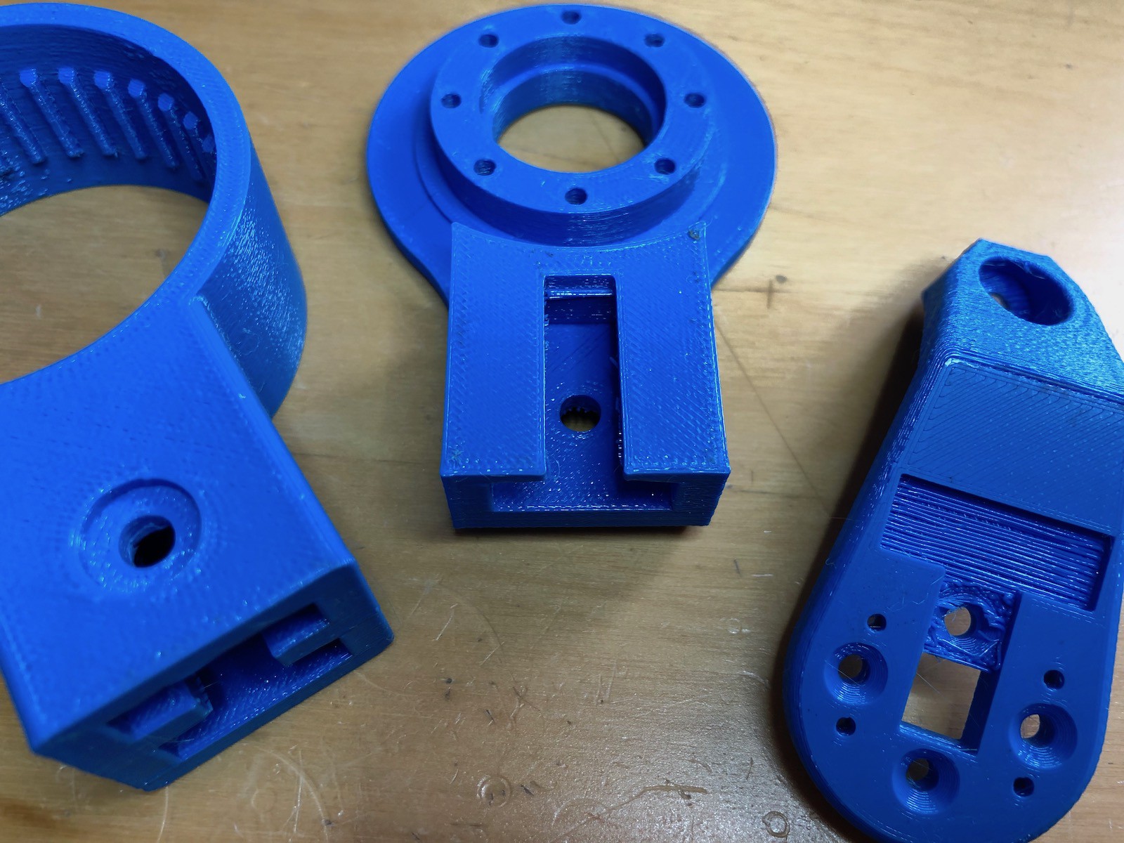
 I don't begin to understand where the load and stresses on this design are, but clearly there's quite a bit on the pins, and while they're made of metal, the cycloidal disks are just plastic. So this part needs to be reprinted with more infill and an increased number of perimeters. I originally just used 20% infill and 2 perimeters, so I'm going to up that to 50% and 6 and see how they new disks survive.
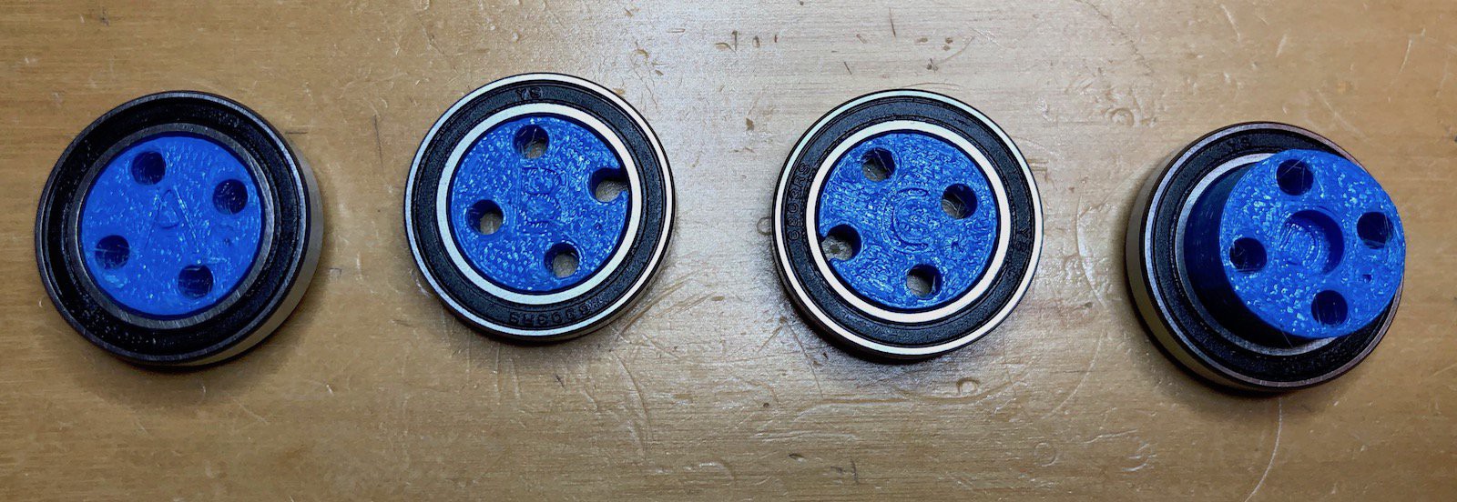

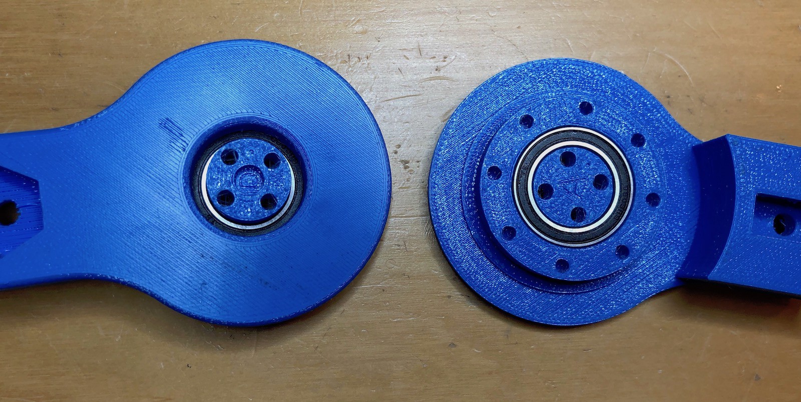
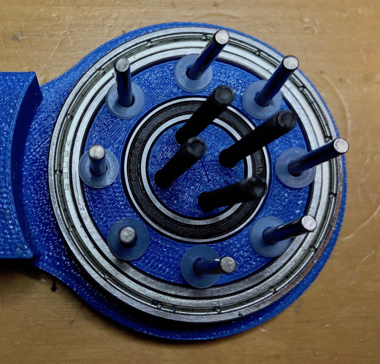

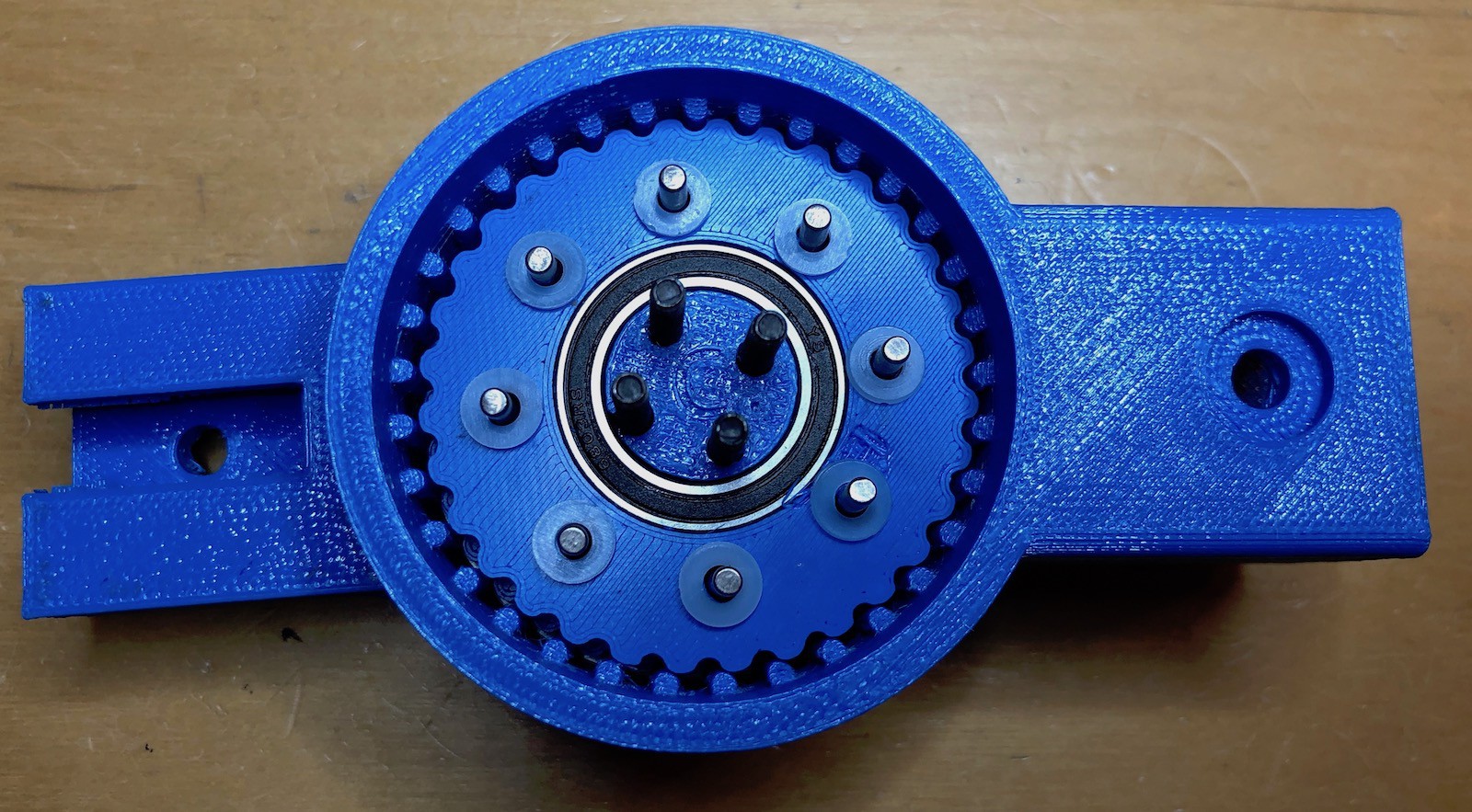
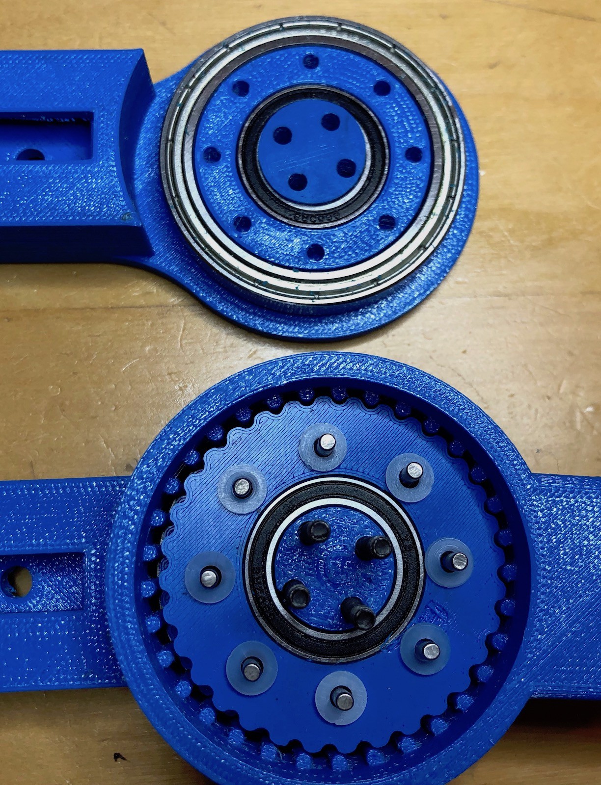
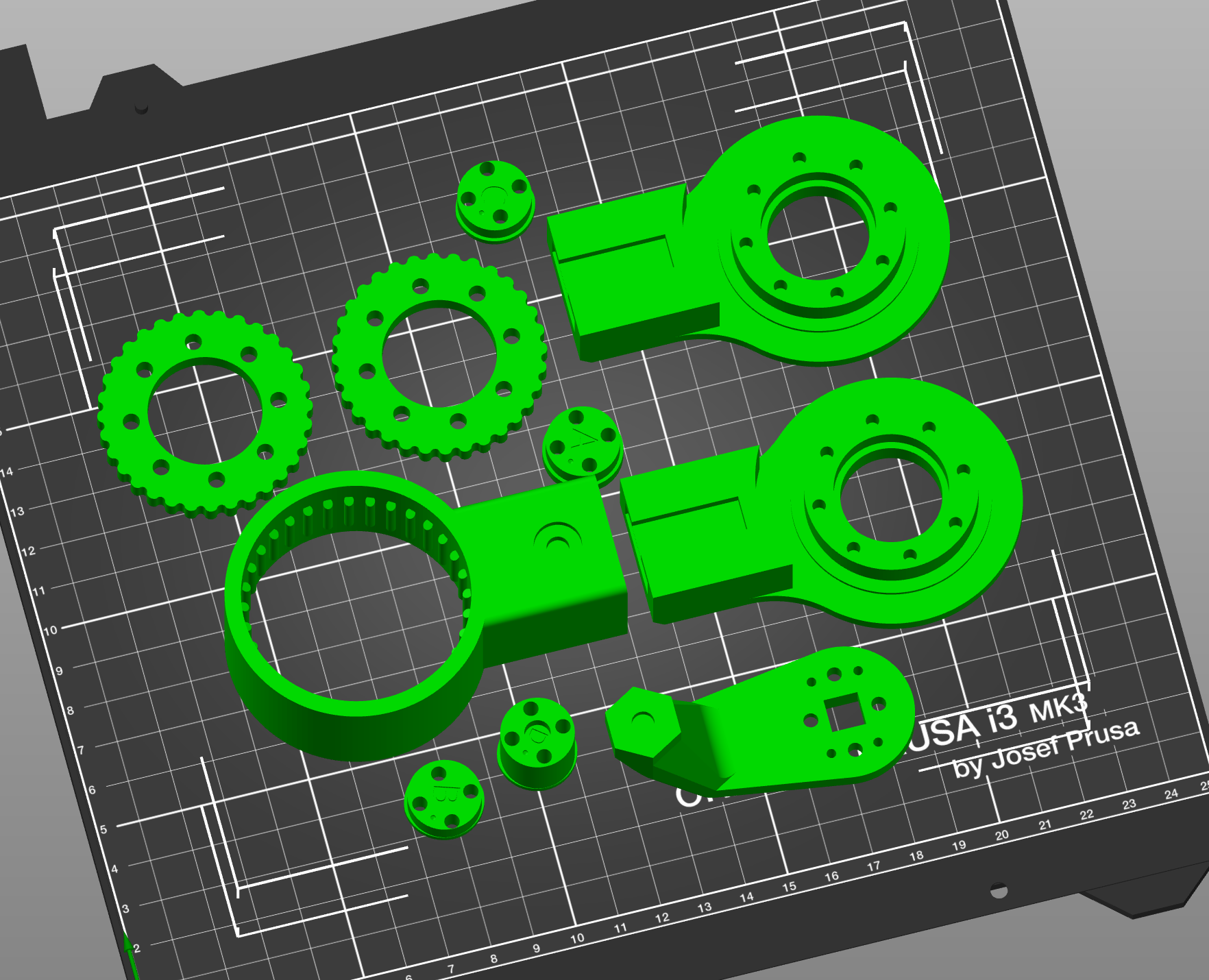
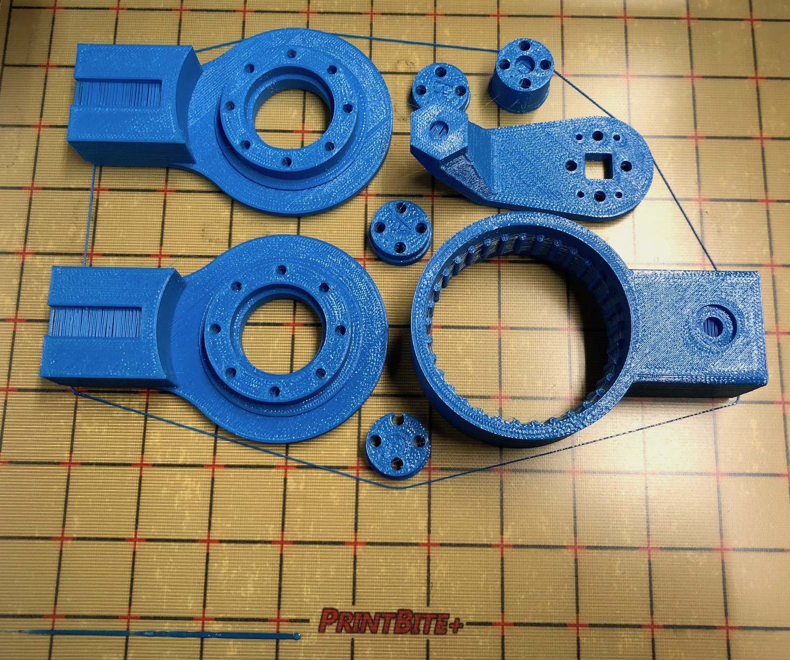 The above photo shows the printer parts just before removing them from the printer (although it's worth noting I forgot to print the cycloidal gears so had to do those separately). Note that I'm not using the standard print surface from Prusa as this PETG stuck aggressively to it. Instead, rather than use Windex or blue painters tape as an interface layer, I'm using the


 Michael G
 CLo
CLo
 jellmeister
 Charles Galambos
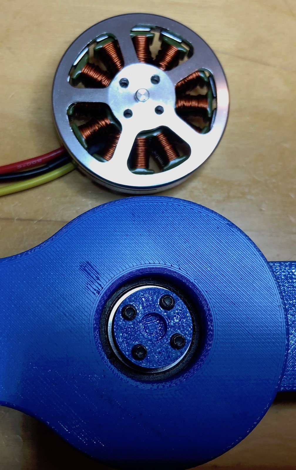
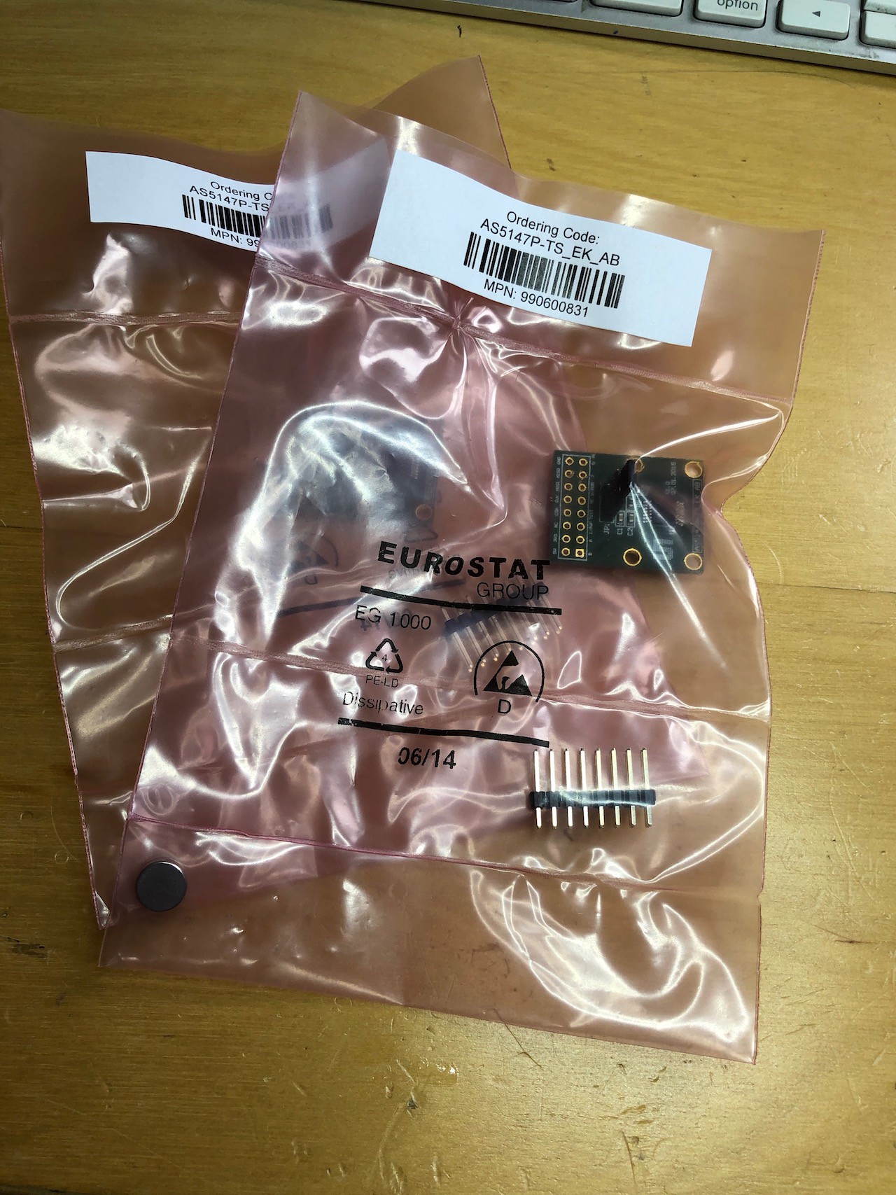
Hey, thanks for sharing, you saved me a hours designing a AS5047-5010 motor mount!