INTRODUCTION
An ALU (Arithmetic Logic Unit) is an electronic circuit that performs arithmetic and bitwise operations on binary numbers (see Wikipedia: ALU).
This project describes three different ALU's that work with relays.
After simplyfing one of the Relay ALU designs of Dieter Mueller (see HERE), I experimented with a design that has both input signals (A and B) connected to a single relay coil, so the relay will be active when both inputs have a different logic level.
This has been done before, but for an ADD function only (like the 1-bit Relay Full-Adder described by John Stanley).
When I entered this project here at Hackaday, this ALU design had 5 functions. I described the operation of the circuit comprehensively in two logs.
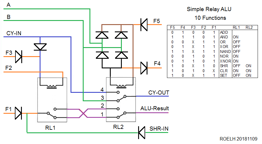
Now that I changed the design to have 10 functions, I don't want to change all those descriptions. So the 5-function design is first explained below and in the first two logs. The third log ( found HERE ) explains the new 10-function design.
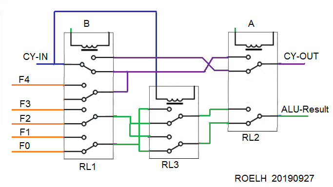
The fourth log describes another relay-based ALU design, this time without diodes.
FIRST DESIGN
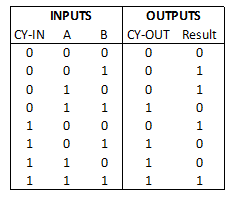
The ALU can ADD, and can perform the basic logic operations. The operation is selected by the four inputs F0-F3 (that are in common for every bit):
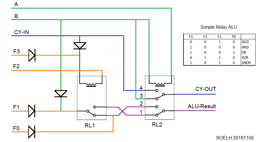
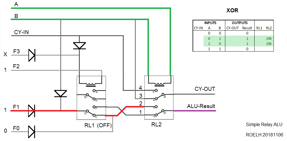
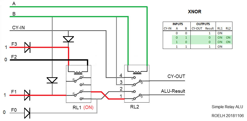
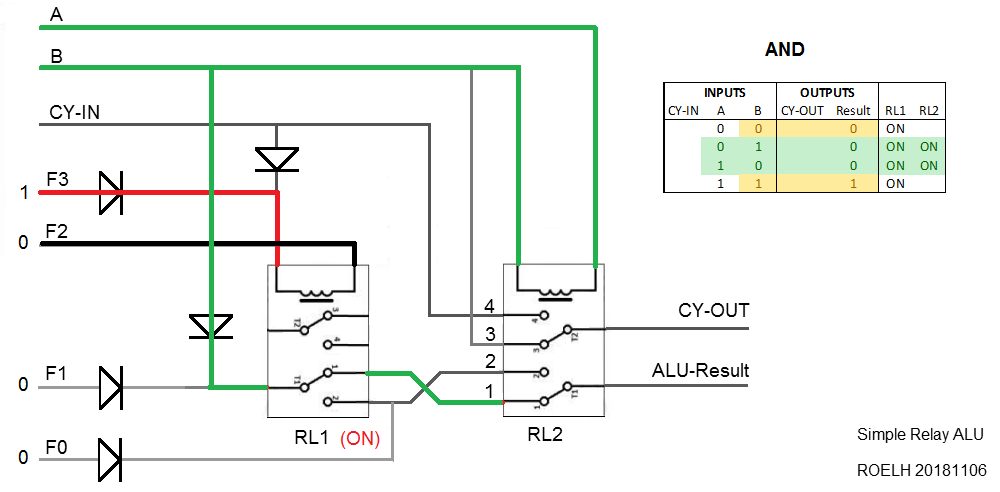
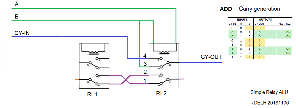
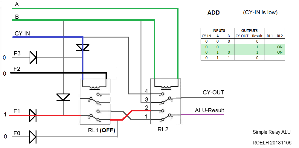
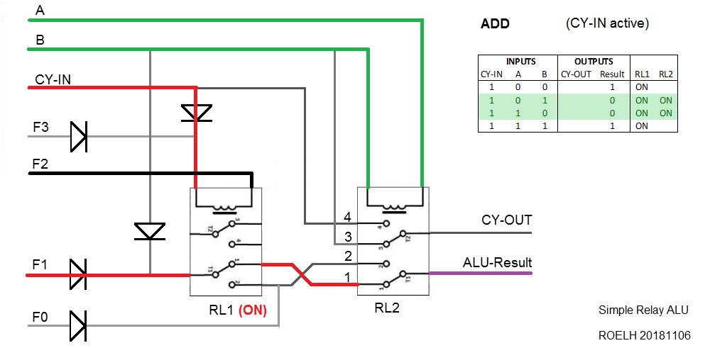
The picture shows a single bit of the ALU. Several of these circuits can be chained together to form an ALU that operates on 4 or 8 bits (or any other number of bits).
GREEN wires show the A and B input signals.
DARK BLUE wires show the carry path.
ORANGE wires show the control inputs.
Please be aware that:
- Relay RL1 needs a flyback protection diode, see Flyback diode.
- Relay RL2 be must not be sensitive to the signal polarity. If the relay is polarity dependent, you could use a bridge rectifier (see picture below). The bridge will also act as flyback protection diode.
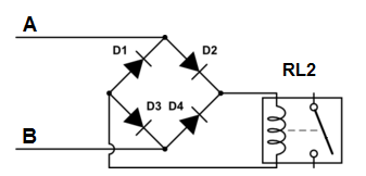
- If you do not use a bridge rectifier for RL2, you can not use a simple flyback diode because both polarities can be present. Easiest solution would be to mount a resistor in parallel to the coil, with the same resistance as the relay coil. This will limit the generated reverse voltage (but will also increase power consumption when the relay is ON).
- Using DC, 12 Volt is recommended.
- The inputs to the circuit must be 12 volts for a "1" (but F2 may be left floating for a "1")
- The inputs A, B and F2 must be connected to ground for a "0". The other inputs may be left floating for "0".
- In the function table, "X" means that the input may be either 0 or 1.
CARRY DELAY
The design has practically zero carry ripple delay, so the addition speed is independent from the bit-width of the numbers that are added. It shares this property with the famous Zuse Adder, described at this page of the Hamburg university and in this Relay-Computer-Two article.
OPERATION
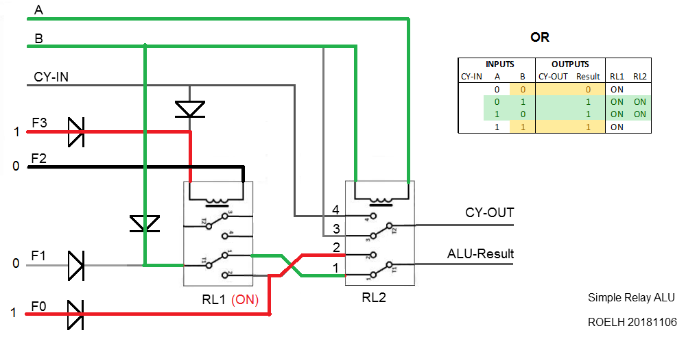
The operation of the circuit will be discussed in detail in the logs. The first log will describe the ADD function, and the second one wil describe the logic functions.
SIMULATION
The design was successfully simulated in the Falstad simulator. In the Falstad File menu, select "Import from text" and paste the contents of the simulation file (available in the files section), to do the simulation yourself. The simulator shows the current that flows through the wires, and you can see the relay contacts switch !



 Tim
Tim
 Yann Guidon / YGDES
Ciao Roelh! Your ALU designs are really genius!!
I'm preparing myself to build a relay computer, and I was wondering if you could have some nice alternative that might use 4PDTs (I've bought ALL of this type since price for the type I bought was almost the same and to minimize their quantity in general where possible). If possible would be nice also at least one of the two inputs +12V/disconnected instead of +12V/0V (this in order not to add 8 more relays since one of the values is coming from a punched card reader that would make contact or not, while the other is coming from a register).... The basic functions I'm interested ar "just" ADD, AND, SHR (for the rest I think I can manage with very limited calculations).