Close
0%
0%

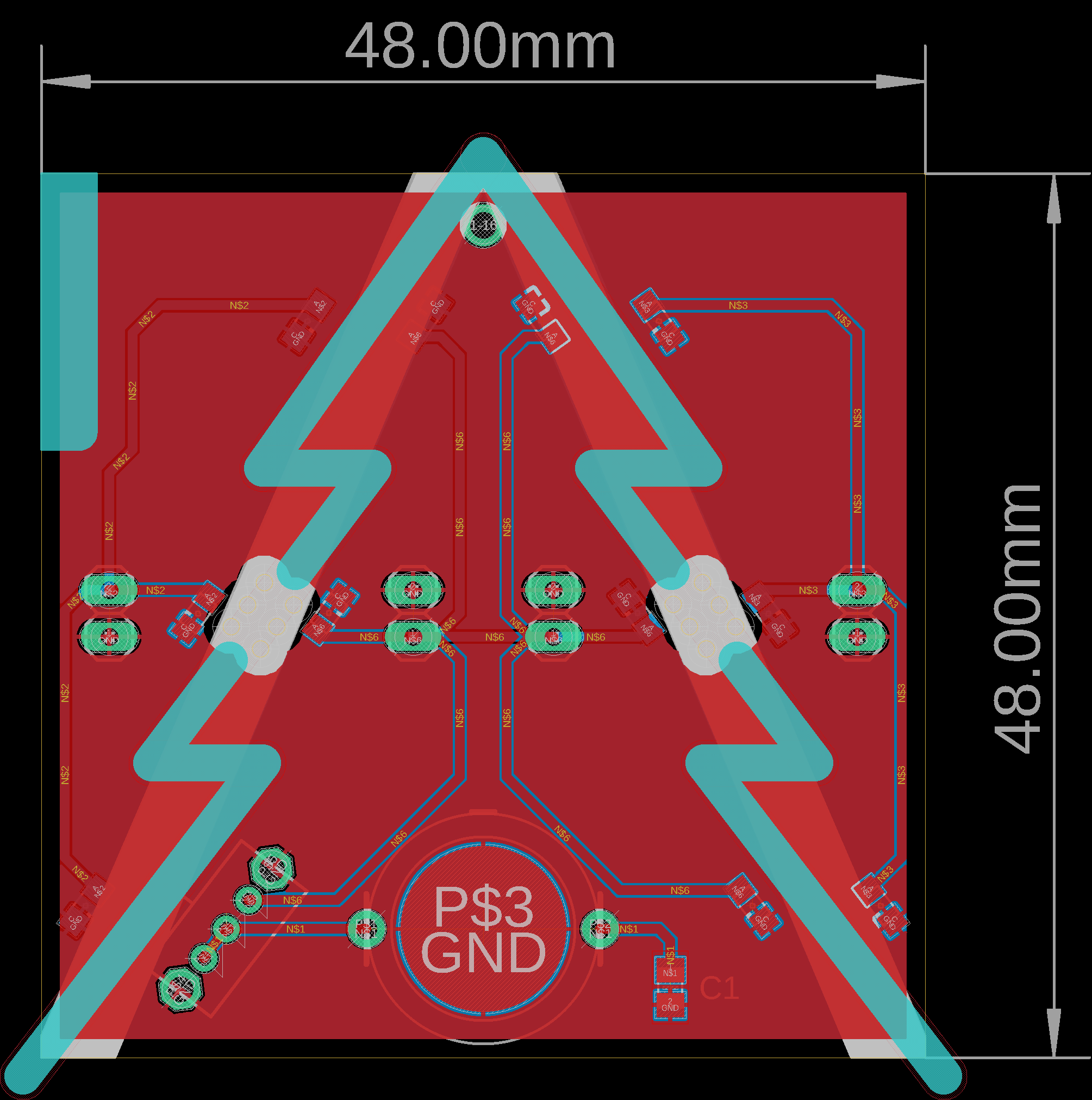
$1 PCB Christmas Tree

A Christmas tree made on printed circuit board with embedded 0805 SMD flashing LEDs

Similar projects worth following
PCB Christmas tree
by Loann BOUDIN | 2018

When Christmas is coming, what can an electronics lover do ? A PCB Christmas tree of course !

As a member of a small electronics hobbyists club, I like to share my passion for electronics and PCB design through small projects. For Christmas, I wanted to introduce SMD soldering universe to new members with a fun and simple project: solder a miniature PCB Christmas tree with embedded 0805 SMD flashing leds.

This tutorial describes the process I followed to imagine, design and create a bunch of cheap, small, glowing Christmas trees on printed circuit boards for less than $1 the unit. Enjoy :)

RAR Archive - 49.19 kB - 01/03/2019 at 13:46

Download

View all 6 components

View project log

  • 1
    BOM, Tools and Skills Needed

    You will need:

    Necessary tools:

    • soldering iron
    • solder wire
    • sandpaper
    • flat pliers
    • cutting pliers
    • fine tweezers

    Optional (but handy) tools:

    • Fume extractor
    • multi-meter
    • magnificent glass

    Skills:

    • basic soldering skills

    Bill of materials:

    Components Supplier Wholesale price ($) Price per PCB ($)
    11x 0805 SMD blinking leds Aliexpress 15,79 0,29
    1x CR1220 battery

    Aliexpress

    0,75 0,15
    1x battery holder

    Aliexpress

    6,58 0,07
    1x toggle switch

    Aliexpress

    2,62 0,03
    2x 2 pins header

    Aliexpress

    0,51 0,01
    1x PCB

    SeeedStudio

    4,90 0,12

    I've chosen cheap components to keep the BOM below the symbolic price of $1 per Christmas tree PCB. The total price for one PCB Christmas tree with all the electronic components soldered is estimated to $0,67.

  • 2
    PCB Design

    I designed my PCB Christmas tree using Autodesk EAGLE. EAGLE is an electronic design automation (EDA) software enabling schematic diagrams design, component placement and PCB routing.

    I started the design by creating the schematic of the electronic circuit. It consists in 11 flashing LEDs in parallel, powered by a 3 V button cell battery. A switch can open or close the circuit. Finally, an optional filtering capacitor of 10 µF is placed between the battery voltage and the ground.

    I made the choice to not include a resistor in series with the LEDs as 3 V is very close to the forward voltage of many LEDs colors:

    LEDs colors

    The schematic and the PCB are divided in three parts:

    • the main board: it has a Christmas tree shape and includes the battery holder, the switch, 3 LEDs on the top face and 2 LEDs on the bottom face. Two 2-pins pinhead connectors allow to connect and power the two fins, one on the top face and the other on the bottom face.
    • the top fin: it has a shape of half a Christmas tree with a notch for the battery holder and includes 1 LED on the top face and 2 LEDs on the bottom face. One 2-pins pinhead connector footprint allows the fin to be connected and powered to the main board.
    • the bottom fin: it has a shape of half a Christmas tree and includes 2 LEDs on the top face and 1 LED on the bottom face. A 2-pins pinhead connector footprint allows the fin to be connected and powered to the main board.

    I decided to opt for a reduced size of 48 * 48 mm per fir by drawing the outline of the board with the 20th layer "Dimension".

    I drew the shape of the fir tree using the 46th layer "Milling" with a width of 3 mm: this line is interpreted as a milling area for the manufacturer, and separate the fir from its fins.

    Once the outline of the circuit clearly defined, I placed the largest components such as the battery holder and the switch, then the LEDs so that their distribution is pleasant.

    I added another milling area on one fin so the battery holder can fits and a hole on the top the tree to be able to hang it anywhere (in a real Christmas tree for exemple).

    Then, I routed all the components using Top and Bottom layers : the battery voltage is distributed to the LEDs with 0,5 mm width traces and an overall ground plane.

    Finally, I designed two breakaway tabs and placed them between the main fir and its fins on the 3 mm milling trace in order to keep my board as a single design and allow PCB panelization (see next step for more details).

    All Eagle files can be found on my github 

  • 3
    PCB Panelization

    Most PCB manufacturers now offer a single price of $5 for 10 PCBs up to 100*100 mm in size. The price remains the same whether the circuit is 50*50 mm or 100*100 mm. Cost optimization is then possible by maximizing the number of circuits on this maximum area. PCB panelization consists of creating a single PCB from several small ones in order to reduce cost and waste.

    Most PCB manufacturers do not charge extra cost for identical design panelization. It means you can manage to fit several small PCBs into one for free, but it must remains the same design for all. More informations can be found on the PCB manufacturer Seeedstudio's website.

    Panelized PCB

    PCB panelization can comes in 2 ways:

    • V-groove panelization method: it consists by cutting 1/3 the thickness of the board from the top and 1/3 the thickness from the bottom, parallel with the top cut, with a 30- to 45-degree circular cutting blade. This can be done only along straight lines all the way through the PCB array.

    V-groove panelization method

    • Breakaway-tab panelization method: it consists by leaving perforated tabs routing space between PCBs. Spacing between two PCBs is around 2,5 mm as it is the standard router size in most fabrication houses and requires only a single pass of the router bit to mill the board. N-Holes perforation patterns are standard for breakaway tabs and are designed to be easily removed without leaving unwanted side board protrusions.

    Breakaway-tab panelization method

    More informations about PCB panelization design can be found in the very well documented article written by Jack Lucas for www.ElectronicDesign.com.

    In order to reduce the cost of my project, I've decided to panelize four of my PCB Christmas trees into one single board. First, I had to link the two fins of the PCB Christmas tree to the main board. I designed two breakaway tabs with a 3-holes perforation pattern which link each fin to the main Christmas tree board. The breakaway tabs are made of 2*3 holes with a diameter of 0,9 mm.

    Once the design of one PCB Christmas tree finished, I duplicated it four times and dispatched each of them side by side to fill the 100*100 mm area imposed by the manufacturer. All designs are spaced by 3mm and connected with breakaway tabs with a 3-holes perforation pattern.

    The final PCB has a size of 100*100 mm and contains 4 Christmas tree PCBs. The cost of a PCB unit is so divided by 4 !

View all 6 instructions

Enjoy this project?

Share

Discussions

antisocialinexile wrote 02/08/2023 at 14:22 point

Tree stand falls can lead to good sized accidents like damaged bones, concussions and inner stand to make best hunting tent. Occasionally, a fall can result in a head injury or spine harm that consequences in paralysis.

  Are you sure? yes | no

vincentmakes wrote 01/04/2019 at 09:17 point

That's a really cool and clever one !

  Are you sure? yes | no

Mike Szczys wrote 01/03/2019 at 16:43 point

Wow! That panelization is brilliant. I was looking at it for like 40 seconds wondering why you have circuits in the waste part of the panel and then realized the two halves are the perpendicular boards that make the tree 3-dimensional. So clever.

  Are you sure? yes | no

Loann Boudin wrote 01/03/2019 at 21:05 point

Thank you ! I reused the panelization method I found in an Instructable when I was looking for inspiration : https://www.instructables.com/id/PCB-Christms-Tree/

  Are you sure? yes | no

Similar Projects

Does this project spark your interest?

Become a member to follow this project and never miss any updates