-
Down the Rabbit Hole
04/22/2019 at 13:59 • 5 commentsOptimisation of the Original MPRT
So okay, I decided to see if I could optimise the original MPRT.
Not a trivial task, but doable with brute force:
- For each Pressure Angle (PA) from 15 degrees to 25 degrees in steps of 1 degree.
- For each Diametral Pitch (PD) from 0.75 to 1.25 in 0.05 steps.
- Test for interference for 1/10 rotations of the tooth.
Test for interference?
Basically test if any points from the external gear are inside the planet gear.
Okay, the results suggest any PA between 20 and 25 degrees is okay, and for the original MPRT configuration (18/21/-60 & 21/-57) the optimal DP for the output ring is 94.0% of the PD of the drive gear set.
But like most code you do have check the results, so for each 1/10 tooth rotation of the optimal result, DXFs were export and checked.
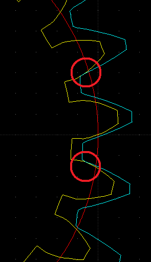
Now, at least to me, the gears are meshed (no backlash) but the contact is between the outer teeth, not the centre tooth (see image below):
![]()
All the other 1/10 tooth rotations are similar.
The next rabbit hole?
The contact area is mostly on the low area of the planet and high area of the ring. These are not important areas (I think?) for normally meshed gears. The meshing may be improved by trimming the high area of the ring gear.
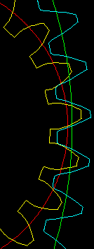
Ideally the pitch circle of the planet and the ring gear should touch (the red and green circles):
![]()
So the plan would be to set the ring gear pitch circle to touch the planet pitch circle, and then "trim" the ring gear top of tooth area until there is no interference (for 1/10 tooth rotations).
Need to work out how to code "trim". Hopefully an easy fix for the Make Gear code pops out of the experimentation.
Results or Any Easter Eggs?
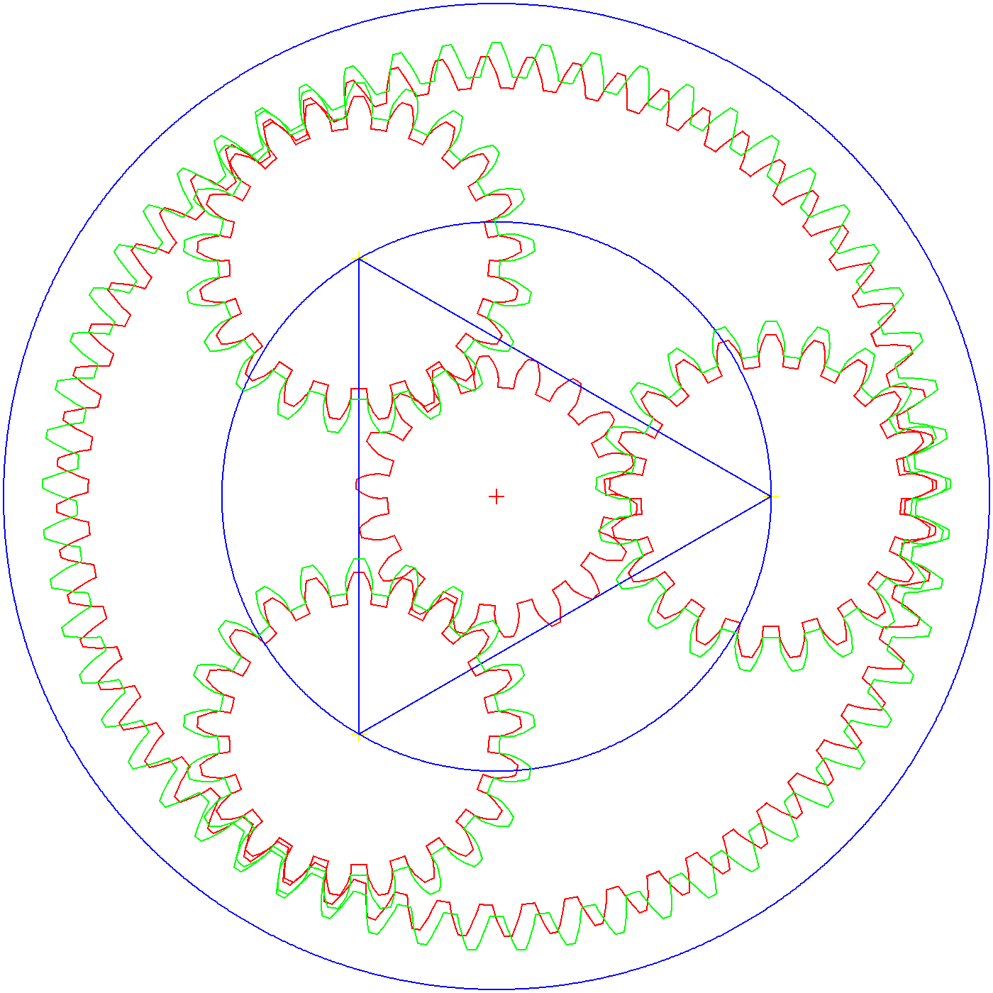
After a long day hacking my code, here is a solution:
![]()
Note the white line. It is to show how straight the tooth profile.
Optimality?
Now, is it optimal, can I do better? What are the results telling me?
And the answer is not "42" as it has 57 teeth!
Like usual I have to sleep on it.
The Answer
The answer is that the gear pitch circles are not valid!
- As the gear is locked it has to rotate 57 to 21, and the gear pitch circles are not in this ratio (as their Diametric Pitch (DP) are different).
- The effective pitch circles have to be 57 to 21.
- So the teeth have to contact either side of the centre, where the effective pitch circles must overlap or cross.
For tooth clearance purposes, using the gear pitch circles for gear design is appropriate.
So in conclusion, the design is now fully constrained and zero backlash, optimal by our definition.
Note, as I trim gear teeth for interference, the pressure angle is no longer important.
Universal Epicycle Gear Formula
I found the universal epicyclic gear formula:
- Tc*(Ns+Nr)=Ts*Ns+Tr*Nr
Okay, I rearranged it a little to suit my tastes.
- Ts = Turns in the Sun
- Tc = Turns in the Carrier
- Tr = Turns in the Ring
Note: The Planets play not role
- Ns = Number of teeth on the Sun
- Nr = Number of teeth on the Ring
Basically, you set Ns and Nr, and two of the three Ts, Tc and Tr, and solve for the unknown.
Let's try Daren's design:
- Ns=18
- Np=21
- Nr=60
Note: Nr=Ns+2*Np
- Ts=1 (one turn)
- Tr=0 (fixed)
Therefore:
- Tc=(Ts*Ns+Tr*Nr)/(Ns+Nr)
- Tc=(1*18+0*60)/(18+60)
- Tc=18/78 (=1/4.333)
Next Stage:
- Ns=18
- Np=21
- Nr=57
- Ts=1 (one turn)
- Tc=18/78
- Tr=(Tc*(Ns+Nr)-Ts*Ns)/Nr
- Tr=(18/78*(18+57)-1*18)/57
- Tr=(18*75/78-18)/57
- Tr=-0.01214575 =(-1/82.333)
A reduction ratio of -82.333 was the previous calculation.
AlanX
-
Gear Calculations
04/19/2019 at 09:14 • 1 commentGear Calculations
I could not be bothered tying to work this out, someone has done it before, I just have to find it.
On my search journey I found the gear system we are using are call Epicyclic gears.
Anyway I did find a website that published the equation for this specific gear system (http://www.efunda.com/DesignStandards/gears/gears_epicyclic_train.cfm).
If the gear train is Na/Nb/Nc and Nd/Ne (i.e. Sun1/Planet1/Ring1 and Planet2/Ring2) where Ring1 (Nc) is fixed ,and the planets (Nb and Nd) are locked the the reduction ratio is:
- R=(1+Nc/Na)/(1-Nc*Nd/Nb/Ne)
Here is the worked example from the website:
Gear Train – Worked Example NA 21 Sun 1 Driven NB 61 Planet 1 Locked to Planet 2 NC 141 Ring 1 Fixed ND 41 Planet 2 Locked to Planet 1 NE 121 Ring 2 Output Gearing 1 7.7143 Check Gearing 2 0.2168 Check Gearing 0.0281 Check Reduction 35.5870 Here is Daren's design:
Gear Train – Daren NA 18 Sun 1 Driven NB 21 Planet 1 Locked to Planet 2 NC 60 Ring 1 Fixed ND 21 Planet 2 Locked to Planet 1 NE 57 Ring 2 Output Gearing 1 4.3333 Gearing 2 -0.0526 Gearing -0.0121 Reduction -82.3333
Note the sign change in the reduction ratio, this appear to be correct.And here is my five planet version:
Gear Train – Alan v2 NA 25 Sun 1 Driven NB 20 Planet 1 Locked to Planet 2 NC 65 Ring 1 Fixed ND 20 Planet 2 Locked to Planet 1 NE 60 Ring 2 Output Gearing 1 3.6000 Gearing 2 -0.0833 Gearing -0.0231 Reduction -43.2000 Realisation
The gear design has migrated such that the requirement for the two planetary gears to have the same number of teeth is no longer valid.
AlanX
-
Conceptual (Laser Cut) SCARA Elbow Design
04/19/2019 at 04:31 • 6 commentsLibreCAD
I am migrating from DeltaCAD to LibreCAD. So far LibreCAD has proved to be stable.
The DeltraCAD user interface is much better than LibreCAD from the point of view of minimum mouse/hand movements and less steps to do things. I should point out that DeltaCAD is not an AutoCAD clone. LibreCAD is slower to use as most things need more steps. If you use CAD all day you will appreciate keyboard short-cuts (avoiding menu mouse movements) and minimal steps. Especially as you get older.
Other issues are that some of the commands are not functional are rather primitive, "Polyline Equidistant" is an example. Can't expect everything for free!
As I have to run DeltaCad under Wine, losing the macro language and the fact it does not support PolyLine (only lwPoyLine), I have to migrate.
(Well I could use VM VirtualBox and Windows with DeltaCAD!)
Changes to the Gear Ratios
I want make the elbow as compact as practical but the current Sun gear is too small for the stepper motor hub. Rather than increase the overall gear set size, I have changed the gear ratios to make the Sun gear larger (and the Planetary gears smaller) without chaning the outer diameter.
I am now using 24/18/57 and 18/57 gear ratios.
I also increased the Diametral Pitch to 1.0 and 0.928571429. This reduces the size of the gear set to ~75 mm diameter.
To calculate the Diamteral Pitch ratio use (57-21)/(60-21).
Laser Cut Design
The design is built up in layers using 6mm thick MDF. A single layer was no really good enough for the SCARA Prototype. The thickness need to be at least doubled.
The final design will have 1 mm alignment holes and glued in most cases.
Where disassembly is required M3 bolts will be used to hold the pieces together.
Bearing surfaces need to be lubricated with wax or silicon spray. However a paper spacer most likely will be required to give some bearing clearance. Other bearing types (teflon?) may be considered later.
The laser cut diameter for the guy I use is about 0.1 mm. The cut quality varies, sometimes he cuts too slow, sometimes his machine is out of alignment. Given the gear teeth are quite small, an allowance for this probably should be made. LibreCAD's polyline offset does not work so I will have to make this adjustment in the gear code.
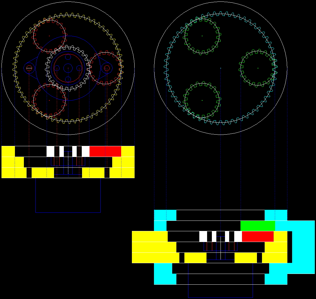
Here is my preliminary design. The lower layer is optional but is designed to increase the joint stiffness:
![]()
Notes:
- The yellow layers are the left arm and the cyan the right arm.
- The "gaps" in the layers are provision for mounting bolts.
- The blue outline is a Nema16/17 stepper motor and mounting hub.
- White, red and green are the inner gears.
- If I did not have to make allowance for the stepper motor mounting bolts, the drop down into the layer with the hub, reducing the elbow thickness by two layers.
Planetary Gear Retainer or Cage
It is possible to add a 6 mm thick planetary gear retainer in the upper layer or a 3 mm thick retainer in the hub layer. It is assumed the retainer axles are not concealed.
At this point of time I don't really thick they are needed in this application.
Using Acrylic
Acrylic (perspex) is nice looking material but has some undesirable properties.
- It not very stiff and it stress fractures over time.
- And special glues are required.
I suspect there a different grades of acrylic and the stress fracturing is a feature of the cheaper grades.
If the MDF version work out okay I may look at an acrylic version.
More Planetary Gears
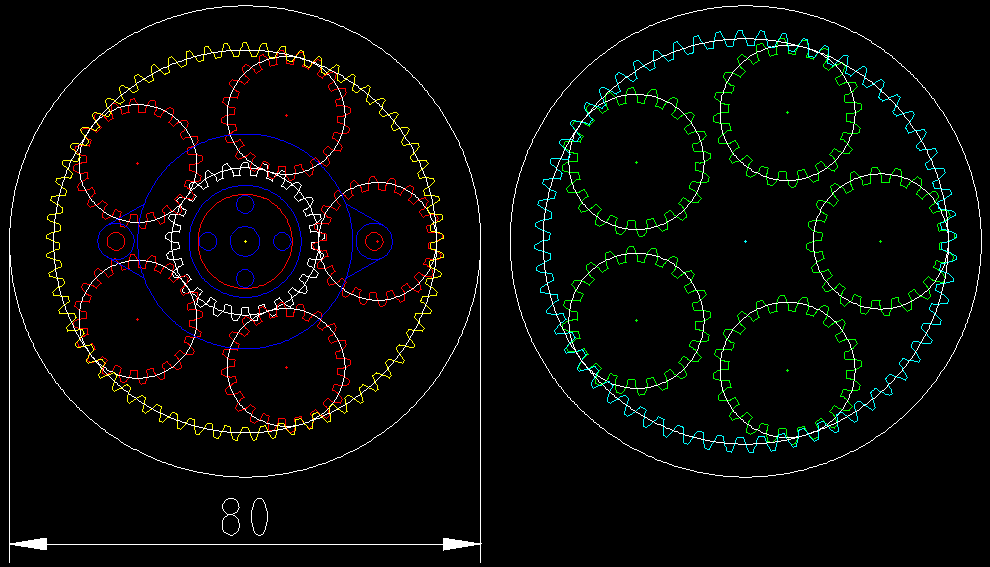
It is possible to add more planetary gears by changing the outer gear ratios. It seems like a good idea. I had a play and I came up with a five planet design (25/20/65 and 20/60). I set the outer gear diameter to 80 mm. Still using a first Diametral Pitch of 1.0 (i.e. gear teeth are 3.14 mm apart):
![]()
Retaining Ring
I may as well design the retaining ring for the planets. I can try with and without. I will put it in the top layer (above the green planets in the image above).
Next Step
I think I am ready to detail the elbow design for manufacture. The five planet design will have a less reduction than the three planet design.
AlanX
-
Properly Meshed Planetary Design
04/16/2019 at 13:07 • 1 commentProperly Meshed Planetary Design
For this log I present a properly meshed planetary drive:
![]()
Notes:
- The red gears are the first layer and the green gears are the second layer.
- Only the first layer has a Sun (pinion) gear.
- The planetary gears (red and green) are locked to each other (they do not rotate independently of each other, i.e the layers are fixed to each other).
- The outer layers rotate freely of each other.
Generating the gears
Initially I used Gearotic (as I have a licence) but Gearotic is tricky to use if you have not used it for a while and the exported DXFs are not great. And the gears are not one shape (each). The are short "polylines".
While this was not a problem in the past when I was using Windows because I had a macro for my CAD package that could join the polyline segments. Unfortunately the macro feature does not work under Wine (as I have migrated to Linux).
In the end I decided to write my own gear code in C and export my own DXF gears.
DXF File Format
The DXF file format is an absolute nightmare. While exporting points and segments are easy, exporting polylines (i.e. shapes) that CAD packages can read in is not.
I found some old code that I have written for polylines and thought great, lets try this.
Well yes, it imports into my CAD package but my CAD package converts the polylines to segments. Not good.
I found some more old code that I have written for lwpolylines and thought great, lets try this. Well it was unfinished, I was having problems with the "handles" and never solved it.
Then I though, perhaps the problem with polylines is my CAD package. So I installed LibreCAD and yes it imports the polylines properly. LibreCAD does not have a macro language but as it can import polylines, segments and points it does not matter if I can created simple DXF files in C. Move over DeltaCAD, LibreCAD coming through.
Gear Code
I will upload the gear code later, it still needs a user interface. But I have uploaded the DXF file. If the gears are the wrong size you can just re-scale them.
Top Level Code for the MPRT Concept
This is for reference:
{ // Top level Gear Code
  double PA=20.0;                               // Pressure angle
  double P=0.10;                                // Diametral Pitch
  double TX=0.0;
  double CX=0.0;
  double CY=0.0;

  // First Gear Set
  makeGear(2, 18,PA,P,CX,CY,0.5);              // Sun, rotate 1/2 tooth for mesh
  CX=(60-21)/P/2;
  CY=0.0;
  makeGear(2, 21,PA,P,CX,CY,0.0);              // Planet 1
  TX=CX*cos(120*M_PI/180)-CY*sin(120*M_PI/180);
  CY=CY*cos(120*M_PI/180)+CX*sin(120*M_PI/180);
  CX=TX;
  makeGear(2, 21,PA,P,CX,CY,0.0);               // Planet 2
  TX=CX*cos(120*M_PI/180)-CY*sin(120*M_PI/180);
  CY=CY*cos(120*M_PI/180)+CX*sin(120*M_PI/180);
  CX=TX;
  makeGear(2, 21,PA,P,CX,CY,0.0);               // Planet 2
  makeGear(2,-60,PA,P,0.0,0.0,0.0);             // Outer ring

  // Second Gear Set
  P=P*(57-21)/(60-21);                          // Change Diametral Pitch
  CX=(57-21)/P/2;
  CY=0.0;
  makeGear(3, 21,PA,P,CX,CY,0.0);               // Planet 1
  TX=CX*cos(120*M_PI/180)-CY*sin(120*M_PI/180);
  CY=CY*cos(120*M_PI/180)+CX*sin(120*M_PI/180);
  CX=TX;
  makeGear(3, 21,PA,P,CX,CY,0.0);               // Planet 2
  TX=CX*cos(120*M_PI/180)-CY*sin(120*M_PI/180);
  CY=CY*cos(120*M_PI/180)+CX*sin(120*M_PI/180);
  CX=TX;
  makeGear(3, 21,PA,P,CX,CY,0.0);               // Planet 3
  makeGear(3,-57,PA,P,0.0,0.0,0.0);             // Outer ring
}
"makeGear" parameters are:
- Colour
- Number of teeth
- Presure angle (degrees)
- Diametral pitch
- Gear X centre
- Gear Y Centre
- Gear rotation as a fraction of a tooth
Next
Now that I can design the gears for the MPRT, I can now look at the SCARA elbow design.
AlanX
-
Github up.
04/14/2019 at 04:37 • 0 commentsCreated a Github repo and uploaded the latest.
This will likely change pretty shortly..
-
Introduction - AlanX Collaborator
04/12/2019 at 03:28 • 9 commentsMPRT Project
Introduction
The MPRT project is both very interesting (for those who appreciate mechanical things at least and/or robotic) and useful. It is particularly useful for SCARA robots. This is my interest.
I have a Prototype SCARA project (https://hackaday.io/project/164066-prototype-scara) that uses direct drive stepper motors. I want to upgrade to geared drive. I have designs for belt drive but then the MPRT project came along.
Whats to Like?
Relatively simple, compact and high gearing ratios and potentially (to be demonstrated) low backlash. Ideally suited to a SCARA elbow.
Whats not to Like?
Not an off the self product, needs quite a bit of research, and trial and error to get it right.
Collaboration
My collaboration will be in part shared work with Daren, and parallel work focusing on a laser cut version (Daren is focusing on 3D printing) for my Prototype SCARA project:
Today
An Alternate Arrangement
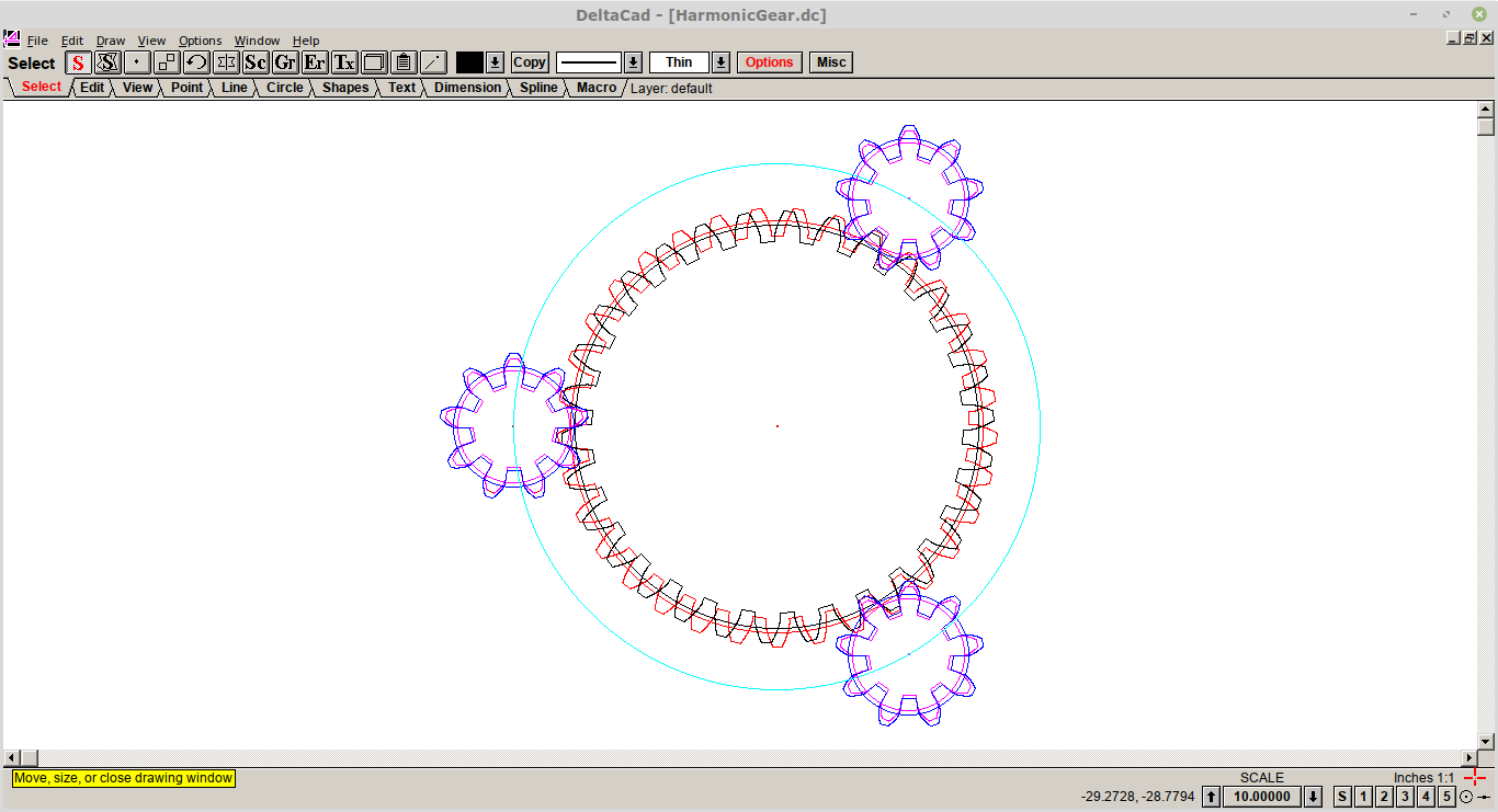
As I am looking at low backlash (and understanding Daren concept better), I put forward an alternate arrangement:
![]()
The concept is not a full design so you have to use your imagination.
The concept here is a driven planetary ring (cyan circle and the three planet (pinion gears)) and driving the two separate centre rings.
Notice that the planetary gears are linked by the cyan ring and the planetary rings consists of two sandwiched and locked gears that drive the two centre (sun) separately (unlocked).
Although it looks completely different to Daren's concept is is basically just a rearrangement.
In operation, the planetary gears turn and rotate around the sun, but locked to where the sun gears align. As the Sun gears have different number of teeth they have to rotate at different speeds to meet the planetary gears.
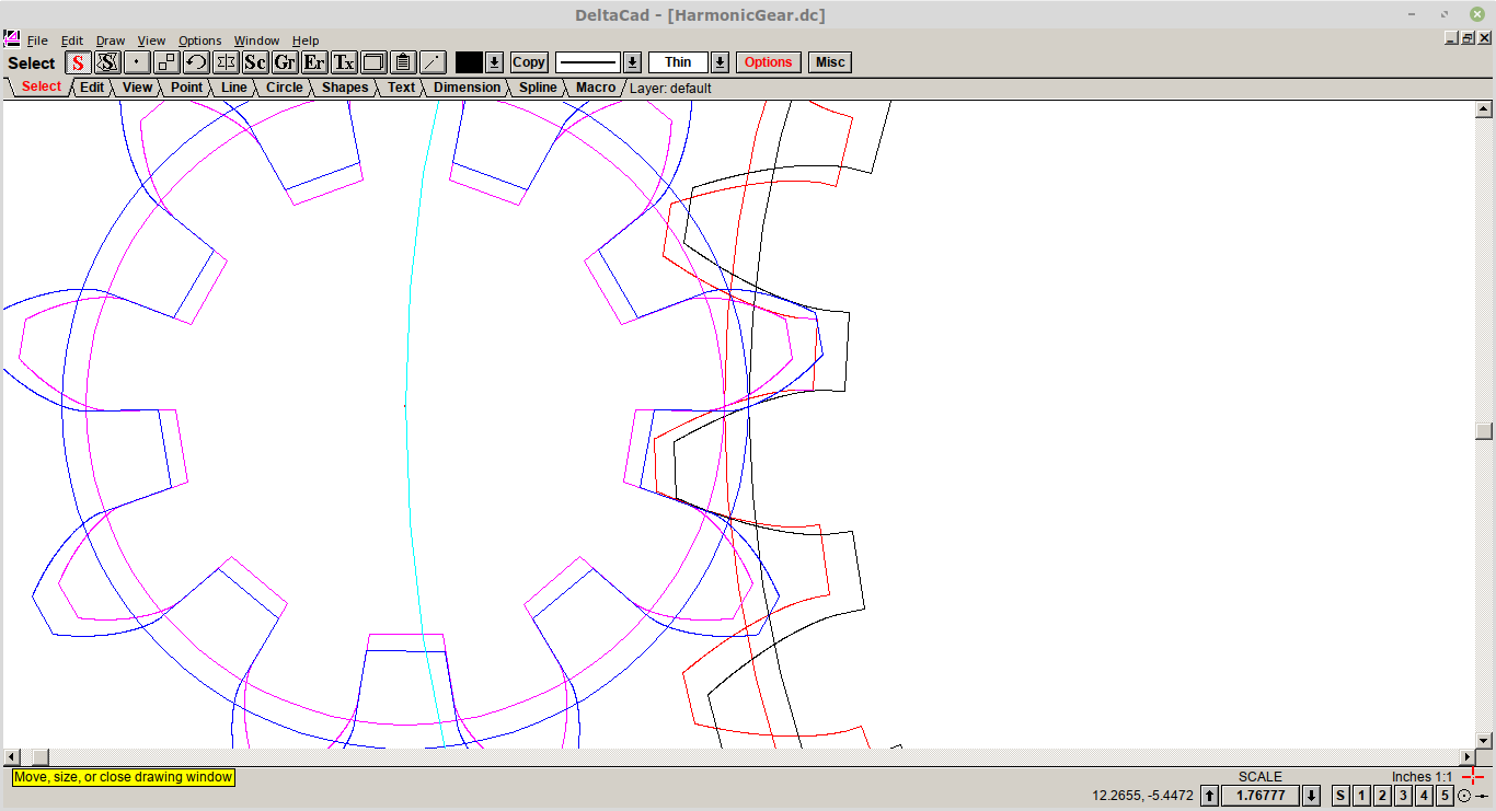
Now let us look closer:
![]()
You should be able to see the blue and black gear pair, and the magenta and red pair, superimposed on each other.
You can see these gears are tightly meshed, no compromise.
Construction and design of the gears is very straight forward (no tricks required).
As an aside, I am using DeltaCAD, a cheap ($50) and really nice 2D CAD package. It comes with a macro language that I used to create my gears.
SCARA Elbow Design Concepts
Well this will be the topic form my next post.
AlanX
-
The plan.
04/09/2019 at 19:44 • 4 commentsModel a spring loaded split planet to eliminate backlash. The split will be across the diameter and provide force in one direction. This will spring it against the rotation of the other two planets, eliminating backlash.
<EDIT> Little problem here. The other side of my split planet would be meshing with the sun gear. I would like to keep the sun gear full height as it keeps the forces nicely aligned so I don't need bearings for them.
@Simon Merrett has a decent idea for making the planets slightly 'springy' themselves all the way around their circumference, and then ultimately making them slightly oversized to keep the tight fit. I could probably just print them in nylon and make them have an empty center and get the same effect, but over-torque could make them bend too much and slip. Perhaps a ring connected to a solid center by spiral arms...
</EDIT>
The challenge is coming up with one I can laser cut. A 3D printed version will be pretty simple.
I would also like to try to *lower* the gear reduction a little. 66:1 is a little excessive and prevents fast motion without really high speeds.
-
Video!
04/08/2019 at 03:41 • 0 comments -
Something useful.
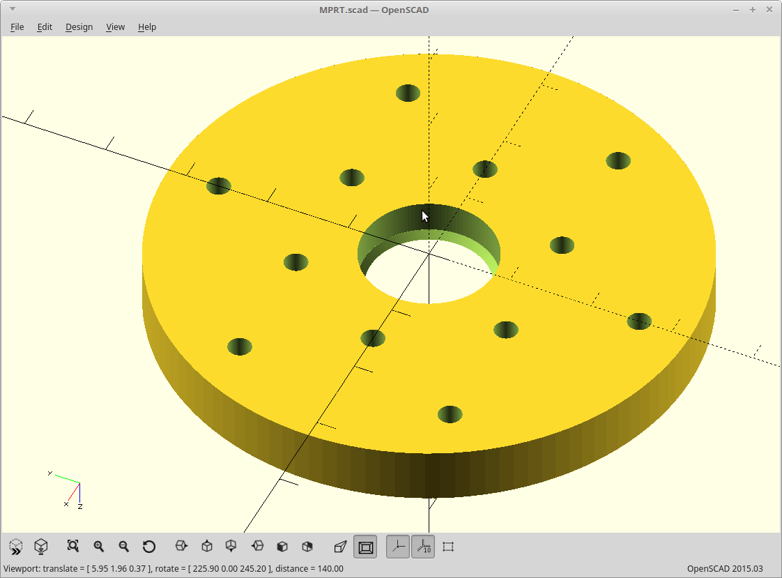
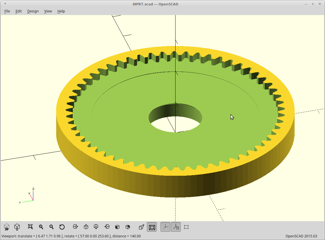
04/07/2019 at 21:01 • 0 commentsI changed my mind and made the output ring gear something you can actually use right now by adding a bearing.
It breaks the laser cut equal height paradigm, but that could easily be undone by splitting it into three layers.
These three layers are all solid with your output anyway, and so could be modeled to be directly be part of your 'arm'.
![]()
![]()
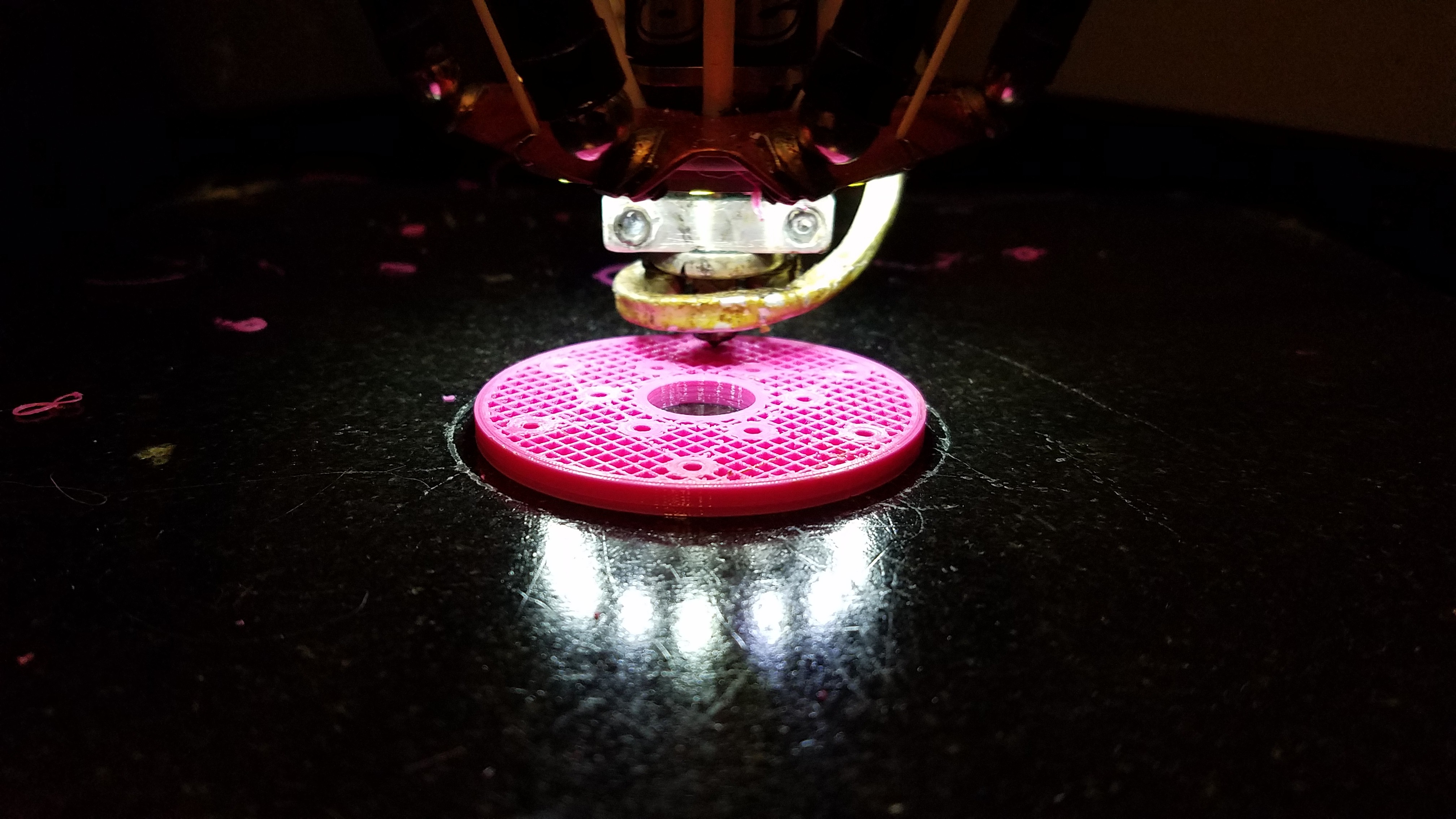
Printing...
![]()
-
The needful.
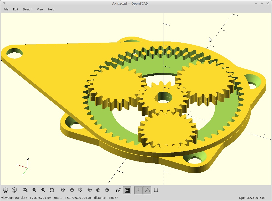
04/07/2019 at 07:59 • 0 commentsCleaned up the source a lot. New source is uploaded.
Brought the 'involute_gears.scad' script up to date with the current state of OpenSCAD to eliminate warnings.
Made wall thickness a variable.
Added recesses for stepper screws.
![]()
Printing.
<EDIT>
Changed my mind. See next log
</EDIT>
MPRT - Modified planetary robotics transmission
The reduction of strain-wave, but using a 'single' stage planetary gearset.
 Daren Schwenke