Close
0%
0%

Simple bipolar full step driver

A simple bipolar step motor driver, the goal here was to use simple components, without any dedicated IC, and produce a single layer PCB

Similar projects worth following
This project was actually designed by me to be used as an exam for my students in a competition called WorldSkills Asia. It's a open source project so I'm happy to share it with you guys. The goal was to design a step driver using some classic components, easy to find at any electronics shop.

A bipolar driver can push 100% of the motor torch and to create two H bridges I've used the classic L298. All digital ICs were CMOS that can reach up to 15V, and I've used some open collector comparators to avoid high frequency noise from switching the driver's enable pin.
Something I really regret about this circuit was not using a diode or MOSFET to avoid an inverted connection at the power inputs.

Some other feature here was the possibility of building the board using a milling machine. I've made a single layer design with a few jumpers.

It's simple, but works well if you want speed instead of micro stepping, it can reach 4A without any problems :)

Briefing

Alright, all starts from our features/reason list:

  • Full step, to assure maximum torch all time and use a lower number of parts;
  • Total controlled current up to 4A (maximum current of L298);
  • Bipolar architecture, to assure maximum torch efficiency;
  • Cheap not-isolated command (common ground);
  • Motor input voltage 7-40V;
  • Digital inputs from 3.3 up to 15V (or up to 5V if TTL compatible ICs are used);
  • Jumper to revert input’s signal direction.
  • Non programmable devices (because it's fun).
  • Adjustable current to be suitable for several motors.

Now we can draft a small system overview, to see all inputs and outputs and also the user interface:

System overview

Blocks diagram

Considering I'm happy with it, I could create a small blocks diagram:

Blocks diagram

When I do the blocks diagram, usually I have in mind some components and try to track the number of ICs for different solutions, this is actually my favorite part. As I was using only CMOS logic, I use the wikipedia list of 4000 family, and the second place is the supplier (RS, digikey, mouser, etc), just to check the price among different compatible options.
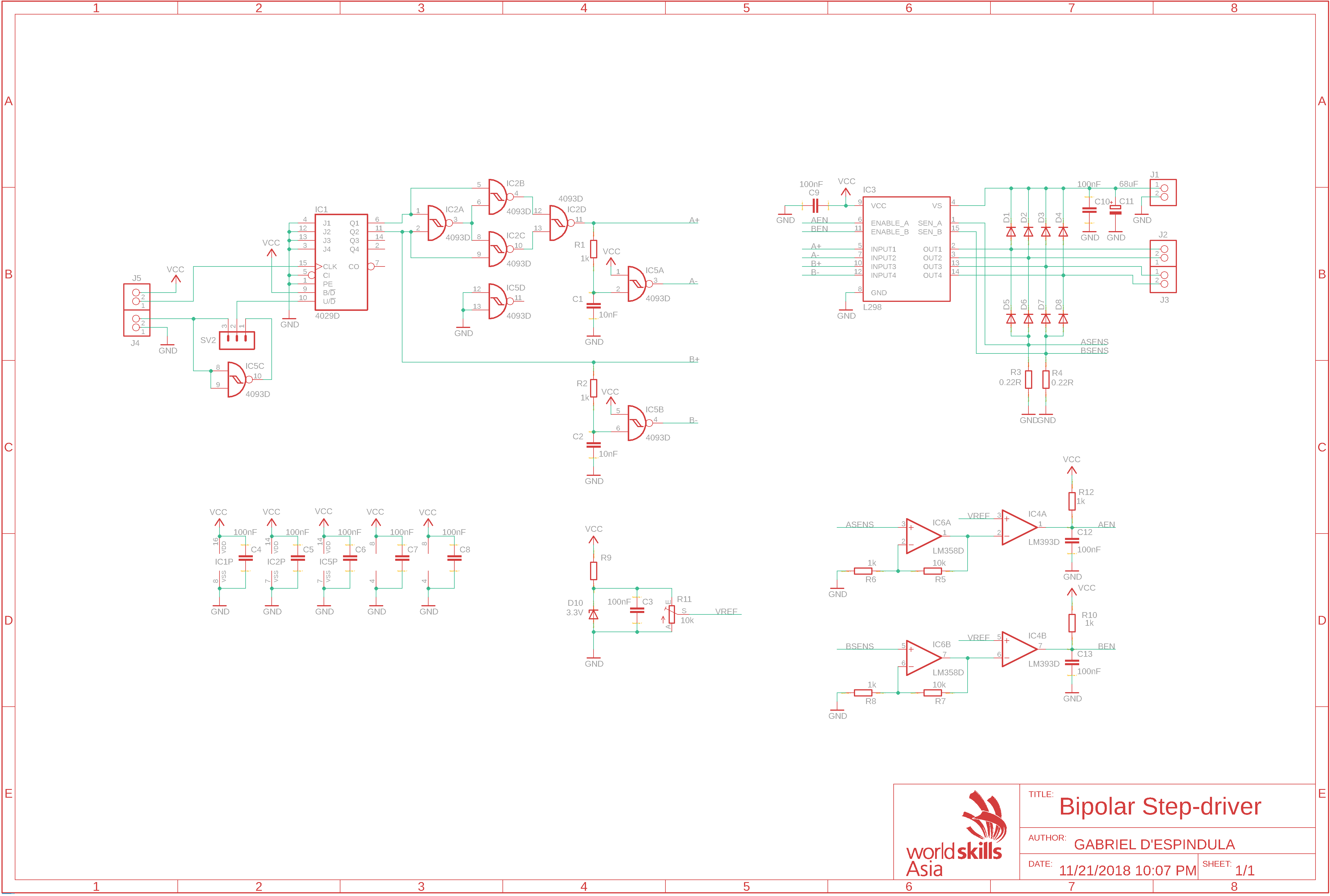
Schematics


Turns out I came up with this circuit:
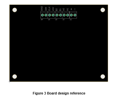
PCB

Finally, the board.
For this project, I've set some rules as following:

  • Minimum clearance: 15mil;
  • Minimum trace width: 15mil;
  • Minimum via diameter: 1.27mm and 0,711mm hole;
  • Board exact size: 95x75mm;
  • 4mm holes on each corner. The centre of every hole is 5mm distant from the edges;
  • The maximum number of jumpers is 30. More jumpers will deduce some points;
  • The connectors must be attached together, aligned side by side, with a clear area between them and the board outline, to provide space for wires. Bellow there is an explicative illustration:

:D

Bipolar Step-driver.sch

Eagle Schematics

sch - 1.13 MB - 04/04/2019 at 12:22

Download

brd - 469.02 kB - 04/04/2019 at 12:22

Download

Bipolar Step-driver.pdf

Schematics in PDF

Adobe Portable Document Format - 43.07 kB - 04/04/2019 at 12:21

Preview
Download

Step-driver BOM.xlsx

Bill of materials

sheet - 12.56 kB - 04/04/2019 at 12:21

Download

  • 1 × Pin header 1x3 2.54mm pitch pin male straignt pin header
  • 8 × SR560 Discrete Semiconductors / Diodes and Rectifiers
  • 1 × Several resistors
  • 5 × Terminal block Connector 3.5mm pitch
  • 1 × Several capacitors

View all 12 components

  • Improvement points

    Gabriel D'Espindula04/04/2019 at 12:25 0 comments

    The project works well, I would change a couple things for the next version:

    1. Add a diode or P-Channel MOSFET to avoid inversion of the power supply;
    2. Change the input connector's silk, the way it is all wires are in front of the text, would be better to see the signals even with the wired hooked up.

View project log

Enjoy this project?

Share

Discussions

Similar Projects

Does this project spark your interest?

Become a member to follow this project and never miss any updates