Close
0%
0%

BitsyLED

A minimal firmware and configurator to drive RGB LED's

Public Chat
Similar projects worth following
BitsyLED is a minimal firmware to drive RGB LED's (WS2811, WS2812, NeoPixels, etc). It's designed for anything RC but also can be used for other projects including Christmas lights, Lego's, or even your real car.

BitsyLED is divided into two parts: The Firmware and the Configurator. The firmware can be run on most Arduino compatible boards and I also created a dedicated board that is targeted primarily for RC purposes and can be ordered from Oshpark.

The idea behind BitsyLED is that I was tired of building firmware after firmware for simple light sequences and told myself that this needs to be easier. The firmware is built on CDD (Configuration Driven Design) principles and supports different patterns, speeds and of course colors - all easily configurable through the dedicated desktop app.

This project is available on GitHub (https://github.com/flyandi/BitsyLED) and is 100% open source.

Since this is original targeted towards RC; I created an official thread on RCGroups at https://www.rcgroups.com/forums/showthread.php?3289805-BitsyLED


INTRODUCTION

In a nutshell: BitsyLED is a software/hardware package that allows to drive RGB led's of various types with just simple configurations.


FEATURES

  • Individual ranges, selectable through either an RC PWM signal, Analog signal, Time based or Always on mode
  • Multiple LED data strands per range
  • Each data strand can have multiple LED's attached to it
  • Supports multiple patterns such as Off, Solid, Blink, Strobe and Pulse.
  • Supports different speeds per pattern
  • Simulate your patterns directly through the BitsyLED configurator

SOFTWARE

BitsyLED comes with two software pieces: The Firmware and the Configurator. 

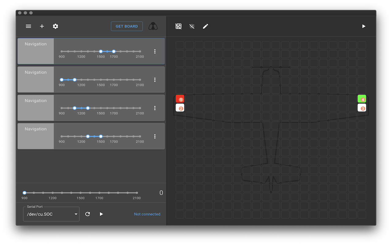
The Configurator allows to visually configure and setup LED's. The configurator is a standalone application available for Windows, Linux and Mac. The app itself is written in React + Material UI and packaged in Electron. 

The configurator manages unlimited amount of configurations however only one configuration can be uploaded to the actual Hardware.

The firmware and the configurator both encompass the same philosophy where each configuration can have multiple Ranges. A range defines the layout and configuration of a specific set of LED's. The range itself can be configured to be selectable through either RC PWM, Analog, Time based or Always On signal. As a bonus the configurator will highlight the selected range if a board is connected.

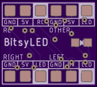
Each range can have a certain amount of LED data strands (usually 3: Left, Right, Other). A Strand is the physical data channel on the Hardware side where the LED's are connected to. 

Each strand has a defined amount of maximum LED's.
I am in the process of making some how-to videos that I will post here soon.


HARDWARE

The BitsyLED firmware is compatible with most Arduino compatible boards however to simplify things I have aligned the Arduino base configuration for the Arduino Pro Mini. Some boards may support more ranges, strands and LED's but that's up to configure.

As an alternative I have created the BitsyLED Board specifically for RC and it's available to purchase from Oshpark (https://oshpark.com/shared_projects/B3IAiNyH).

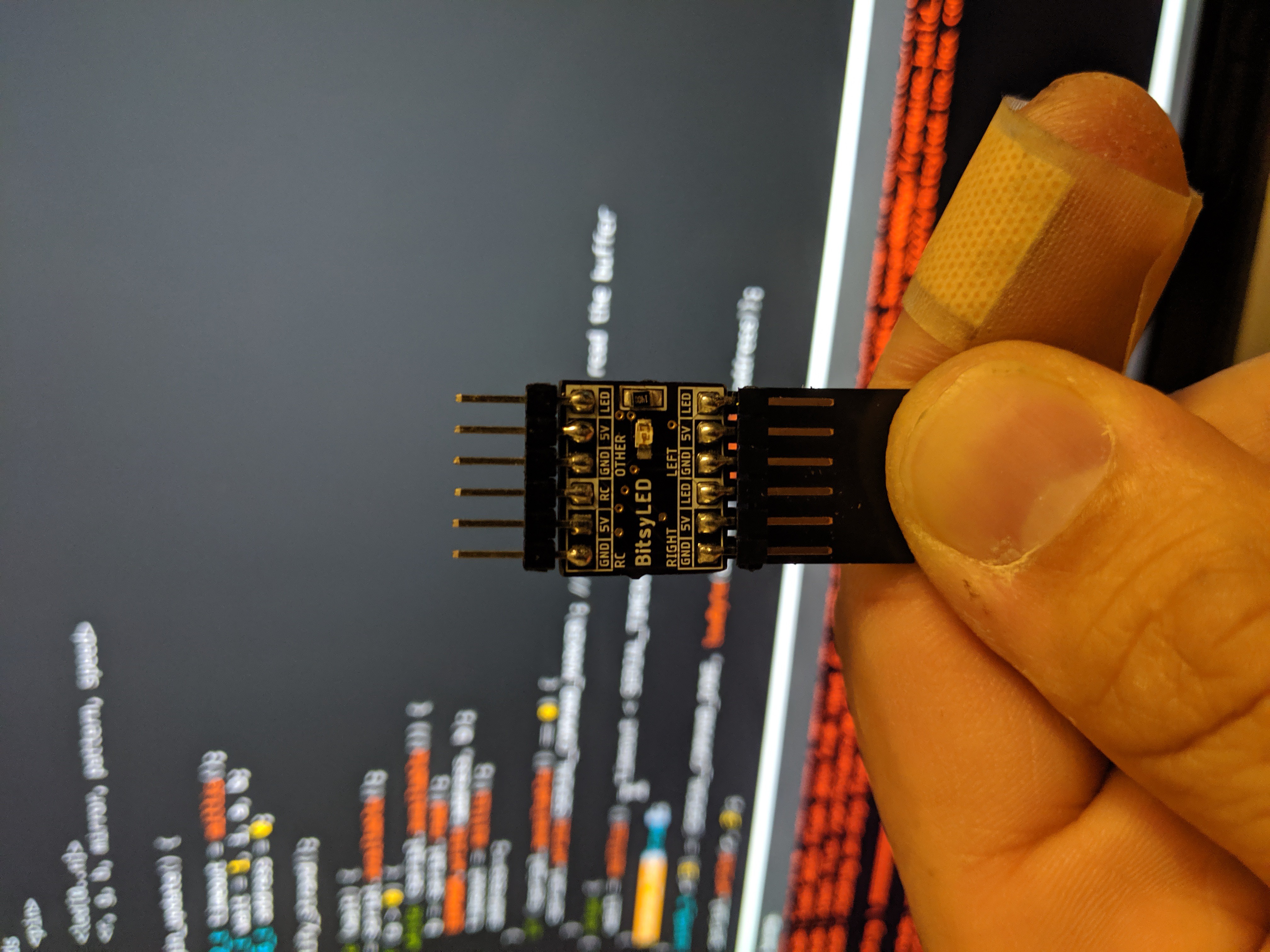
I choose to power the BitsyLED board with an 8Bit ATTINY84 because it's still easy to solder it and only uses a few extra components. The firmware settings are optimized for the ATTINY84 and can support up to 5 ranges, 3 strands and up to 10 led's / strand - running flawlessly without memory issues.
  • 1 × ATTINY84 Part ATTINY84A-SSURCT-ND)
  • 1 × 805 Capacitor Part 587-1304-1-ND
  • 1 × SOD-123 Diode Part MMSZ5231B-TP
  • 1 × Blue LED in 805 packaging 150080BS75000
  • 1 × Resistor in 805 packaging with value of 140ohms RMCF0805FT140R

  • Firmware 1.04 and Configurator 0.6.5 released

    Andy09/15/2019 at 06:35 0 comments

    Latest updates from the BitsyLED development efforts - After not having time for a couple months for this project, I finally could catch up on some lingering issues and released a new firmware and configurator.

    This release ensures that the firmware and configurator is wired for the 1.2.1 boards by default (was still in 1.1 mode). Also I made some improvements on the serial communication interface and added some safety when writing the data into the EEPROM. This should fix the issues around locking up for a while. Tested it with about 50 writes to 1.2.1 board and it didn't lock up or was unstable.


    Get it now on Github at https://github.com/flyandi/BitsyLED/releases/tag/v0.6.5

  • Firmware 1.03 released

    Andy05/12/2019 at 05:15 0 comments

    A new firmware for BitsyLED was released. 

    1.03 includes full status led support as well enables status led support for the BitsyLED board 1.2.1.

  • BitsyLED 1.2.1 boards have arrived...

    Andy05/12/2019 at 04:49 0 comments

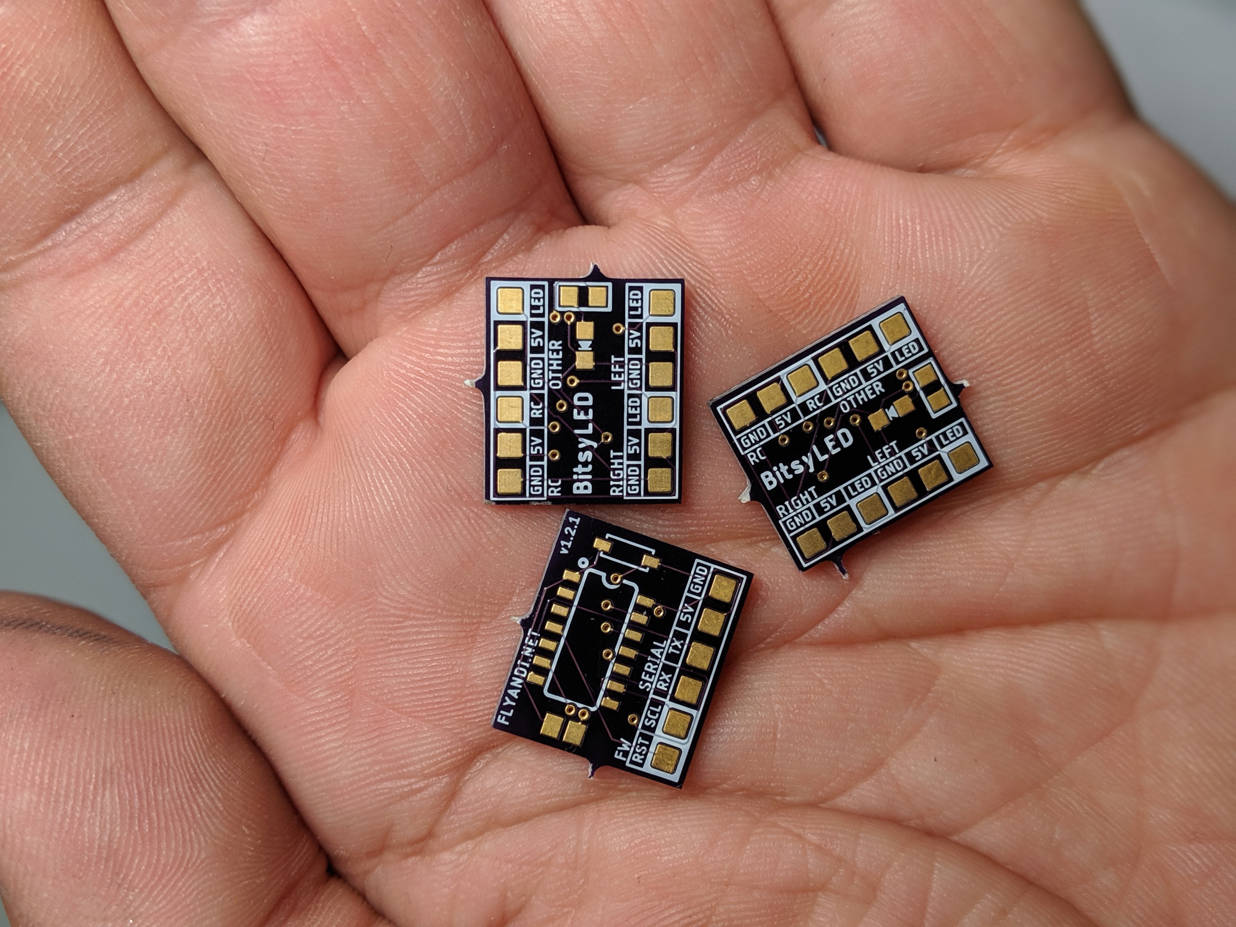
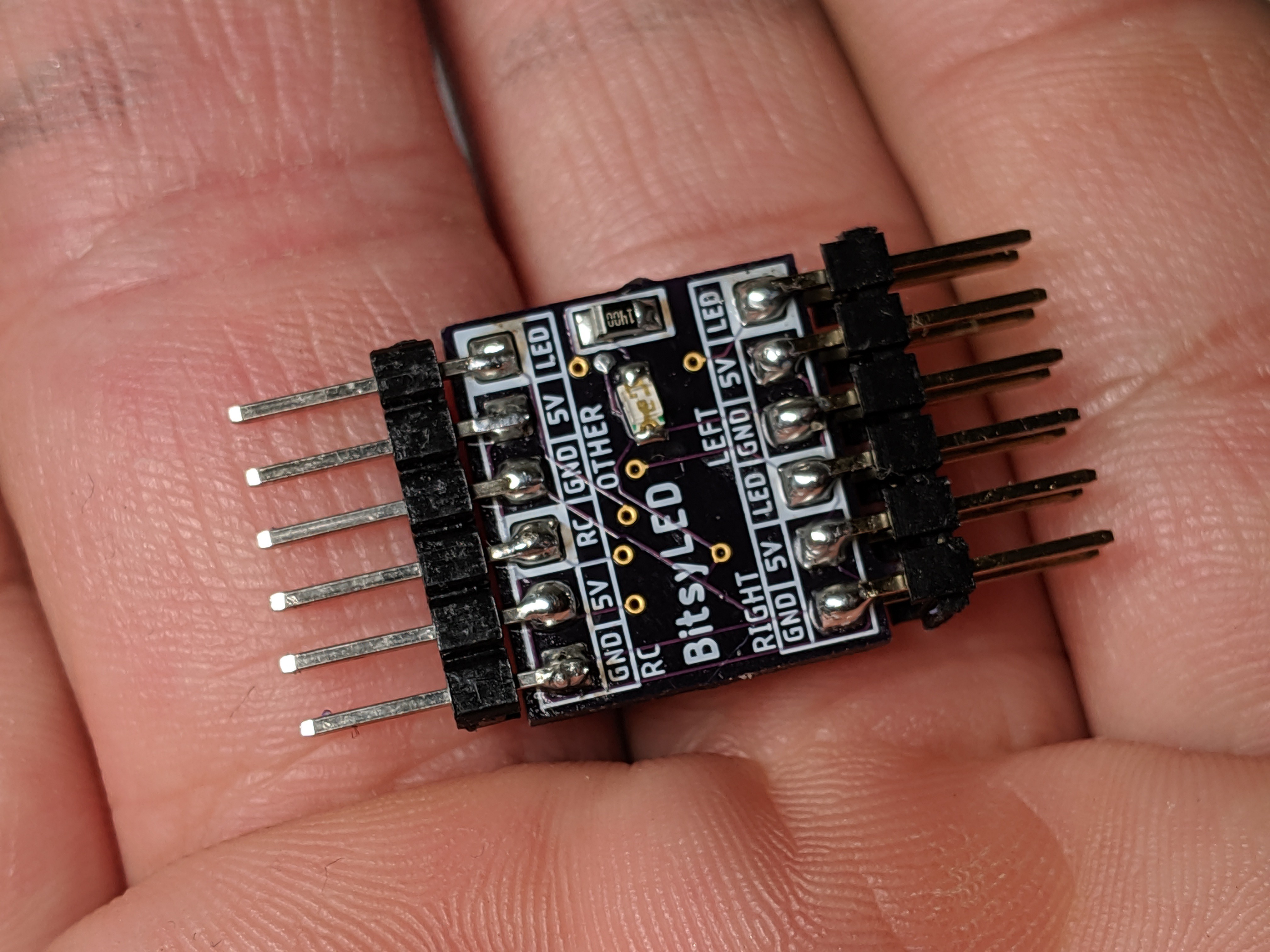
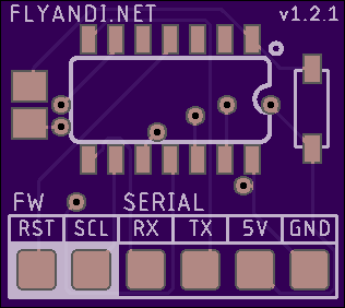
    Finally - my 1.2.1 boards are back from Oshpark and they look good! The footprint of this version is truly tiny but still easy to solder thanks to the 805 SMD component size. 

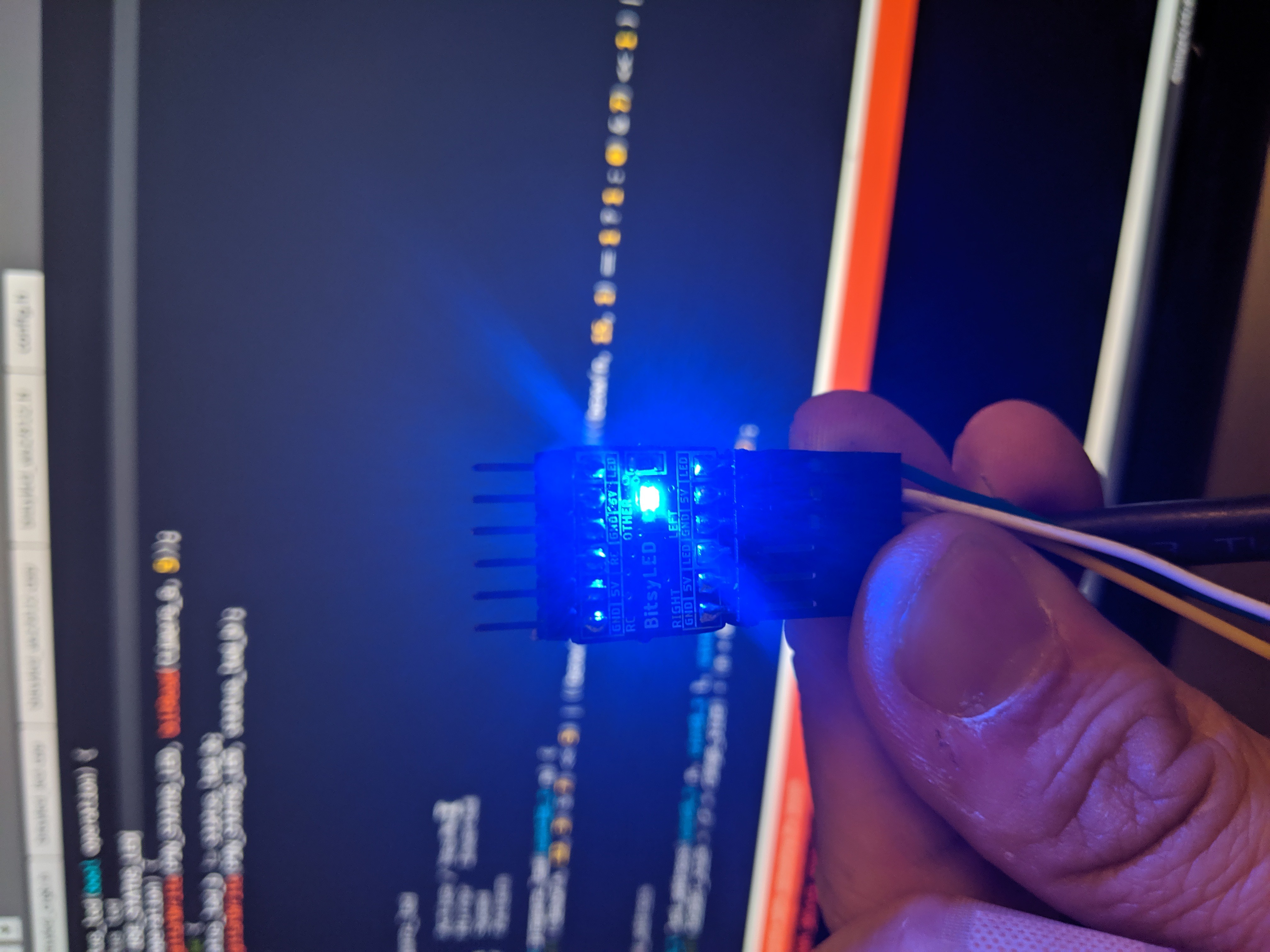
    I also added finally an status LED to see if the board is properly responding.

  • Configurator 0.6.2 released

    Andy05/02/2019 at 03:21 0 comments

    The BitsyLED Configurator 0.6.2 is released which includes the presets library for an easier start.

    Also did some bug fixes that were annoying like disappearing ranges, etc. 

    Download the latest release at https://github.com/flyandi/BitsyLED/releases/tag/v0.6.2 for your platform.

    If you have the app already installed, you don't have to worry and the update will be installed automatically.

  • BitsyLED Board 1.2.1

    Andy04/30/2019 at 04:11 0 comments

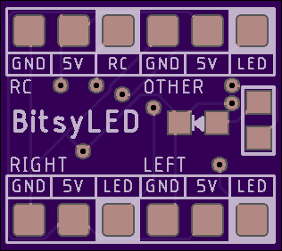
    I cleaned up the 1.2 version and created v1.2.1. The board is available at https://oshpark.com/shared_projects/B3IAiNyH and will be my last revision for now.

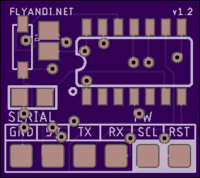
    I created a new board that is slimmer and has SMD pad's instead of the drill pad's which gives it more flexibility. The board also comes with a status LED.

    Parts

    All parts available on DigiKey.com. I changed some components in this version!

    • 1x ATTINY84 (Part ATTINY84A-SSURCT-ND)
    • 1x Capacitor in 805 packaging (587-1304-1-ND)
    • 1x Diode in SOD-123 packaging (MMSZ5231B-TP)
    • 1x Blue LED in 805 packaging (150080BS75000)
    • 1x Resistor in 805 packaging with value of 140ohms (Part RMCF0805FT140R)

  • BitsyLED Board v1.2 Slim

    Andy04/27/2019 at 08:30 0 comments

    I created the next revision of the BitsyLED board. It's smaller and has now SMD pad's instead of the drill pad's which allows greater flexibility to either solder wires directly to it or still use the spaced headers.

    Please see the v1.2.1 update for the latest revision of this board.

View all 6 project logs

Enjoy this project?

Share

Discussions

gswagg wrote 10/05/2019 at 02:41 point

Hey there, I just received my BitsyLED 1.2.1 board from Oshpark, and all the components.  However, I am having a difficult time finding the schematics to know where to out what, and what direction.  I am new, so please forgive me for asking because I am sure it is somewhere, as I don't see anyone else asking this.  I can pretty much figure out the side that the LED is on from the picture, but I dont see any pictures of the other side of a built board.  Can someone help?

  Are you sure? yes | no

Similar Projects

Does this project spark your interest?

Become a member to follow this project and never miss any updates