 Adam Taylor
Getting Started Building PYNQ
For this project we are going to be using the ZYBO Z7 board as the target for the PYNQ application. I picked this board as it provides six Pmod interfaces allowing us to interface with a range of sensors and actuators e.g. temperature, ambient light sensors, accelerators etc.
Of course the first step in this journey is to create a PYNQ image, which means we start our journey in Vivado where we implement the base hardware design.
To be able to make use of the Pmod interfaces the PYNQ framework uses Input Output Processors (IOP) within the programmable logic. These are Microblaze processors which are connected to a input / output switch to support several IO standards currently used e.g. IIC, SPI, UART, GPIO etc.
This lets us offload lower level, real-time interfacing to the programmable logic, enabling a more responsive solution.
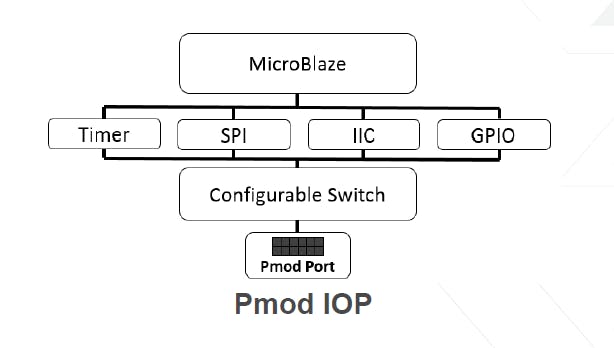
Concept Diagram
All of the IP needed to implement a IOP is provided within either the Xilinx IP or PYNQ IP library.
IOP Implementation in Vivado
To get started with the PYNQ image the first thing we needed to do is clone the PYNQ directory such that we can create the Vivado design and then later build the PYNQ Image.
We obtain the PYNQ framework from
git clone https://github.com/Xilinx/PYNQ.git
Once this is downloaded we can create the base application using the IP available within the /PYNQ/Boards/IP directory.
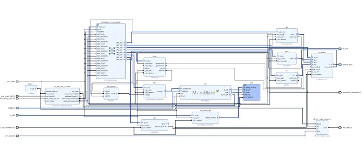
In this case the completed design for the Zybo Z7 board can be seen below and includes not only the IOPs but also GPIO for the buttons, switches, LEDS and three color LEDs.

Zybo Z7 Base PYNQ Design
A very important aspect of this solution is the use of the AXI interrupt controller to cascade the interrupts to the Zynq interrupt Generic Interrupt Controller.
Once the design has been completed we need to build the design in Vivado, and export the design so we can build a PetaLinux image.
Building PetaLinux
To build the PYNQ image we first need to create a PetaLinux BSP which means we need to create a new PetaLinux project and configure it for the hardware in Vivado.
If so far you created your Vivado design in Windows, to create both the PetaLinux image and the PYNQ image we need a Linux machine. To do these I use a Virtual Machine which uses Ubuntu 16.04 and has Petalinux and the PYNQ git repository downloaded on to it. If you are need a little more information on creating the build environmental check out this PYNQ Edition blog and Hackster Project
With the exported HDF from Vivado (Including the bitstream) available in the Linux build machine we need to run the following commands.
petalinux-create — type project — template zynq — name zybo
petalinux-config — get-hw-description Petalinux-build
Note once the hardware defintion is imported we will be presented with he PetaLinux project configuration dialog. As we do not need to make any changes then please just exit the dialog without saving anything. Building will take a few minutes.
Once the PetaLinux image is built the next step before we build the PYNQ image is to ensure the Linux image runs on the hardware. We can do this using the commands below
petalinux-boot –-jtag –-fpga
petalinux-boot –-jtag –-kernel
This will download the image to the Zybo board using the JTAG link and run up the image.
Once the boot is complete using a serial terminal we want to check that we can see the AXI GPIO in the LINUX device tree. From a command prompt we can run the command
dmesg
This will list the boot message and we can scroll through the message until we find the GPIO registration
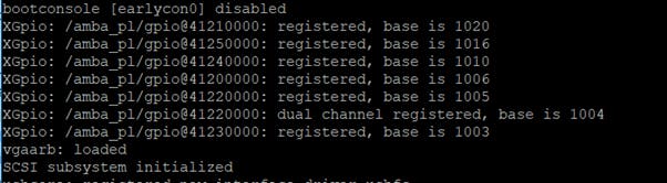
AXI GPIO Registration in PetaLinux
We can compare this against the memory map in Vivado and the addresses should be the same
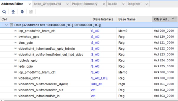
Vviado Memory Map
We can also connect to the Petalinux image over a network using SSH to ensure that interface is operational in the design. Once it is the next step is to prepare...
Read more »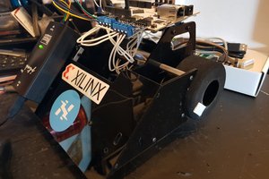
 EK
EK
 Chris
Chris