 Cees Meijer
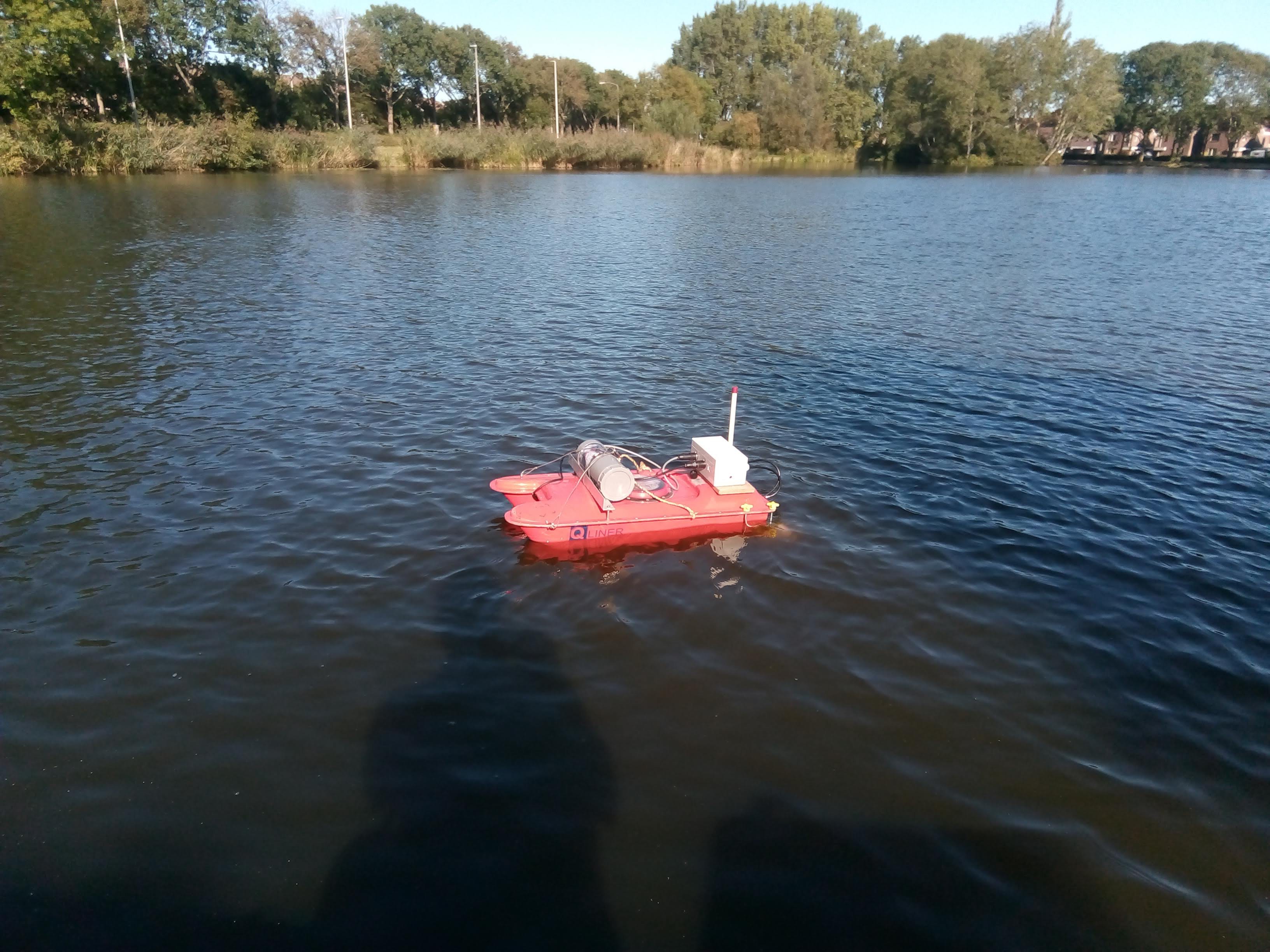
Around 2005 the company I work for (Nortek BV) introduced a system for measuring discharge on rivers: The Qliner. It is a little catamaran, equipped with a Doppler based current meter that could measure the flow in a river over the full depth. You had to keep it in position using ropes or a long stick.

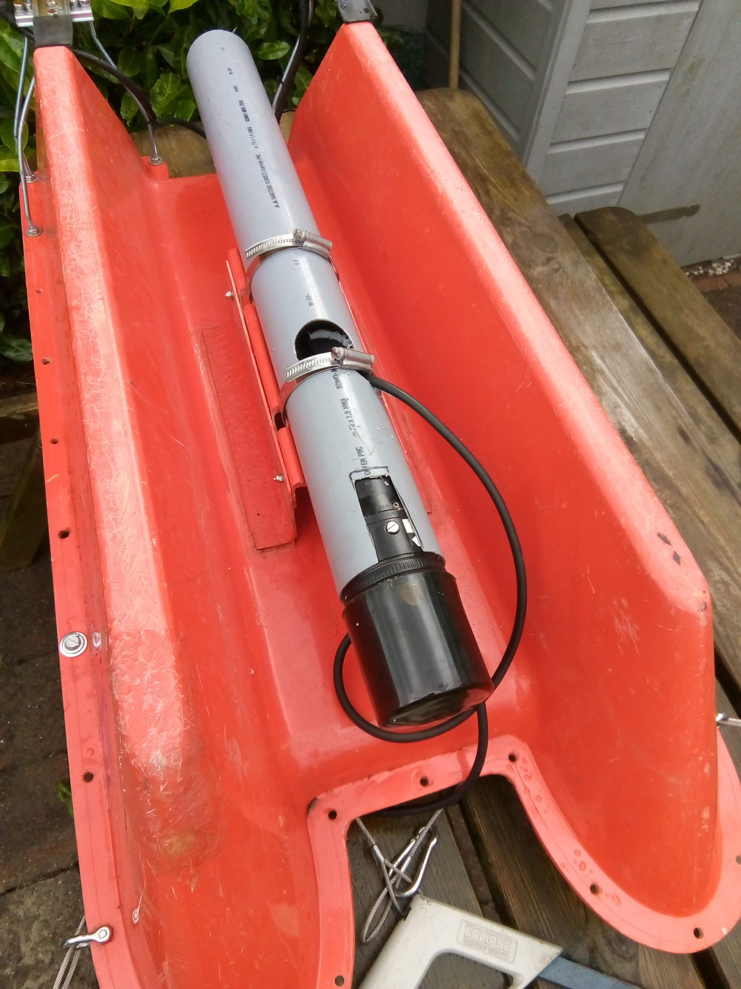
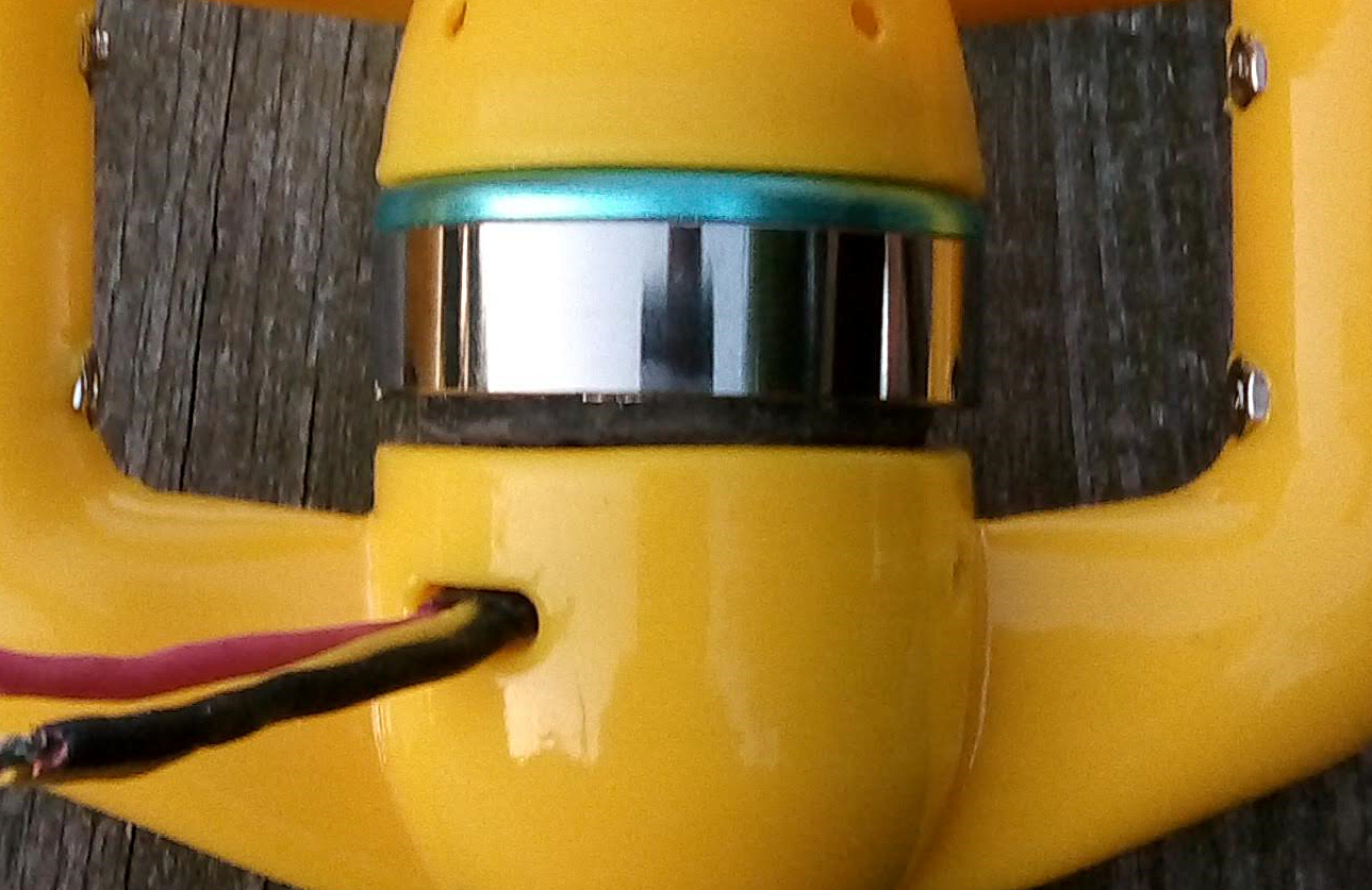
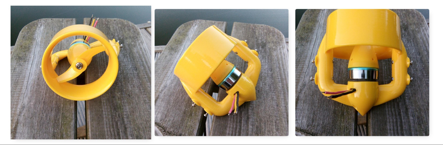
After a few years we sold the design to the German company OTT GmbH, who still manufacture it today. Meanwhile, we still have some of these catamarans that are no longer in use, and I always thought it would be nice to make one of these into a remote controlled boat. Then, a few weeks ago, I came across these low-cost thruster design: https://www.instructables.com/id/ROV-Thruster-105-Lbs-From-DT700-Brushless-Motor/ and decided that these were ideal for this project. So now I finally get started. The idea is to convert this boat to an a fully autonomous vehicle that can create a bathymetric map of a lake or river.
Think something like this: the Autonomous Surface Vessel (ASV), by Seafoor :
https://www.seafloorsystems.com/uau-usv
Or this one, by CHCNAV:
http://www.chcnav.com/index.php/product/pros?cid=1&ctype=5
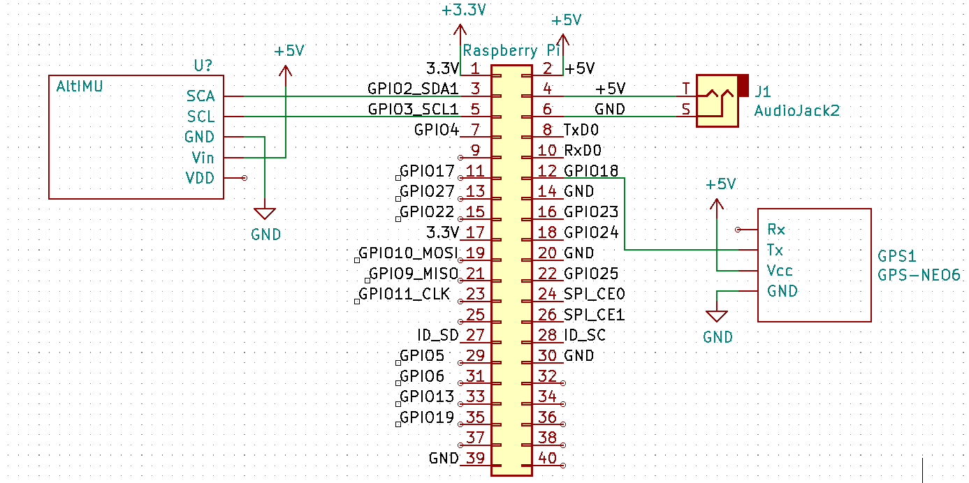
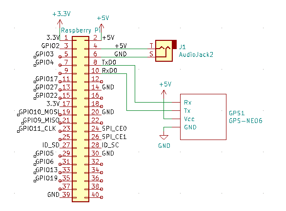
The boat will be driven by the two thrusters. An Arduino or Raspberry Pi will be used to control it, assisted by an electronic compass and GPS.
Though I first considered creating my own control software, it's probably not worth it since the ArduPilot project already has done a great job on this. And there is even a special 'Boat Configuration' section, so that makes it super simple to implement.
And, as always when you start looking into these things, it has been done before:
Ah, well, never mind. I'm going to do it anyway...


 Make sure the pigio library is linked in when compiling. In Code:Blocks this is done in 'Project->Build Options', tab 'Linker Settings', add it to the 'Link Libraries' list.
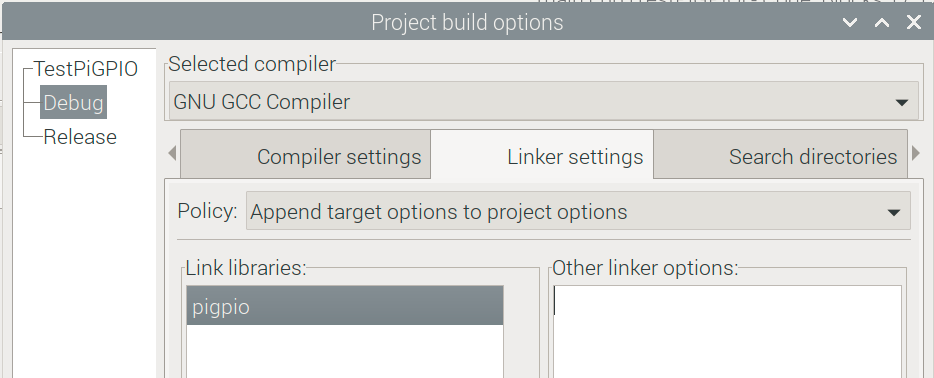
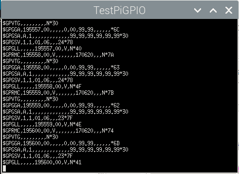
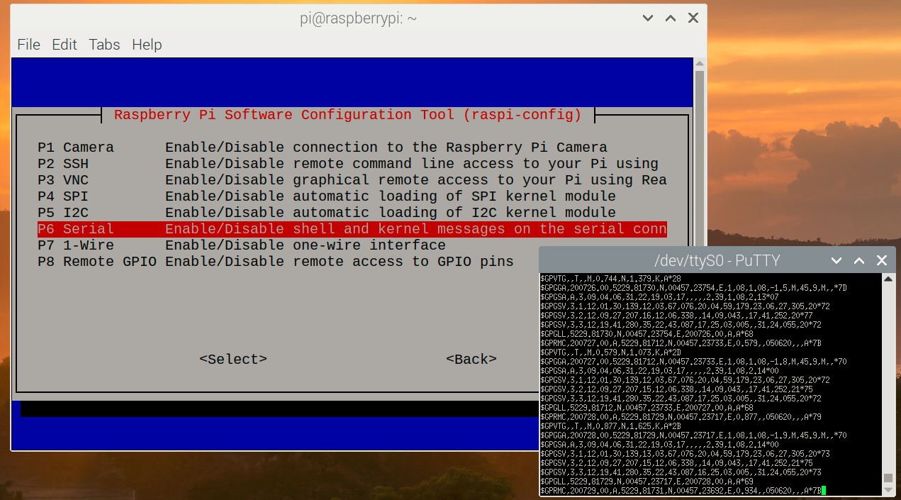 Now I installed PuTTY (sudo apt-get install putty), set it up for Serial port '/dev/ttyS0' and 9600 baud. This immediately shows the NMEA text messages as they are coming from the GPS receiver. Can't be easier than that.
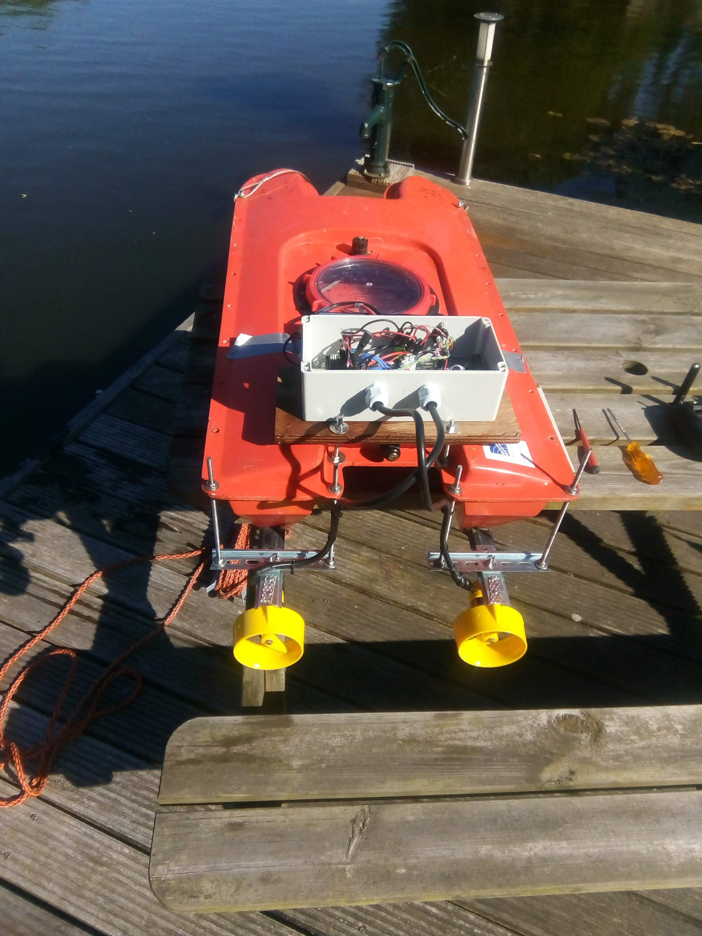
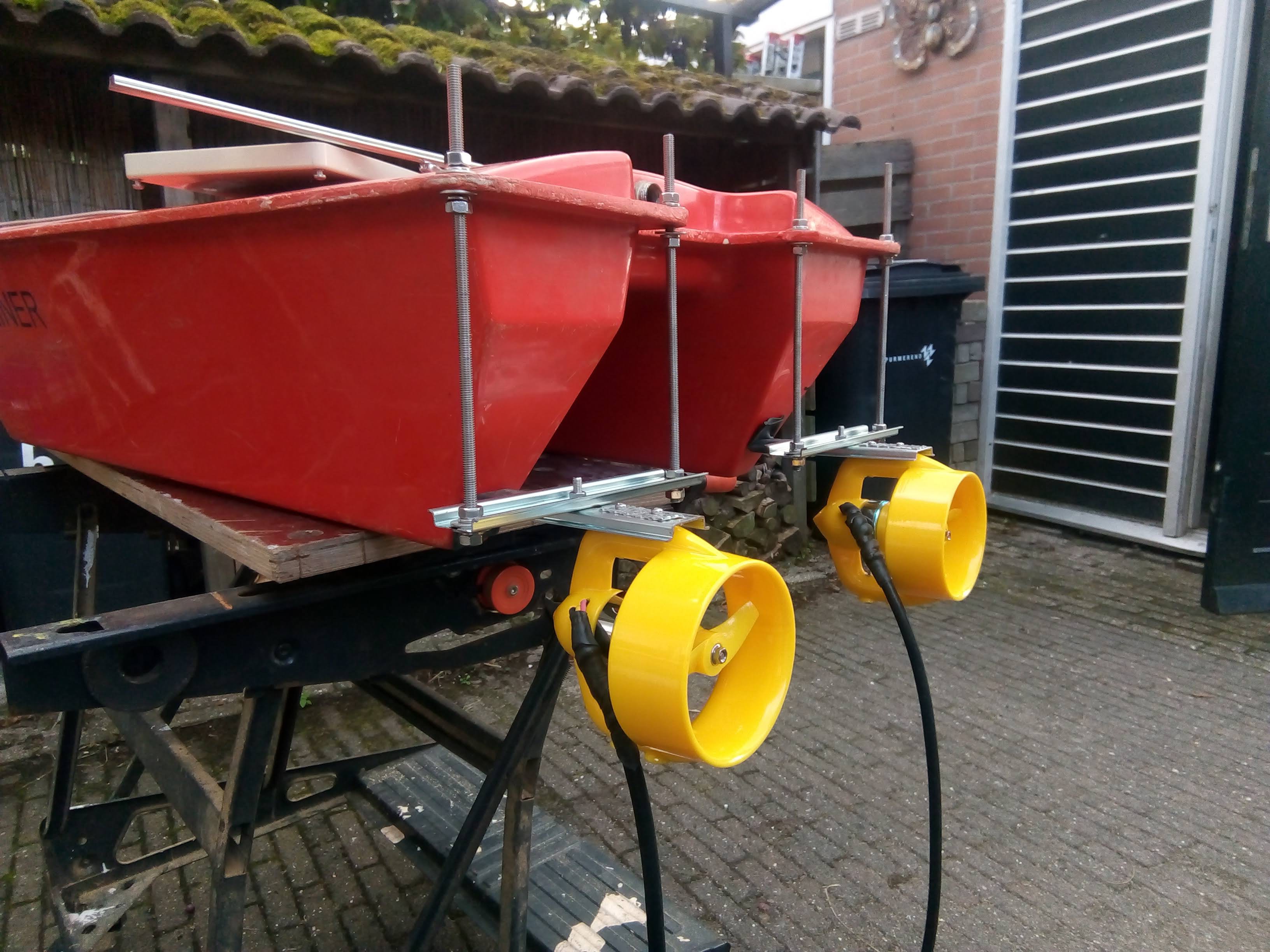
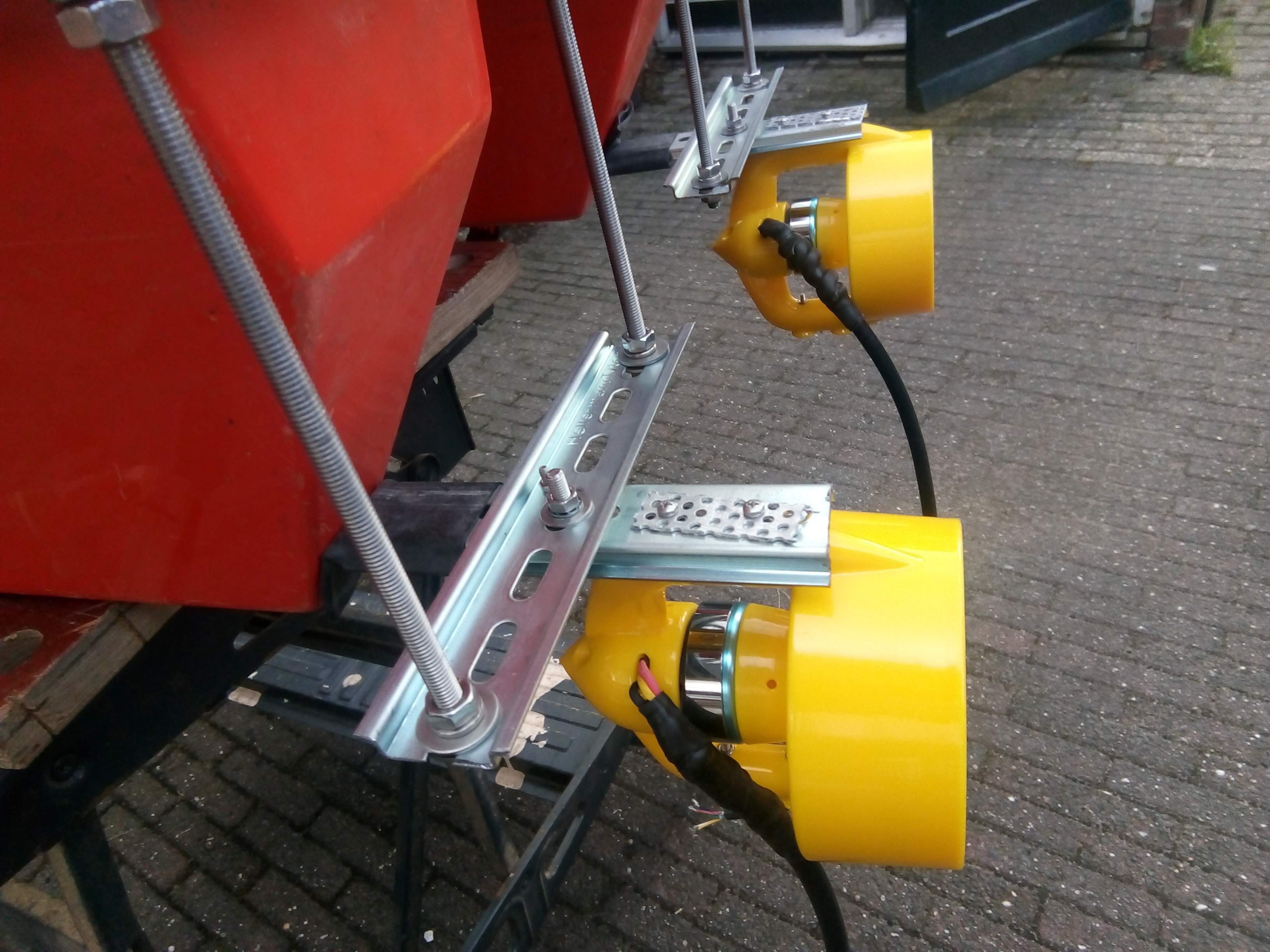
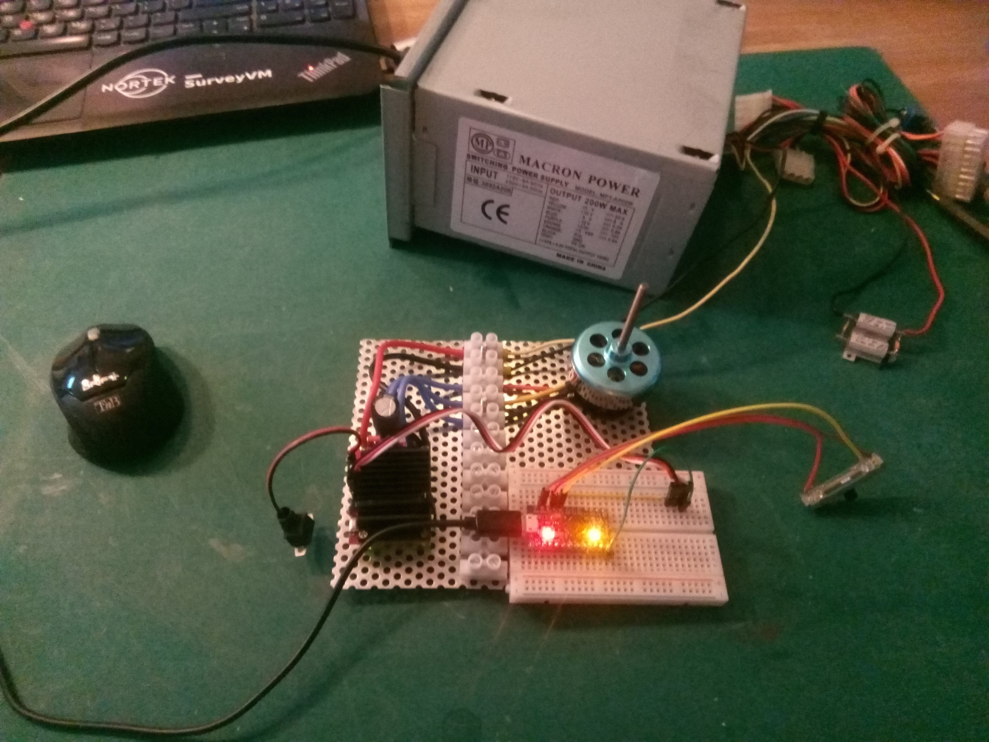


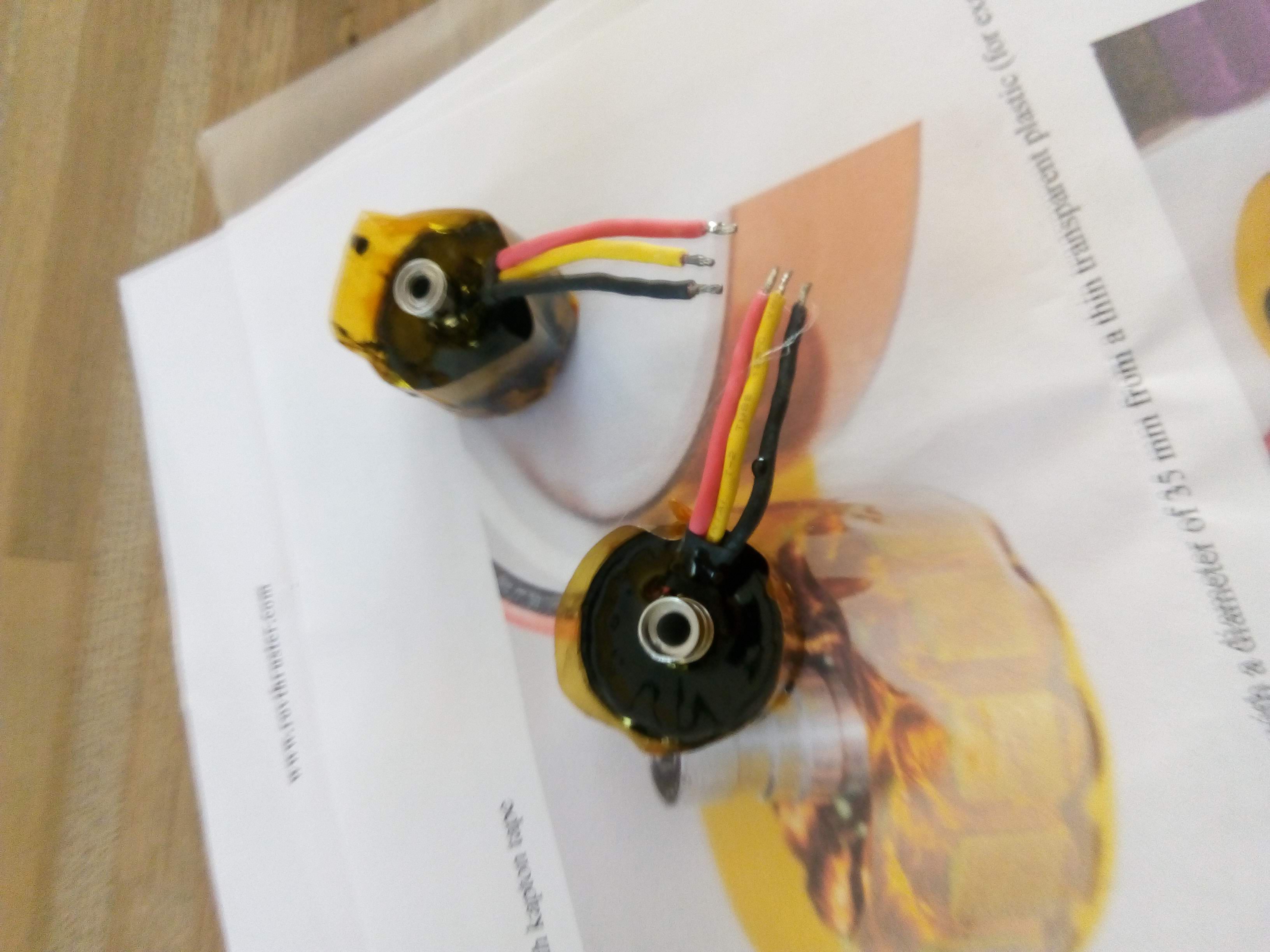
 So now I have two thrusters. In the mean time my
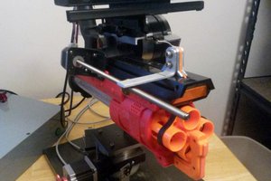
 Drew Pilcher
 Wassim
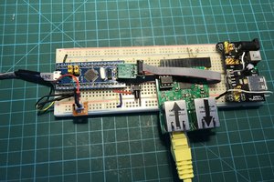
 ArsenioDev