 Ben Jacobs
Project Overview
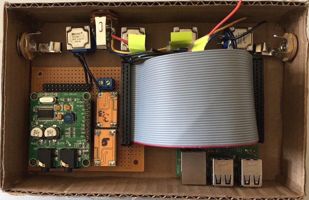
This project is comprised of five main subsystems, tied together by the main processor board, the Raspberry Pi 3B+.
The subsystems are as follows:
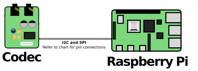
- The Audio Codec
- Provides Hi-Fi audio input and output for the Raspberry Pi
- Communicates over i2C and I2S/SPI
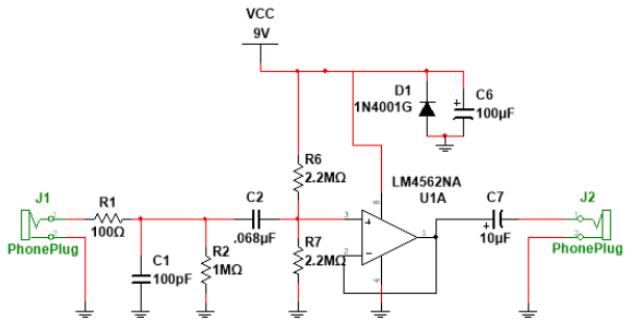
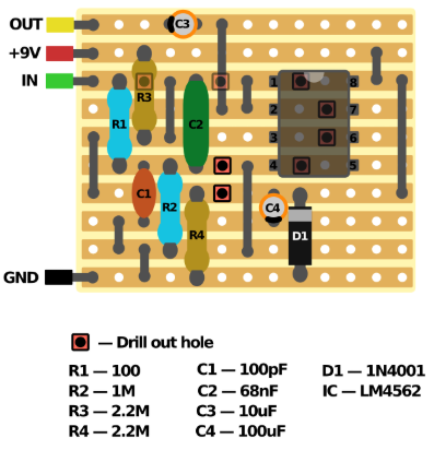
- The Preamplifier
- Impedance matches between guitar and Audio Codec
- Comprises of an operational amplifier (OPAMP) circuit in voltage follower configuration
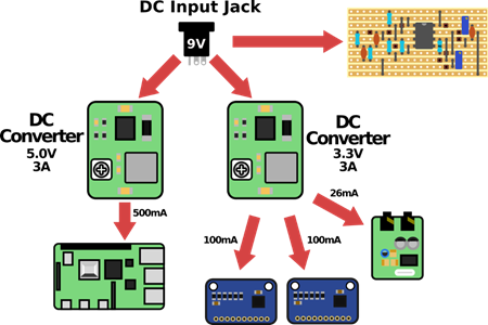
- The Power Supply
- Takes a DC 12v input
- Provides +5v and +3.3v outputs at 3A of current each
- Powers all other subsystems
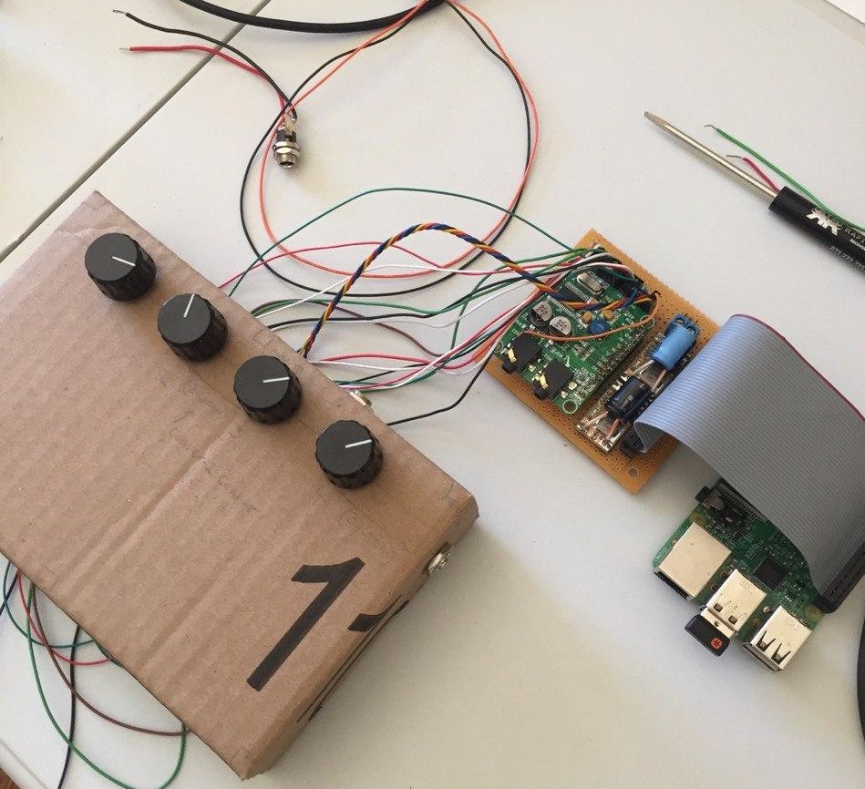
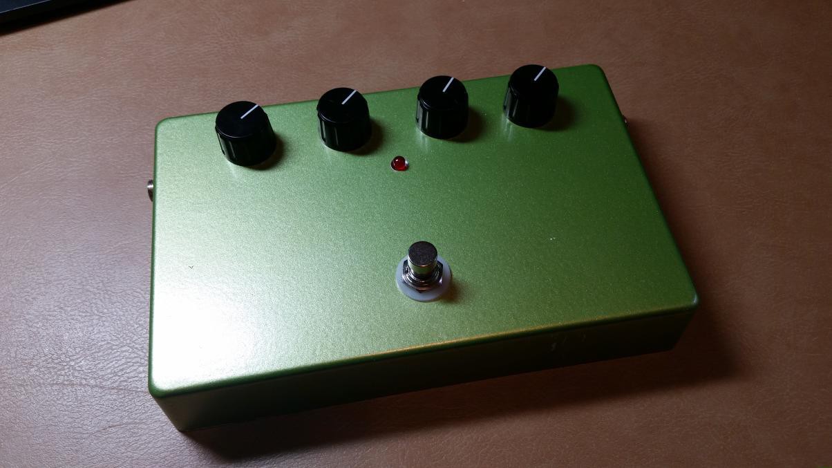
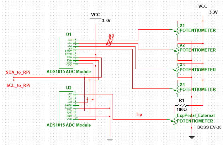
- The Human Interface
- Allows modification of effect parameters (such as boost, modulation amount, etc)
- Comprised of two ADS 1015 ADC boards, four potentiometers, and an expression pedal input
- Python script is required to take the ADC values and use them in the DSP
- The Mobile App
- GitHub page is here: https://github.com/kremerbe/GuitarPedalApp
- Provides the mobile interface for the hardware
- Written in React Native with support for Android and possibly Apple in the future
- Allows importing PureData effects you or someone else has created
- Keeps a list of effects you like on your phone for easy-access
- Allows effects saved in the app to be sent to the hardware utilizing Bluetooth
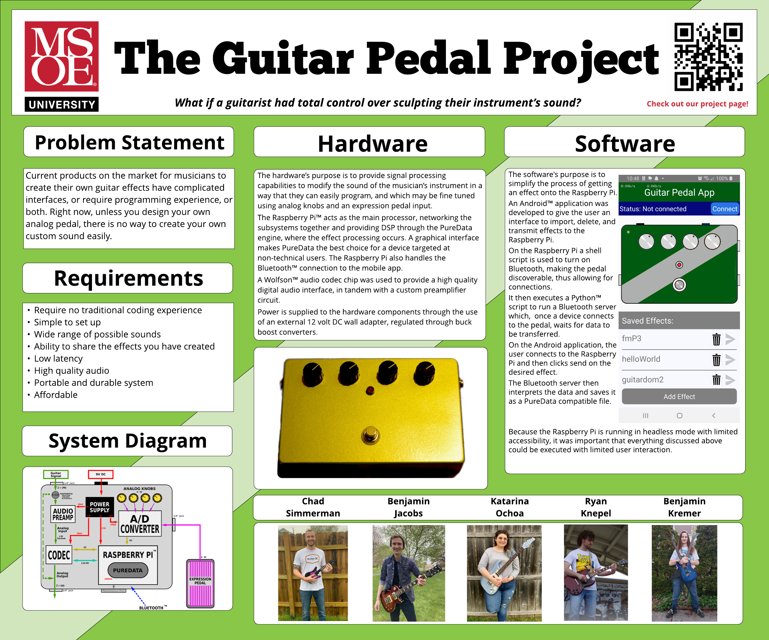
Design Project Poster
As part of Senior Design in the MSOE Colleges of Engineering, each team must make a large-format poster summarizing their work and accomplishments over the past year. Below is our poster, created by team member Katarina Ochoa.
 Xabi Z
 Aspiring Roboticist
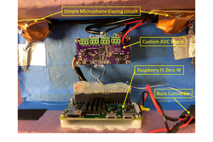
 Filip Mulier
 ssla-couk