-
The Nanodrone Pi Shield
08/15/2020 at 21:39 • 0 commentsTested and Working
After a number of tests and revisions – involving several software updates – the Raspberry Pi shield to control the on-fly operations (image capture, data processing, data transmission to the ground station) is stable and following the bench tests it works fine.
An important change I have done is the use of the original PiJuice HAT instead of the previously mentions UPS power supply. The reason is the difficult to receive the batteries for the power supply I initially considered to use (I am still waiting for the batteries delivery). Introducing the PiJuice HAT (all the software and hardware documentation can be found on the PiJuice GitHub repository) also got me the possibility to start the drone operations of the flying module easier and automatically.
The Shield Prototype
![]()
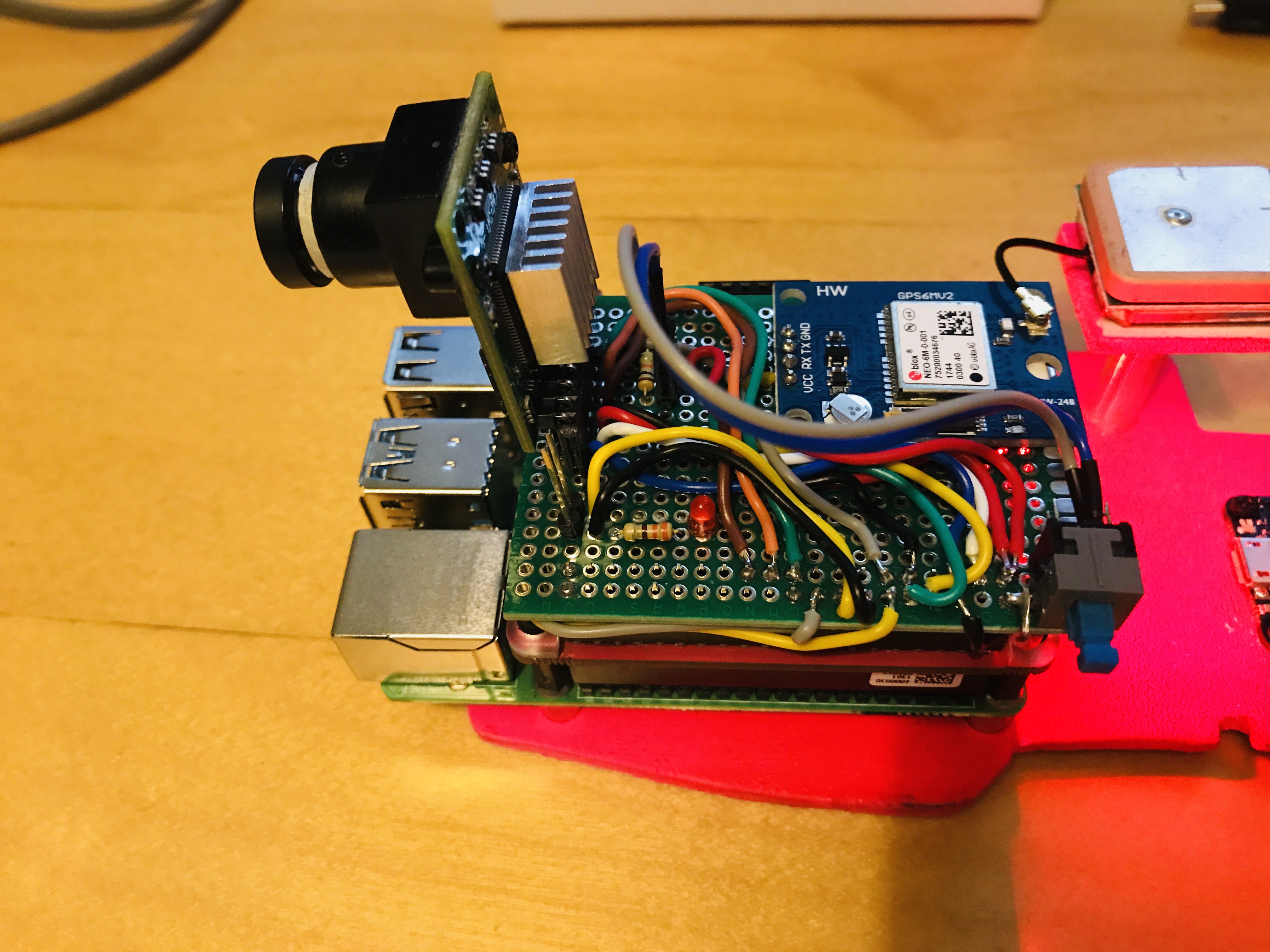
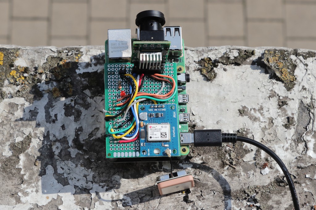
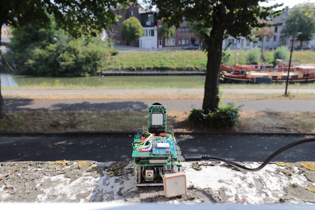
Above: the final version of the Raspberry Pi Nanodrone shield
The small board hosts the camera and the GPS but also includes a LED used to signal with different blinking sequences the current operation and a switch. When the program is running it remains in standby until the switch is not pressed. The application is launched by a bash shell script controlled by one of the two buttons of the PiJuice HAT (the Nanodrone shield is inserted on top).
A Simple PiJuice Configuration
![]()
![]()
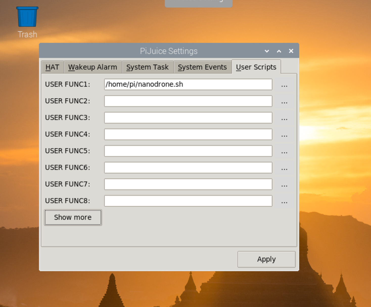
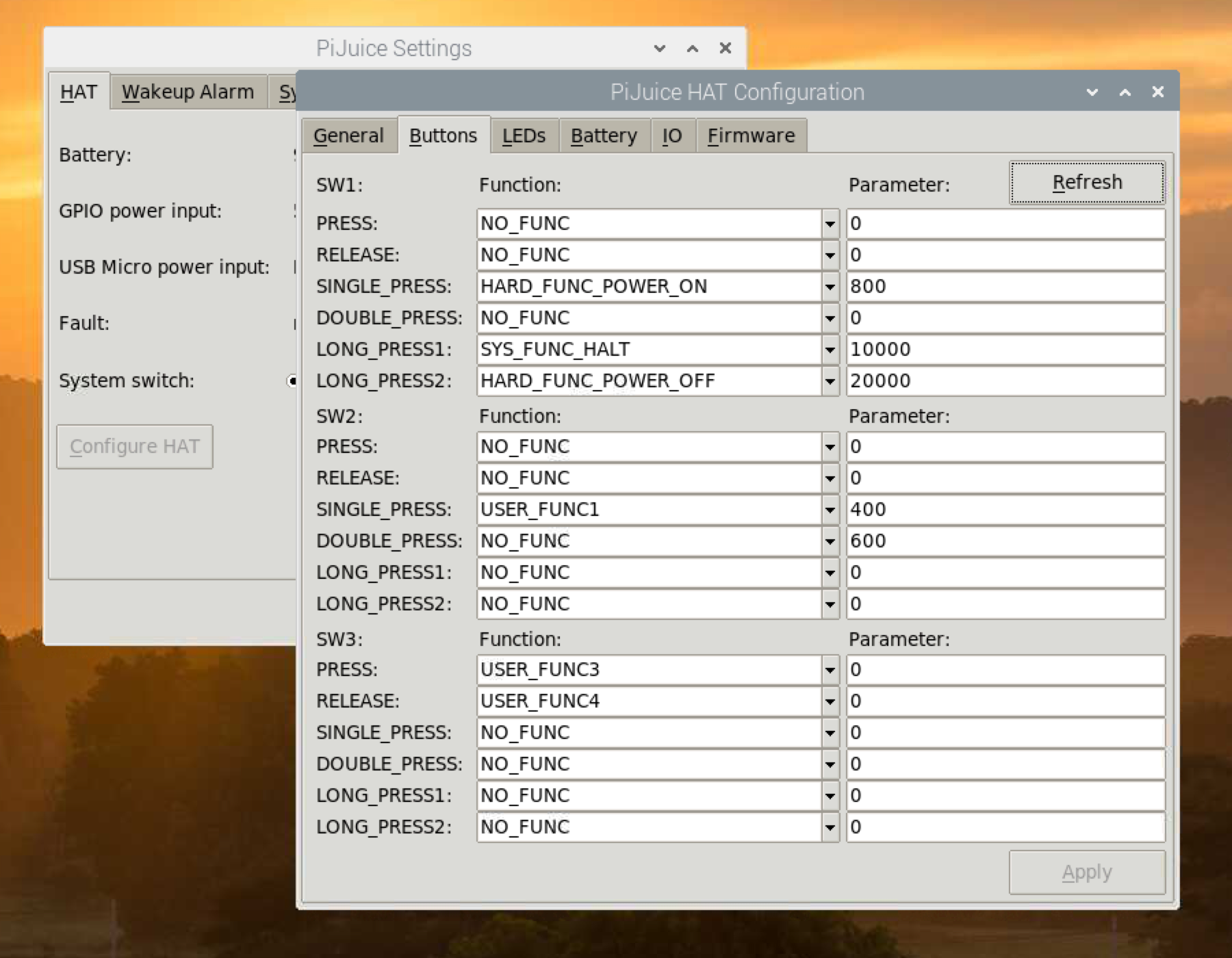
The two screenshot above shows the simple configuration of the PiJuice: on the left I defined the bash command to launch the Nanodrone application as User Function 1; on the right the User Function 1 is associated to the switch SW2 of the PiJuice board (the external one).
The Circuit
![]()
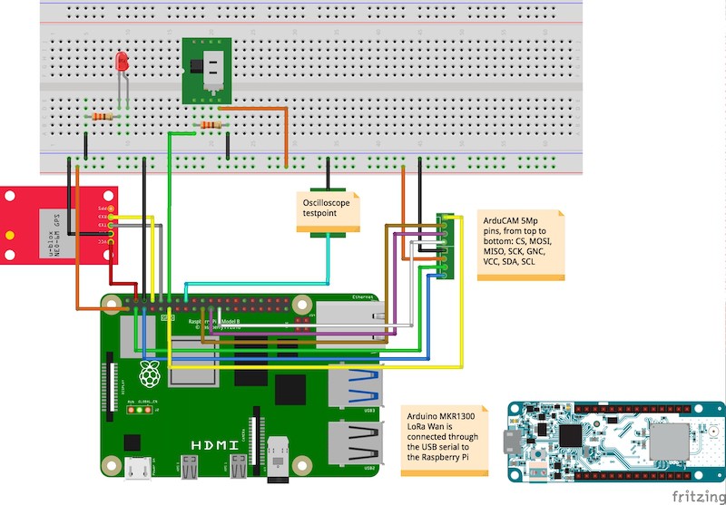
The above image shows the schematic of the circuit. In the definitive design I also kept the two testpoint pins for future performance tests.
The Software Logic
When the PiJuice user button SW2 is pressed the program is started. On startup the signal LED flash once 50ms just to sigal that everything is ok until this point. Then, all the time-consuming operations are executed during the startup phase: hardware checking, GPS initialization, camera initialization and setup (resolution, jpeg mode, etc.)
After the initialization completes, the LED start flashing 50ms every second; it is the signal that the program is running and checking continuously if the switch has been set to on. The system is ready to fly.
When the switch is set to the on position the LED start flashing for 18 second at different frequencies: it is a countdown to give to the user to start the drone and move it in the initial position. When the countdown finishes, it is acquired the first image.
The acquisition process continue until the switch is not set to the off position; it is expected to be done when the drone lands. This logic is implemented in the first program for test fly firstfly available in the GitHun Nanodrone repository.
-
The SerialGPS Class
08/13/2020 at 12:32 • 0 commentsIntroducing the SerialGPS Class
The GPS device continuously stream data through the /dev/ttyS0 port of the Raspberry Pi – the serial connection available on the pins number 8 (Tx) and 10 (Rx) corresponding respectively to the BCM pins 14 and 15 and the pins 15 and 16 of the Wiring Pi library.
After the serial interface has been set up correctly in the Linux system, indeed, we don't need to configure further any hardware control. We should only consider this information in order to avoid using these pins but connecting them to the Rx and Tx pins, respectively of the GPS receiver board. The whole management of the GPS data is covered by the SerialGPS class through APIs specific the application.
When the class is instantiated by the application we should only pass the right /dev/tty* name of the Linux serial device.
To get the current GPS coordinates the getLocation() API retrieves a data buffer from the serial, parse it and return a pointer to a GPSLocation structure with the data we need (see the structure content below).
//! Defines a GPS location in decimal representation
struct GPSLocation {
    //! Latitude
    double latitude;
    //! Longitude
    double longitude;
    //! Speed
    double speed;
    //! Altitude on the sea level
    double altitude;
    //! Direction
    double course;
    //! Signal quality index 0 - n
    uint8_t quality;
    //! Current number of satellites
    uint8_t satellites;
};
Note: for the Nanodrone project we only need to know the decimal coordinates for longitude and latitude-– the same numeric representation adopted by default by Google maps – and information on the number of detected satellites (fix) and signal quality.
As a matter of fact, the only two NMEA messages the class consider and pause are $GPGGA and $GPRMC. Without much effort the class can be upgraded for decoding more NMEA sentences in order to define a more detailed scenario of the GPS status.
Special Methods in the SerialGPS Class
In addition to the GPS data APIs I have also added' the method getTargetDistance(). Passing a coordinate pair to this method we get the distance in meters of this target from the last known position.
-
Hardware On-the-fly
08/12/2020 at 19:59 • 0 commentsThe Flying Platform
Hardware
The first part of the project consists of the creation of a simple Raspberry Pi shield supporting the camera and the GPS on a single board plugged into the Raspberry Pi GPIO 40 pins connector.
Adopting this solution makes the whole device as much compact as possible for stability when fixed on the drone, as well as reducing as much as possible the weight due to the relatively limited payload of the drone (between 900 grams max).
These devices consume, respectively, the Raspberry Pi serial interface /dev/ttyS0 (the GPS module) and the I2C(1) and SPI(0) ports to interface the camera. To make the camera working efficiently I have developed a camera driver class derived by the original Arducam for Arduino (originally developed in C with a lot of issues and redundant, time-consuming functions) where the most important changes are the conversion to a general-purpose (for the Pi only) C++ class, together with consistent improvements and revisions.
Note: all the software updates, as well as the related materials like the STL files and designs are constantly updated on the Nanodrone repository.
Camera: Usage and Performances
For testing the software along the development process, as well as verifying that the hardware complains to the expectations, I have developed a terminal, interactive testlens application to test the features and performances of the hardware and the processing algorithms. To verify precisely the performances a GPIO pin has been used as test-point; the below snippet shows the function called before and after the process under testing for time-compliance.
void debugOsc(bool state) {
    digitalWrite(DEBUG_PIN, state);
}
The DEBUG_PIN status (set to true when the desired process starts and false when the process ends) timing is checked with an oscilloscope to verify the precise time duration of the process.
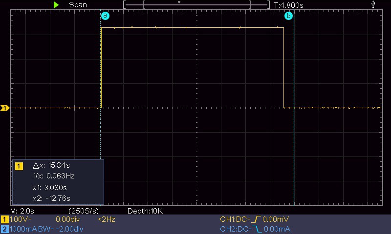
![]()
The above image, for example, shows the duration of the camera initialisation; due to the long time required to initialise the device it is done once before the acquisition sequence and the camera remains open for images capture until the acquisition session is not ended.
The timing performances with the Arducam controlled by a Raspberry Pi 4 is the following (using the ArduCAM class developed for this project):
- Camera initialisation: about 15.5 sec
- Image acquisition: from 20 ms (320x240) up to 1.5 sec (full resolution, 5 Mp)
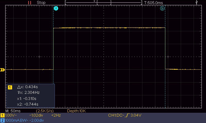
The acquired image is never send outside of the Raspberry Pi (the flying module) but it is processed with a series of proprietary algorithms using the features of the OpenCV library to convert the images in multi dimensional arrays. The screenshot below for example shows the duration of 505 ms for the image equalisation and optimisation algorithm called automatically after every capture.
![]()
As the whole system should work real-time it is strategical the speed at which the captured images can be processed to extract the key information collected by the ground station. The image processing is applied to the captured images by specific APIs I am developing in the ImageProcessor class. Based on the tests done with the different capture resolutions the optimal image size for processing in a reasonable time (about 1 sec.) is 1600x1200.
Camera: the Lenses
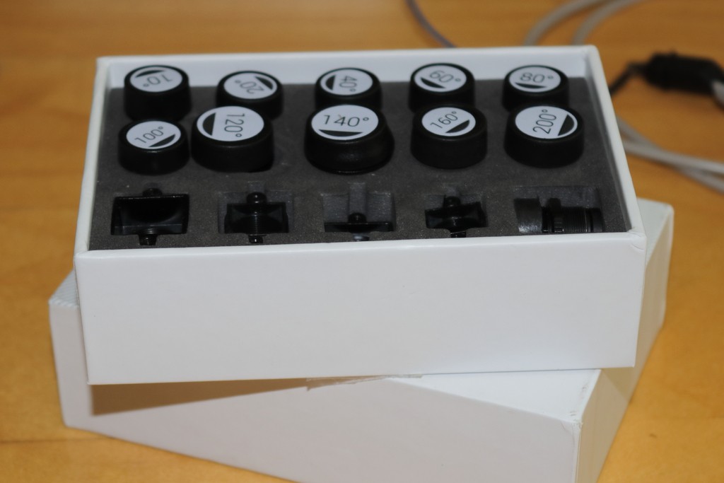
To be able to work in different visual scenarios, for example large fields, cultivation plants, small areas of terrain, ecc. I have acquired a series of different lenses for the camera and made some acquisition tests.
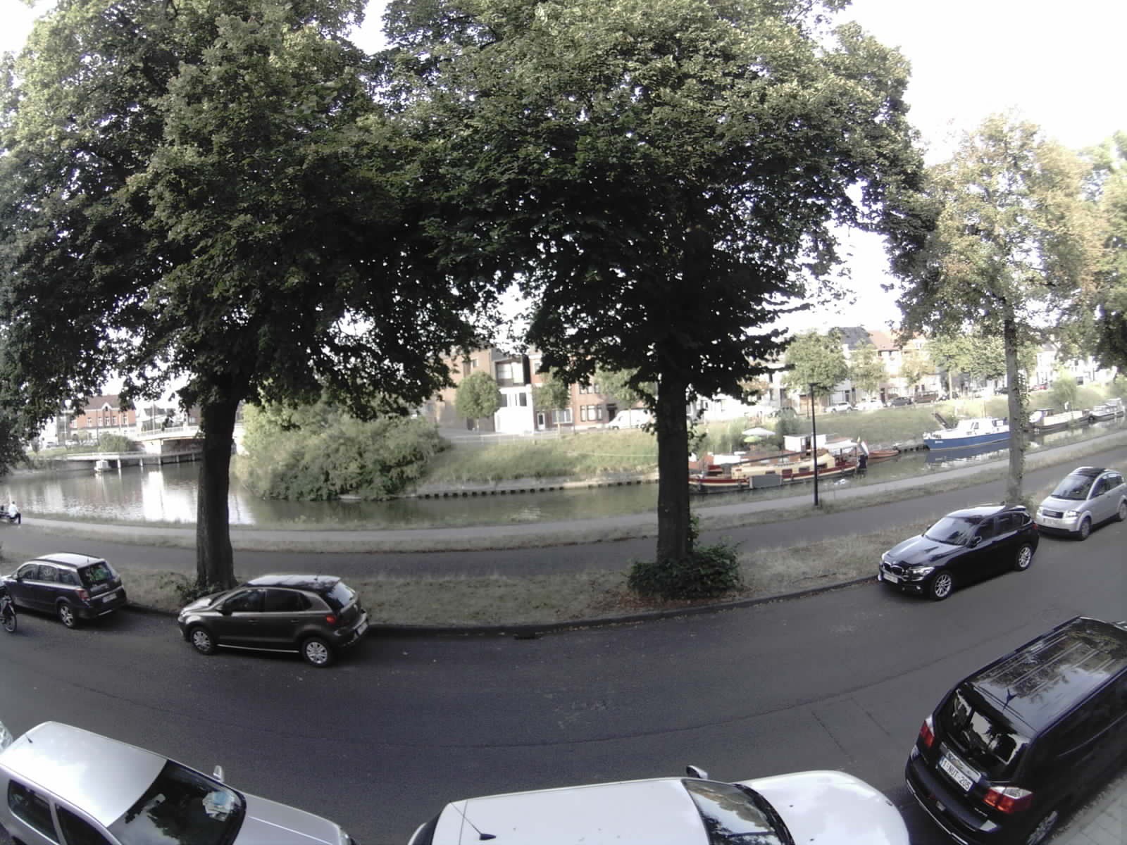
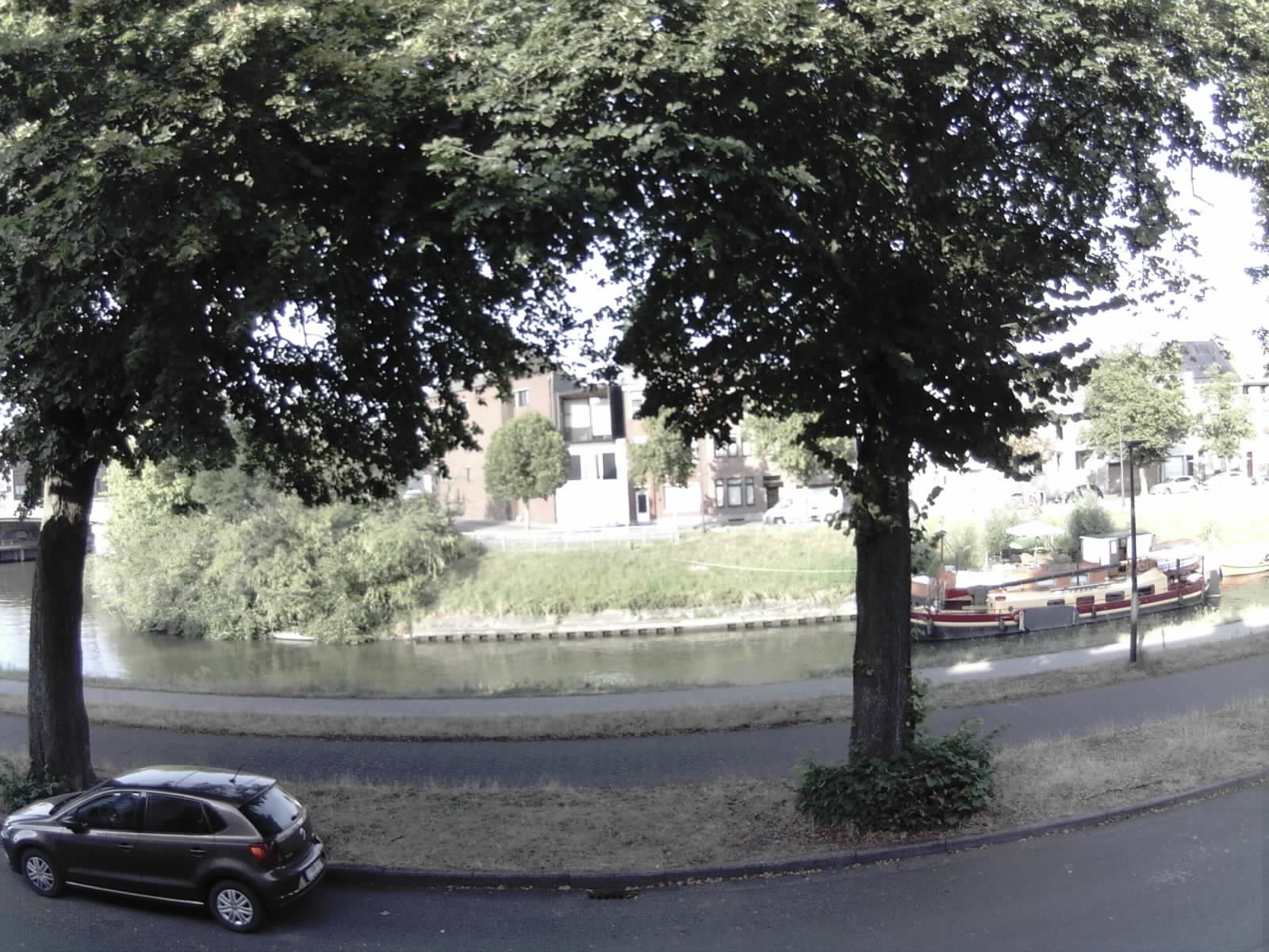
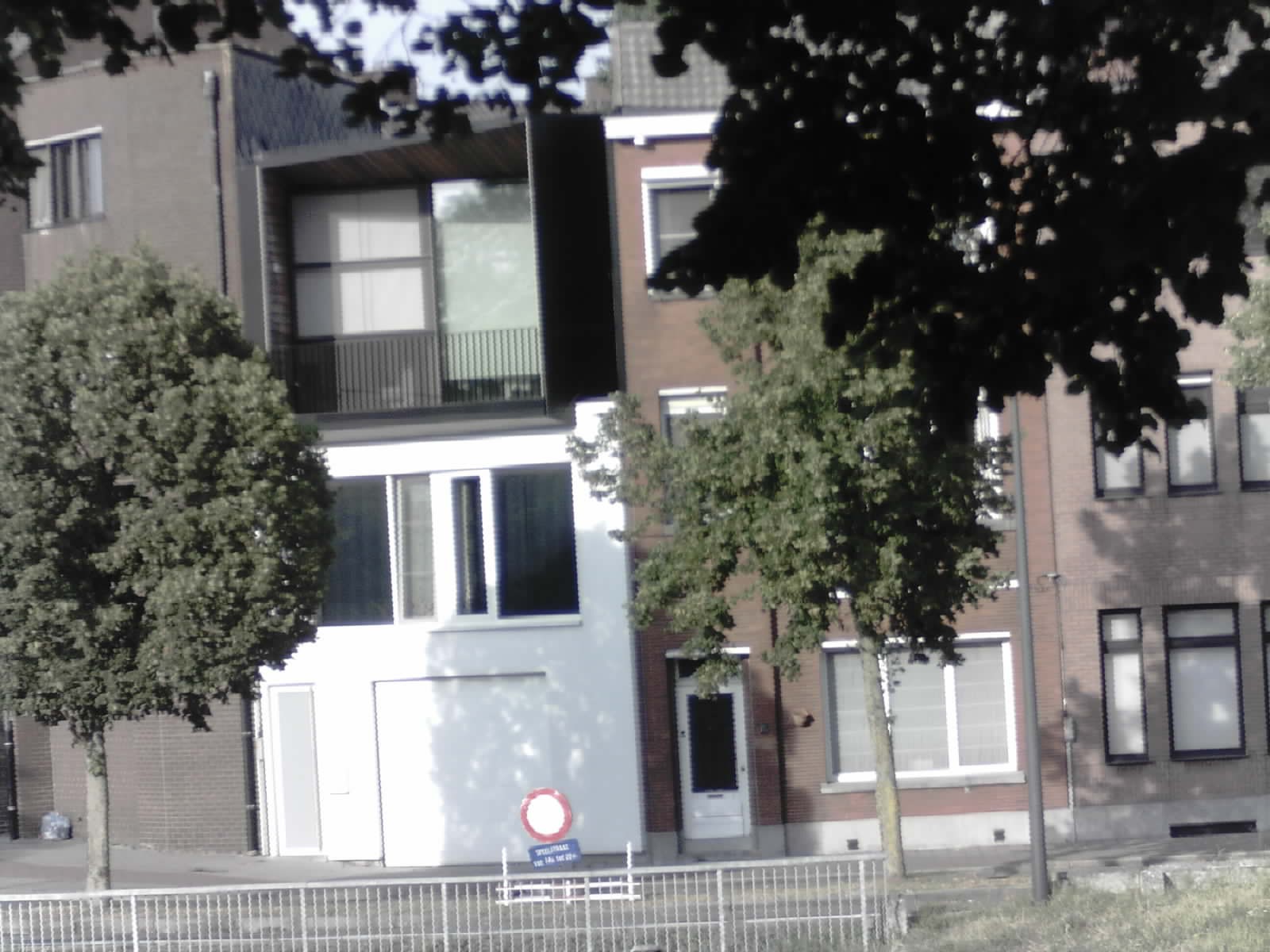
Above: the 10 lens set from an aperture of 10 Deg (telephoto) up to 200 Deg (ultra-wide angle)
Above: Indeed, the lens test images have been all acquired from the same point of view to have a comparison reference.
The images below shows some examples of different kind of lenses capturing the same scenario
![Wide angle Wide angle]()
![]()
![]()
-
Experiment #1: Targets Along a Path
06/09/2020 at 23:37 • 0 commentsThe video below shows the first experiment of creating a path that can be repeated by the drone with a series of targets, ideally representing the POI. The drone take a shoot every target point while the PSoC6 should collect data that will be integrated with the image analysis.
-
PSoC6 WiFi BT Pioneer Kit 3D Case Design
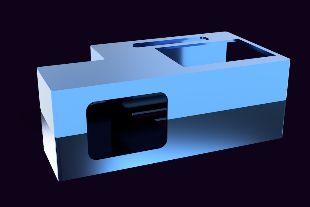
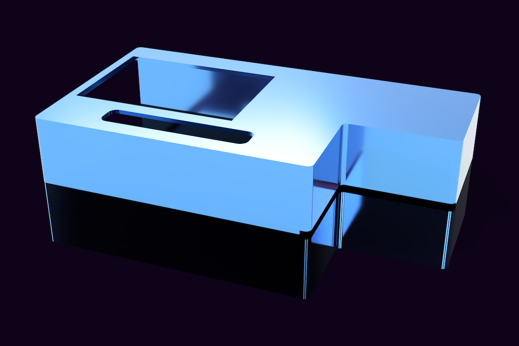
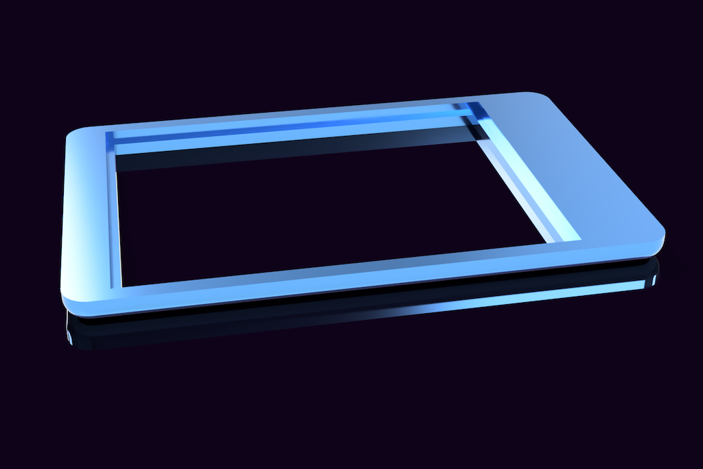
06/04/2020 at 18:35 • 2 commentsRendering of the images of the case, designed with Fusion360 and 3D printed with Elegoo Saturn 4K LCD 3D printer
![]()
![]()
![]()
-
Fields of Application
06/03/2020 at 20:46 • 0 commentsAdded the field of application (agricultural small and medium areas) as the environment where the first experiments of the prototype will be conducted. Added other kind of application that only need software customization.
-
Project Evolution
06/02/2020 at 12:14 • 0 commentsStage 1 - Project Details
In this first phase I define the project characteristics and features, components and the development workflow
Nanodrone For IoT Environmental Data Collection
A "Nanodrone" for environmental data collection and a Ground Control PSoC6 to interface the data to the cloud.
 Enrico Miglino