 Enrico Miglino
Introduction
The project idea is making a relatively low-cost system to monitor plants and cultivation areas to detect the grown state as well as potential parasite and damaged plants.
The device can be easily installed on a semi-autonomous UAV to cover large areas of terrain, as well as installed on a ground robotised device. The use of a UAV represents the most flexible solution compared to the ground mobile unit.
Some of the most challenging issues if adopting the ground mobile solution:
- Difficulty to move on the non-regular terrain
- Limitations due to the kind of plants
- Slower and more difficult mobility
- Reduced field of operation
- Slower back-to-home maneuvres
The video below shows the first fly of the flying prototype acquiring and pre-processing images real-time, installed on a Dji Mavic 2 Pro drone. The flying unit has a weight of about 250 gr (including batteries) while the payload of the drone is about 1 Kg.
This project is co-sponsored by Elegoo for the 3D printers and printing material.
Making the Prototype
The Nanodrone prototype is divided in two parts: a flying moduyle that will be installed on the Dij Mavic 2 Pro drone used in this project and a ground module that receives real-time the data from the drone and send them to the AWS IoT cloud, based on the PSoC6 Pioneer Kit.
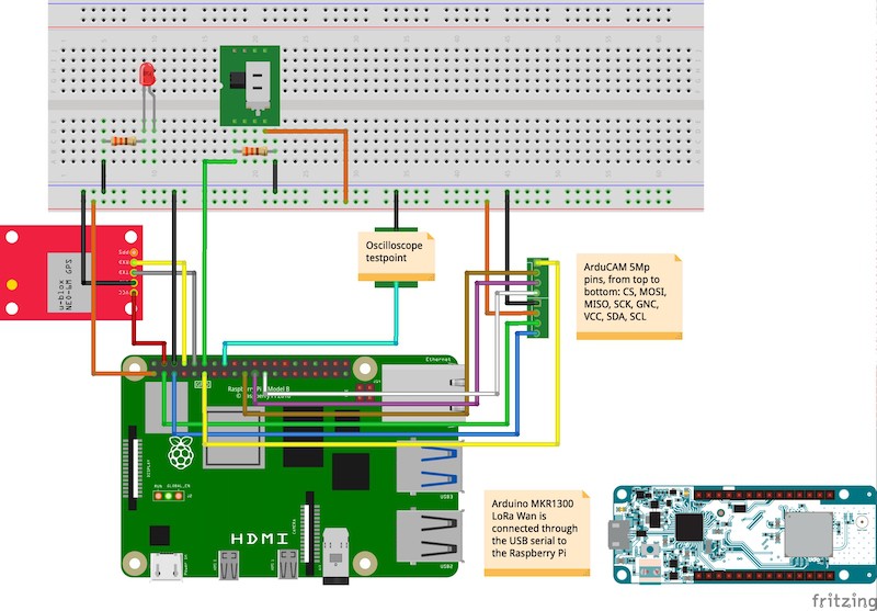
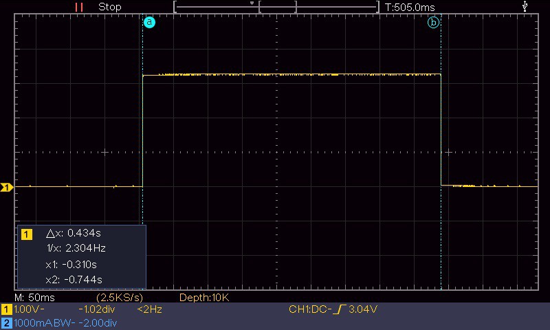
The two modules are connected via a couple of Arduino MKR1300 LoRa Wan linked peer-to-peer. I have decided to adopt the LoRa protocol for the communication to support a wider range of operation. With about 30 minutes of flying autonomy the drone can collect image data from large areas, process them in real-time and send a feed to the ground module. The LoRa protocol makes possible to keep a stable connection at a considerable distance: the expected covered area can be up to 1.000 square meters.
Flying Module
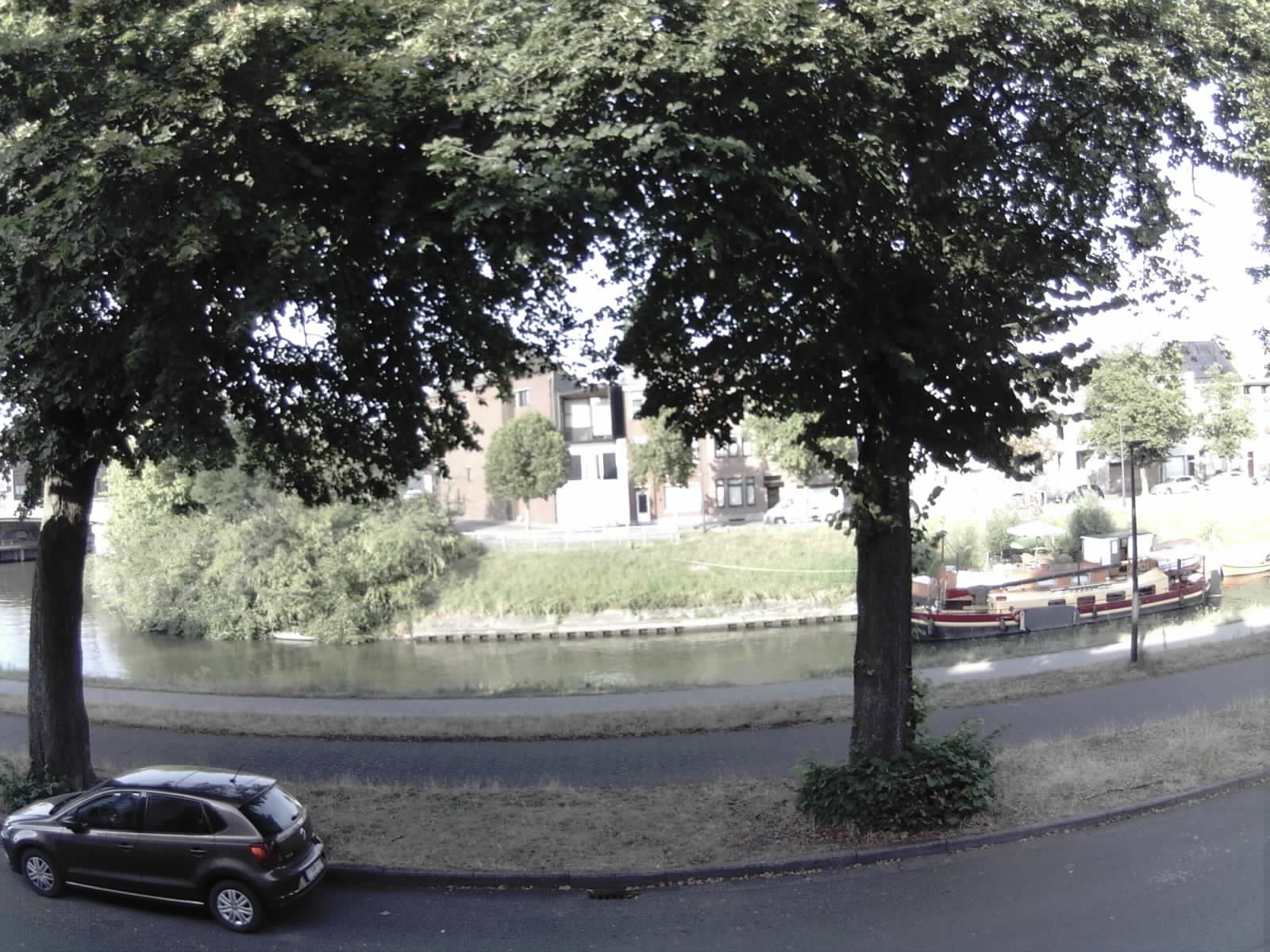
- A drone with onboard the collection/inspection device will move along a field following a predefined path.
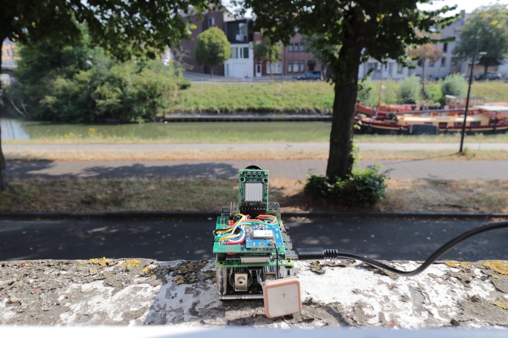
- The collected information – including visual data – coming from several sensors are integrated realtime and saved locally on a microSD card.
- The device has a GPS to save the acquisition points, independent by the drone navigation system
- The information are updated real-time from the flying unit installed on the drone, sent to the PSoC6 of the ground station using a LoRa connection by two Arduino MKR1300 LoRa Wan.The inspection set of retrieved data are sent to the AWS IoT Console via MQTT by the PSoC6 Pioneer Kit ground station integrated with the sensors of the PSoC6 device.
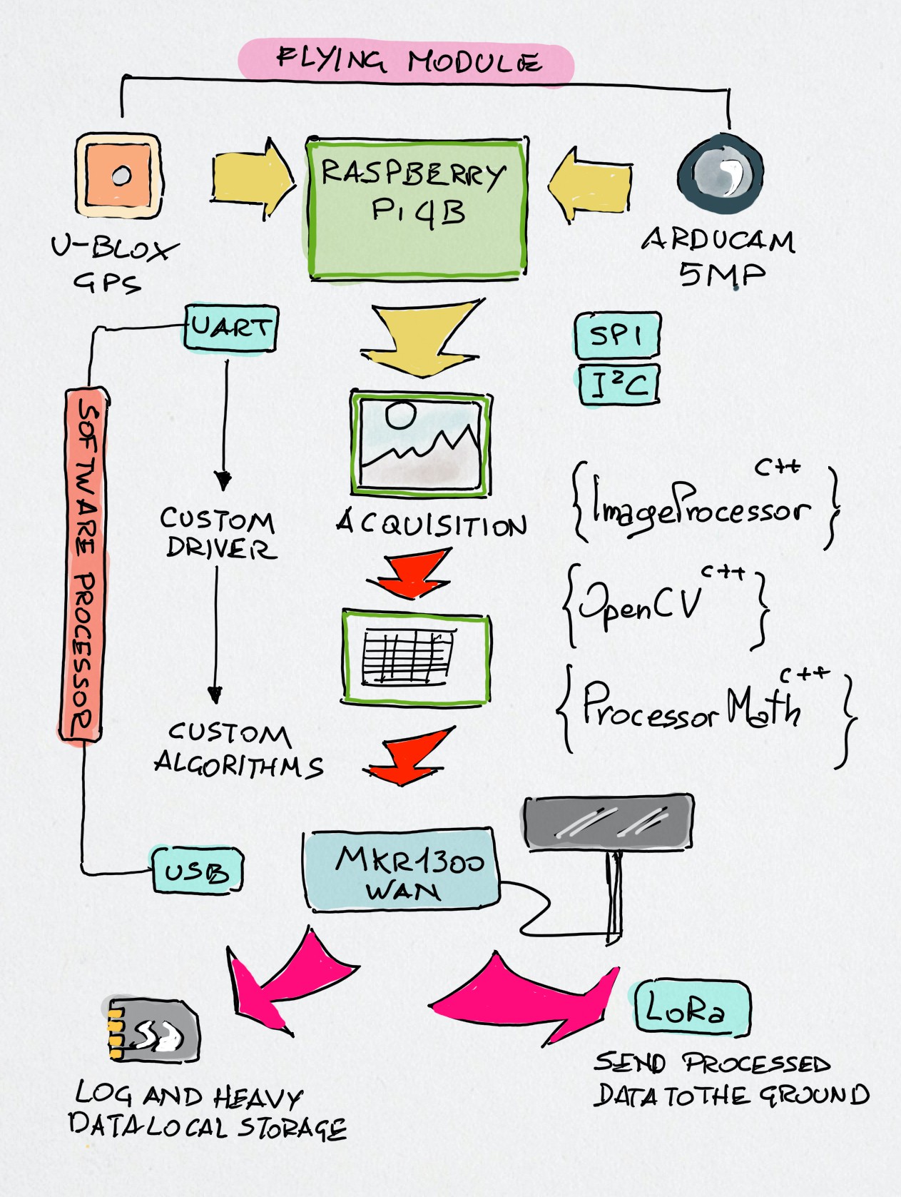
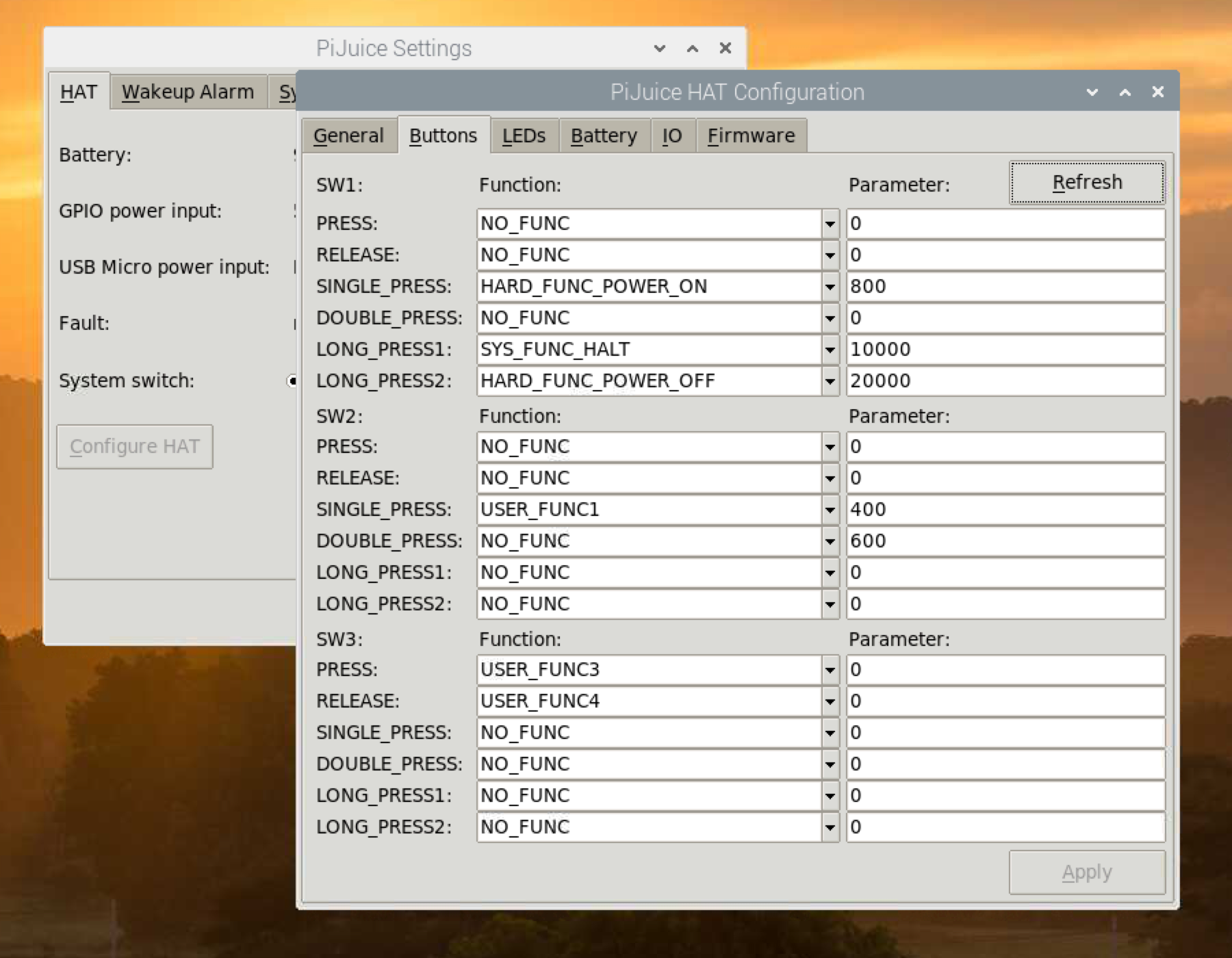
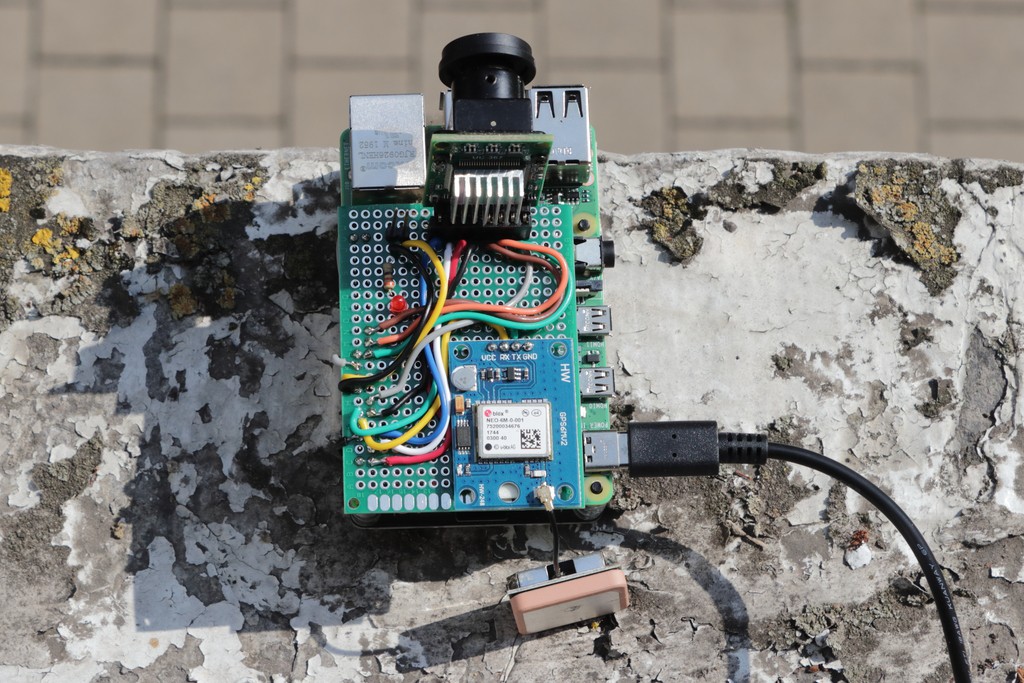
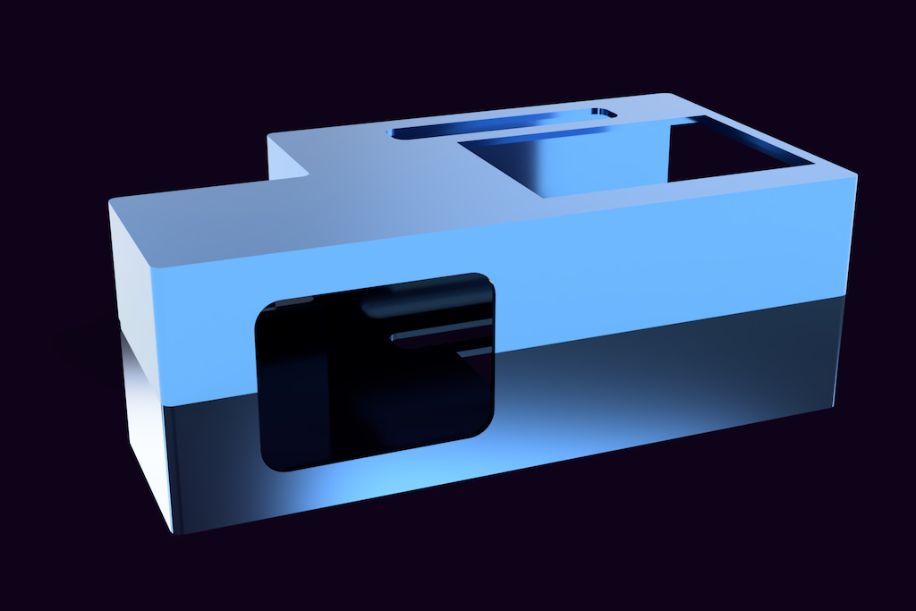
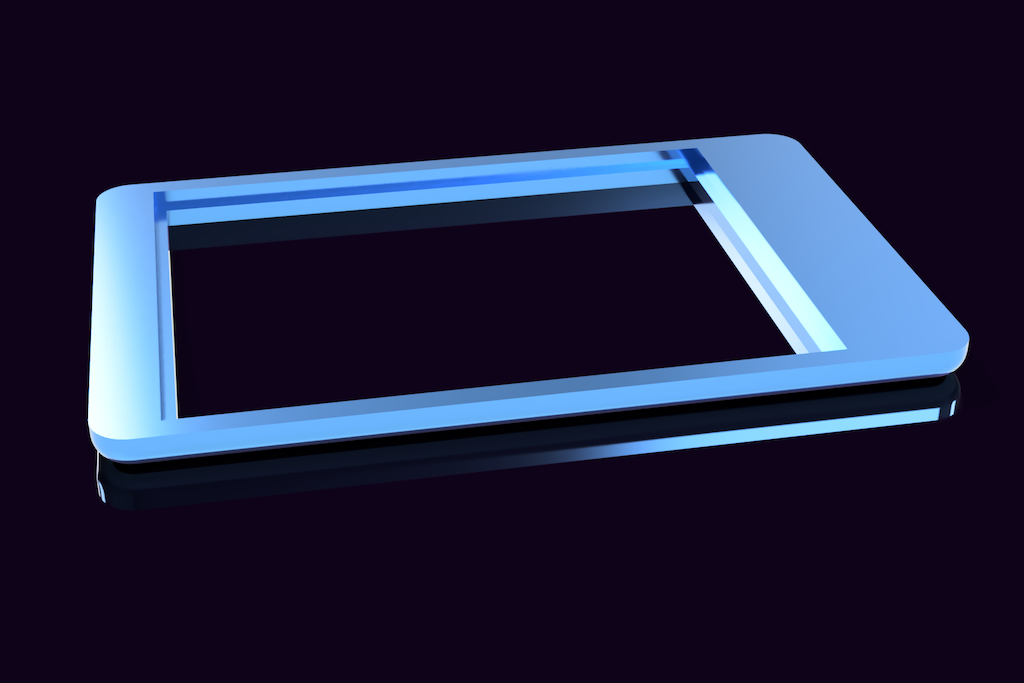
More details on the software and the Raspberry Pi custom shield in the log notes.
Ground Module
The Ground Module is based on the Cypress PSoC6 Pioneer Kit connected to the WiFi and to an Arduino MKR1300 LoRa Wan acting as the receiver. Having already developed on the PSoC6 both the WiFi Connection and the AWS IoT cloud data interfacing through the MQTT protocol, I have not considered the difficulty to connect it to the Arduino via the UART port.
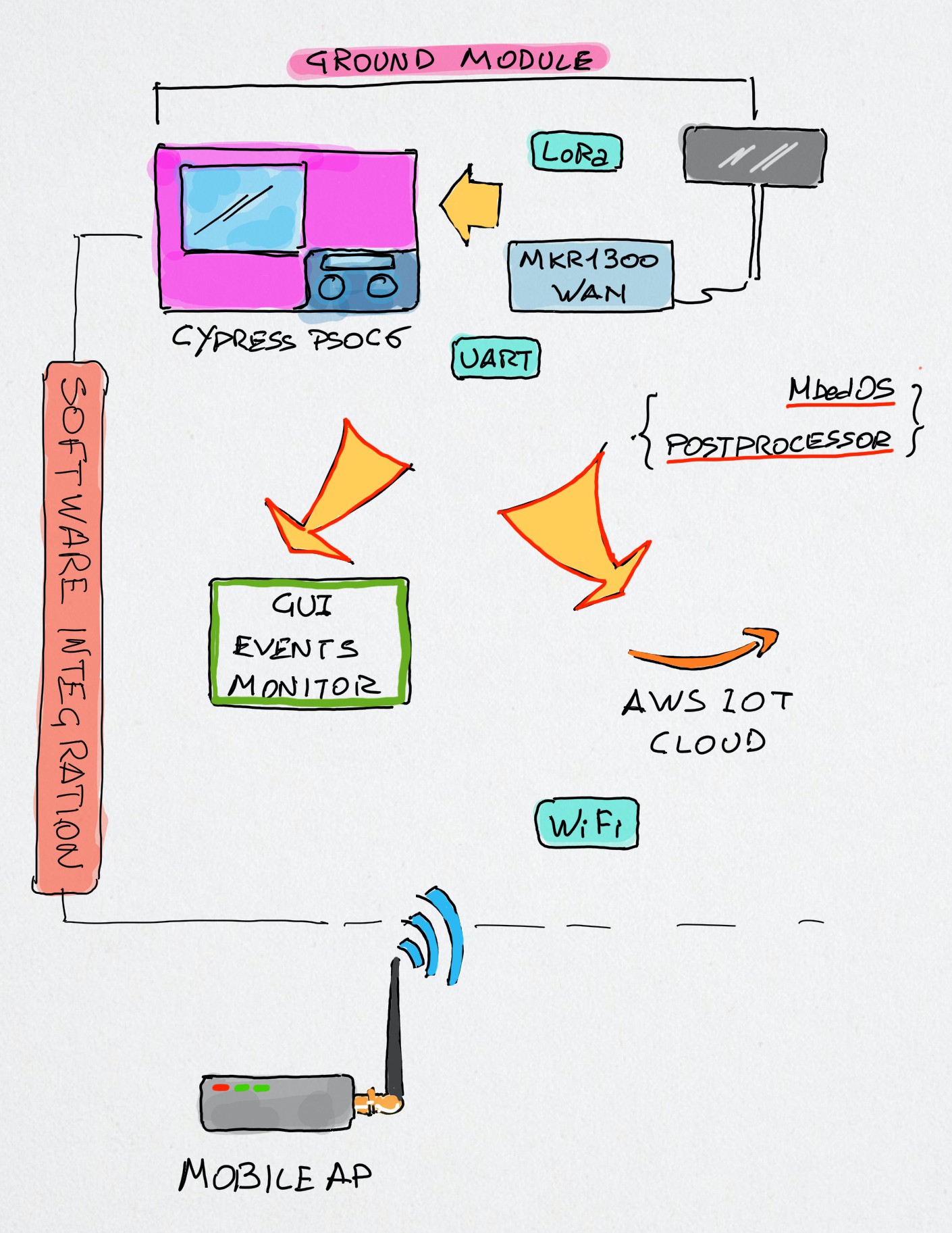
The above image shows the functional schema of the ground module application; one of the aspects I more appreciated of the PSoC6 architecture kit was the availability of may different kind of interfaces, including the USB host mode. In fact, the original software idea was to connect the MKR1300 LoRa receiver to the PSoC6 through the USB host port. Unfortunately, things were not so easy as I figured reading the hardware specifications of the PSoC6 Pioneer kit.
The USB UART example shown in the Modus Toolbox, as well as all the other examples I found on the Cypress site and GitHub refers to the USB-C connector (beside the USB host); the communication works perfectly only if on the other side there is a PC or any other device able to provide a USB host connection. But here I need to connect an Arduino!
I spent a lot of time investigating this (first) issue - I should thank the friend @Jan Cumps that helped me a lot investigating and suggesting tests to...
Read more »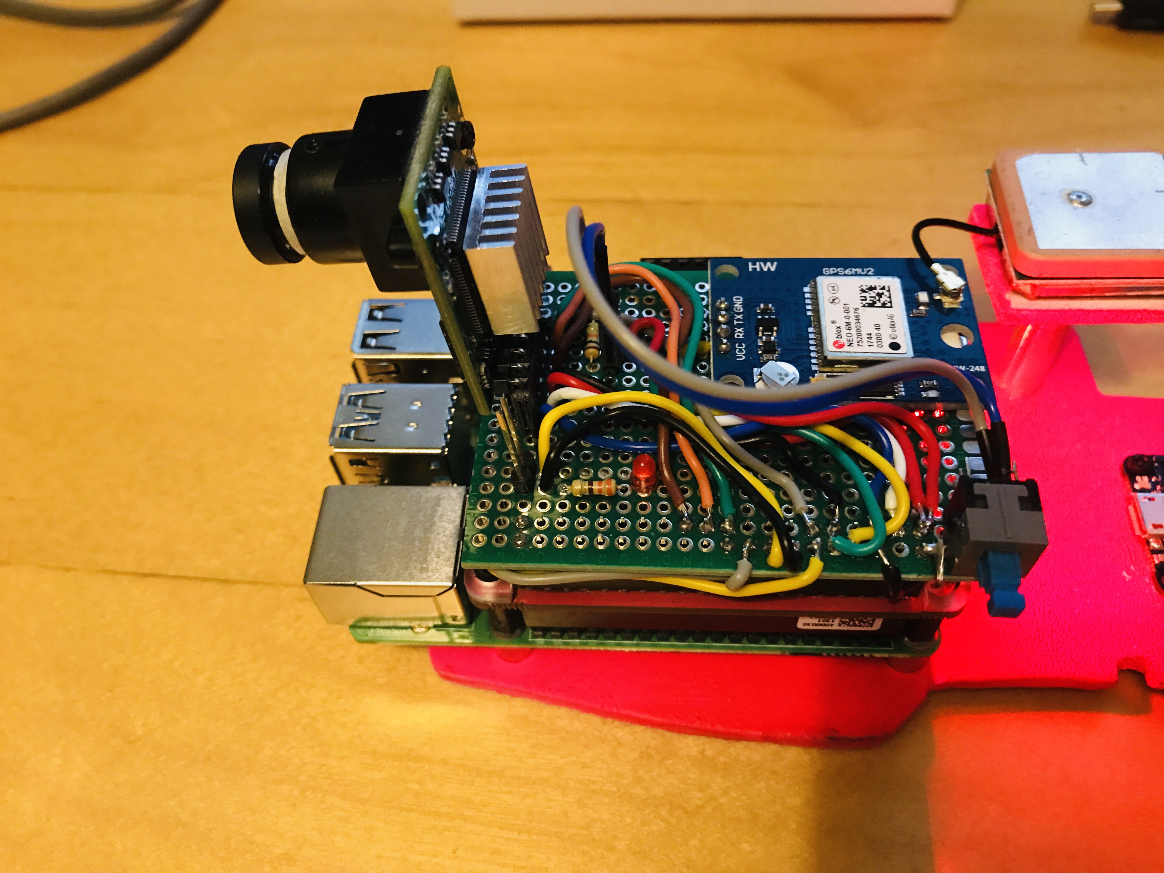


 Pratyush-Mallick
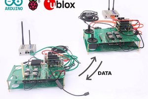
 Capt. Flatus O'Flaherty ☠
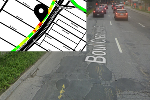
 Ashwin K Whitchurch