Close
0%
0%

USB Component Tester

Thumb-drive sized Universal Component Tester

Similar projects worth following
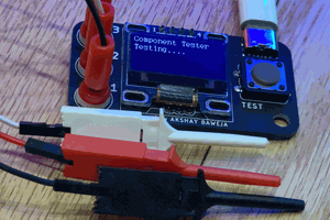
USB Component Tester is a universal testing device for electronic components with three or lesser pins. It can automatically detect the plugged-in electronic component and measure the desired component parameters without having the user to manually select the component type, unlike the multimeter. It is based on the popular AVR TransistorTester.
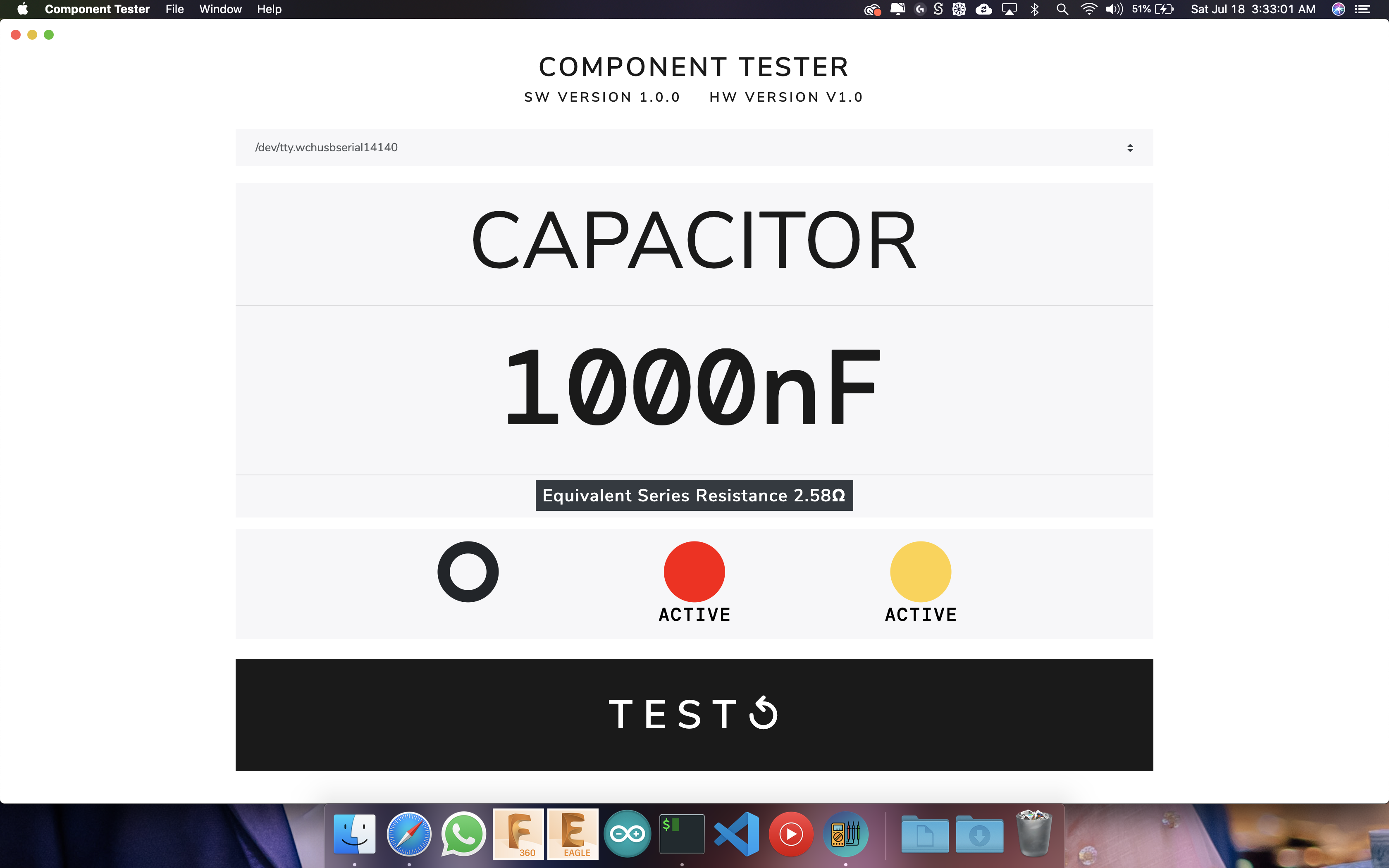
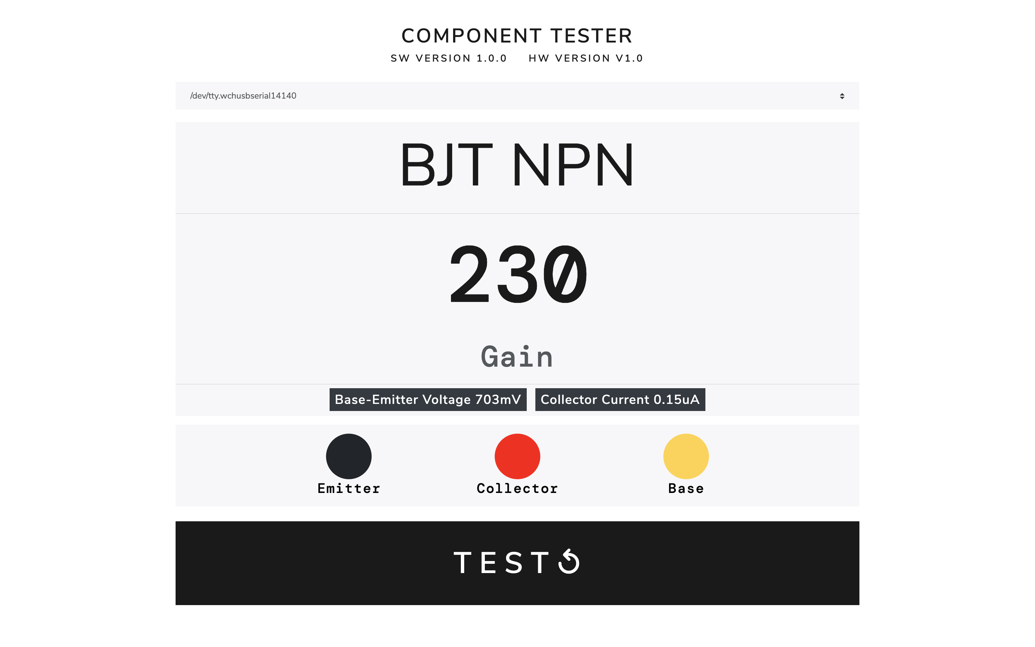
With a custom application built using electron, USB Component Tester provides the user with all desired component insights with a clean and minimal user interface. It works with all OS platforms like macOS, Windows, and Linux based systems. For MacBook Pro users, the application also supports TouchBar Interface.

Usually, many hobbyists, makers, or even engineers have a computer open beside them while working. This USB Component Tester adds a utility to the systems. It replaces other devices such as an ESR Meter, Function Generator, Capacitance Meter, etc. making the workspace free and allowing the user to work more freely.

Being an electronics engineer, I always wanted to have a portable component tester, which could test every electronic component out there. In 2016, I built myself a Component Tester based on AVR TransistorTester by Markus F. and Karl-Heinz Kübbeler. Following that, I redesigned the Component Tester to size of a keychain.

Since makers, engineers and hobbyists have a computer around our work-desk always. So I thought to myself why not build a component tester that could be used as a USB accessory which allow us to test the components. I have designed a software to go along with the USB component tester that displays the required test parameters on display in a minimal design form. The test leads are colour coded and these colours indicate the pin configuration. The software supports three major OS platforms macOS, Windows and Linux.

Supported Components

  • Resistor
  • Capacitor
    • with ESR
  • Inductor
  • Diode
  • Transistor
    • BJT
    • UJT
    • PUT
  • FET
    • JFET
    • MOSFET
  • IGBT
  • TRIAC
  • Thyristor

THANKS TO PCBWAY FOR SUPPORTING THIS PROJECT

ComponentTester.eep

Firmware File .eep file

eep - 2.43 kB - 07/23/2020 at 22:24

Download

ComponentTester.hex

Firmware File .hex file

hex - 79.71 kB - 07/23/2020 at 22:24

Download

GerberFiles.zip

For PCB Production

Zip Archive - 69.93 kB - 07/23/2020 at 22:23

Download

  • 2 × CAP CER 0.1uF 25V 0603 KEMET C0603C104K3RACTU
  • 3 × RES SMD 10K OHM 5% 1/4W 0603 Panasonic Electronic Components ERJ-PA3J103V
  • 1 × IC VREF SHUNT 1% SOT23-3 (LM4040-2.5) Texas Instruments LM4040DIM3X-2.5/NOPB
  • 1 × USB TYPE A PLUG SINGLE R/A PCB CUI Devices UP2-AH-1-TH
  • 2 × CAP CER 10000PF 25V 0603 KEMET C0603C103K3RACTU

View all 12 components

  • Application | Built using Electron

    Akshay Baweja07/27/2020 at 03:31 0 comments

    The application auto connects to component tester when a right port is selected by the user. The application is available for macOS 10+, Windows 8 and above and Linux.

    For macOS users, touchBar support is also provided.

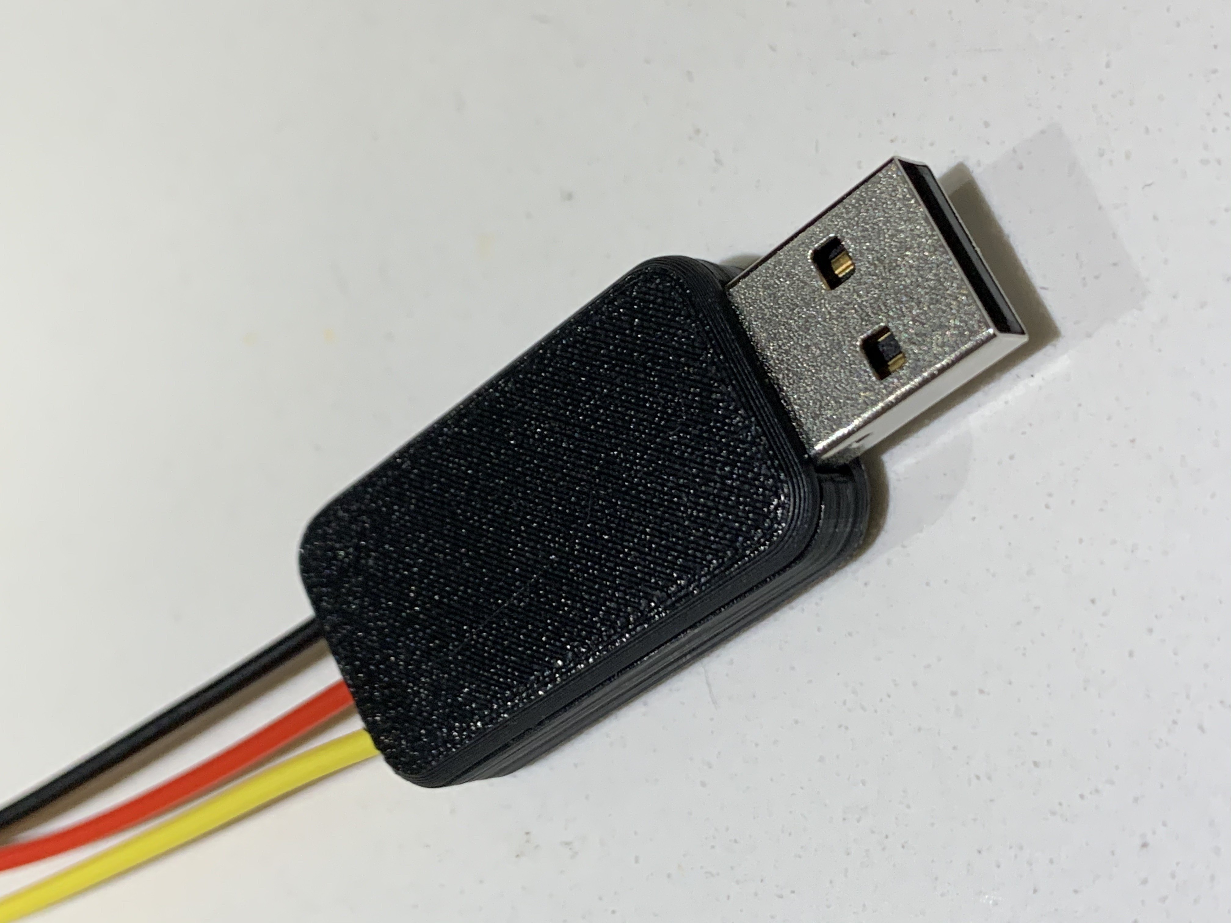
  • Designing a custom 3D Printed Case

    Akshay Baweja07/27/2020 at 03:26 0 comments

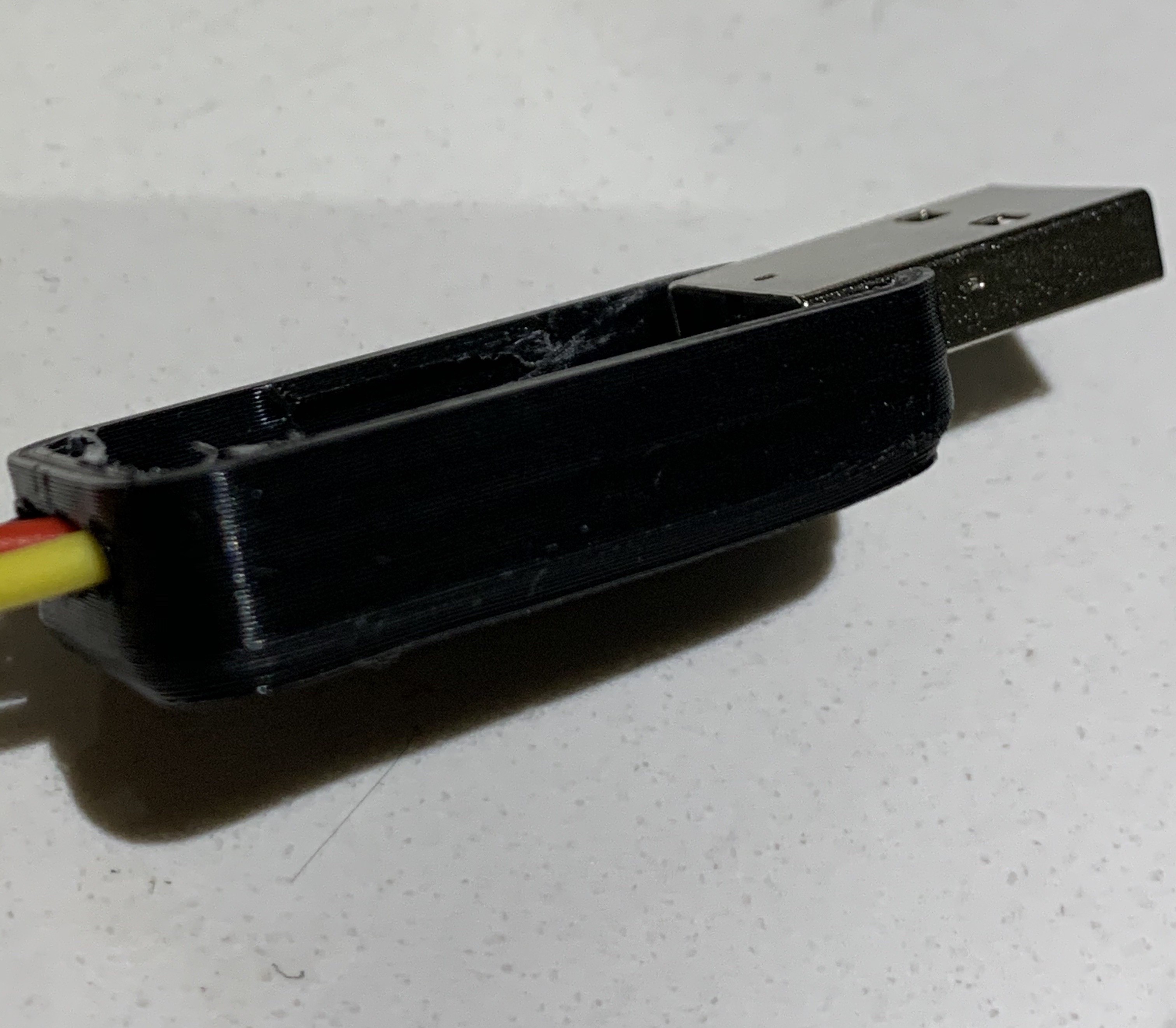
    I exported PCB design from Eagle to Fusion 360 and designed a case around it. The case is a 2 part design with snap fit design. The tolerances are pretty tight so it cannot be opened easily.

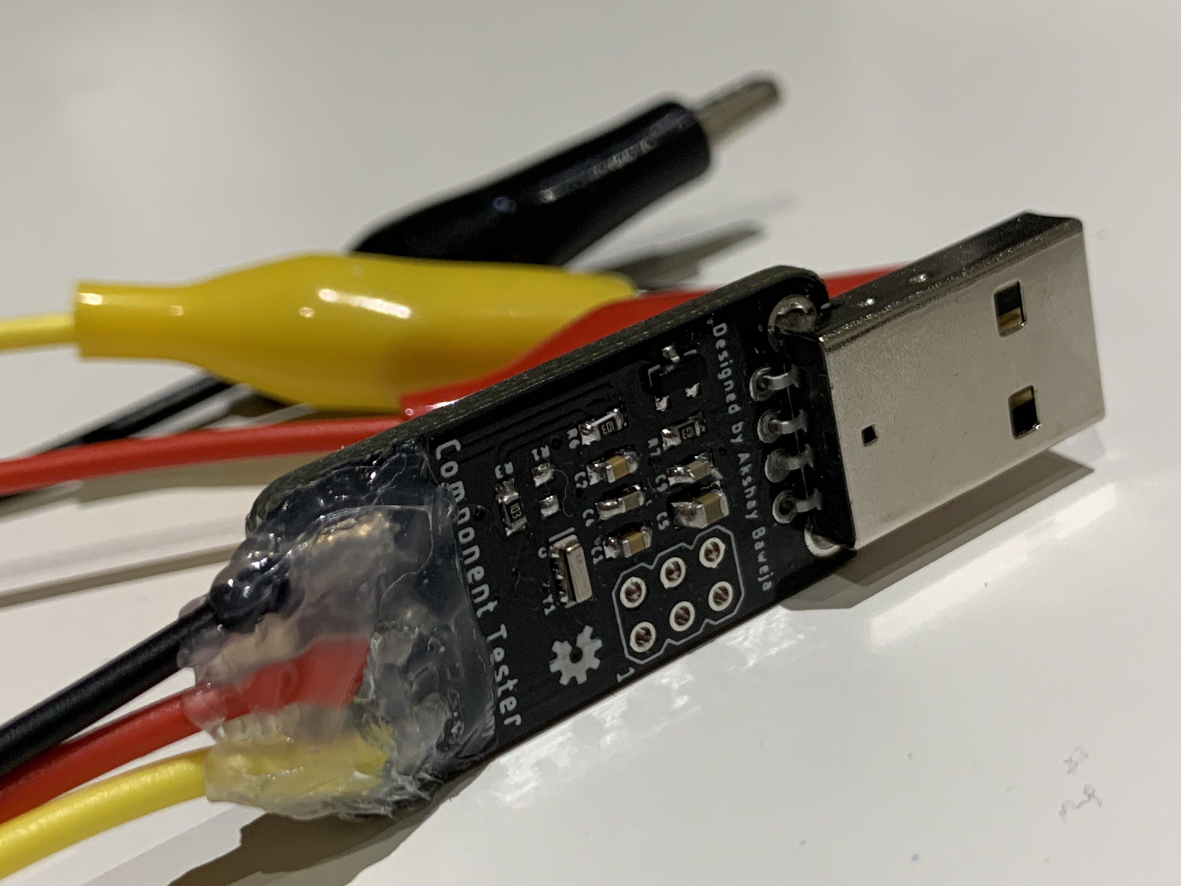
  • Soldering test wires to tester

    Akshay Baweja07/27/2020 at 03:15 0 comments

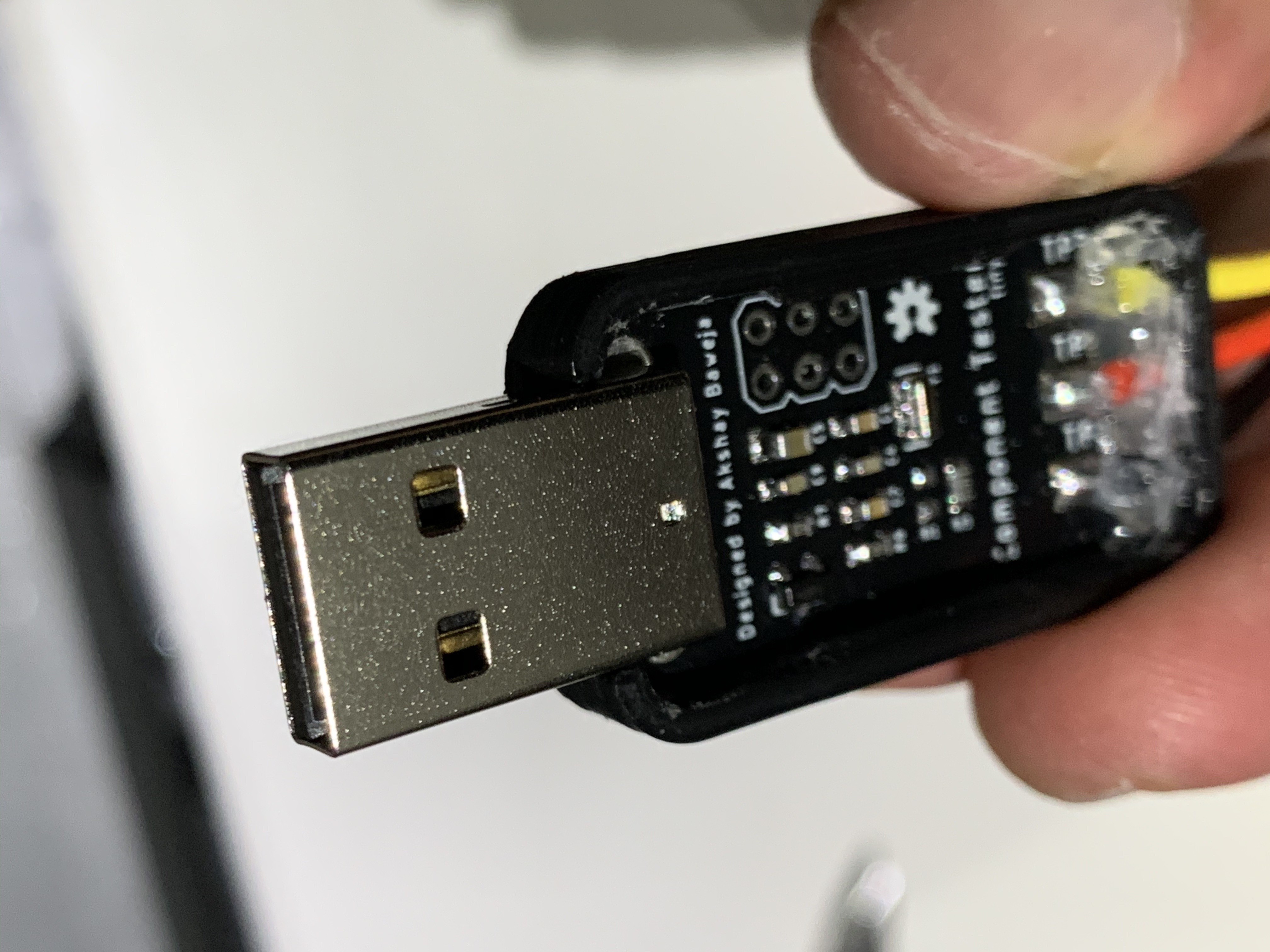
    I chose 3 different coloured wires to the tester. These wire colors will define the colors showing up in custom application. Supported colors are Black, Red, Yellow, Green and White. And added a bit of hot glue to keep the wires in place.

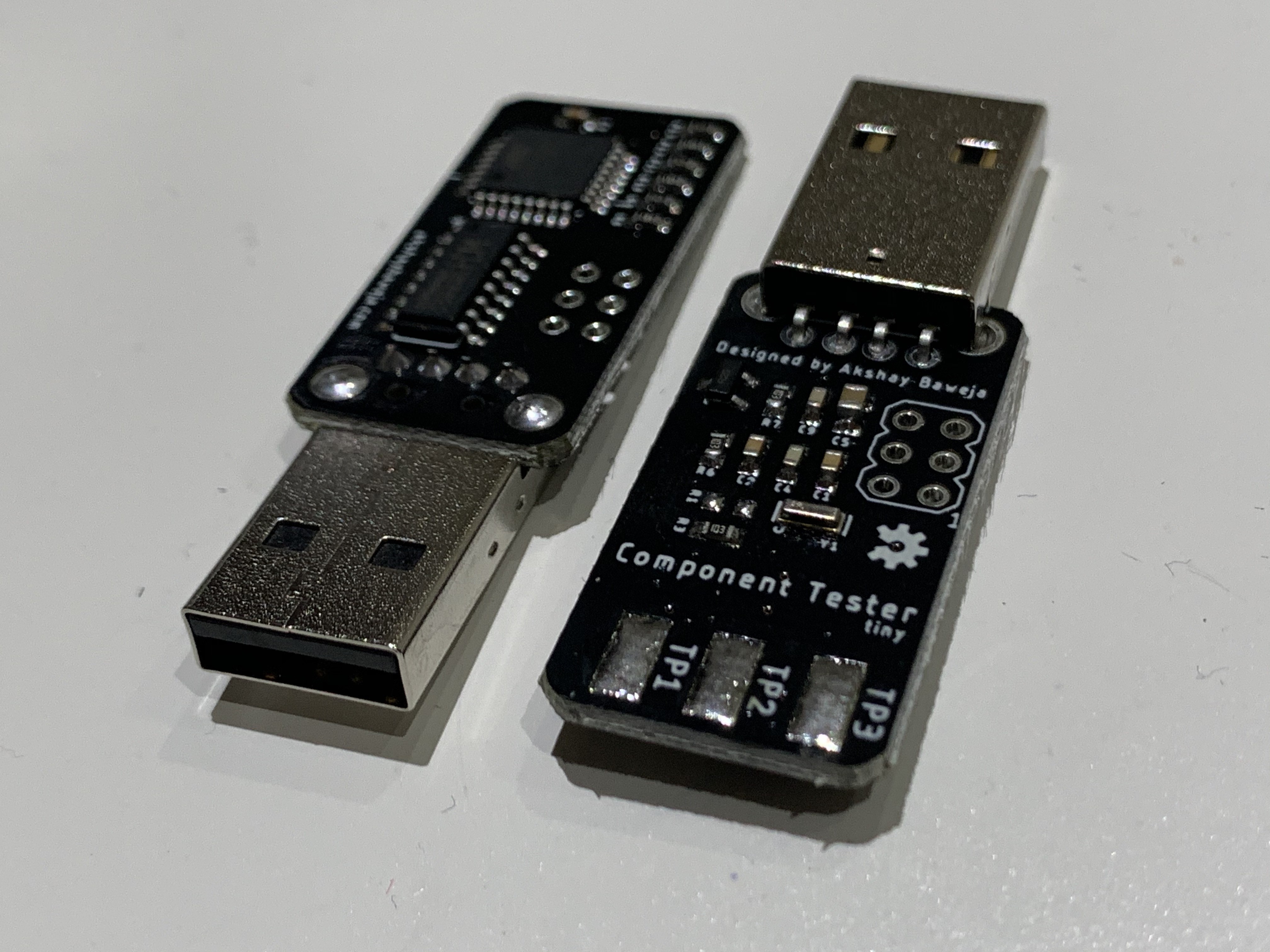
  • The Assembled PCB Review

    Akshay Baweja07/24/2020 at 06:01 0 comments

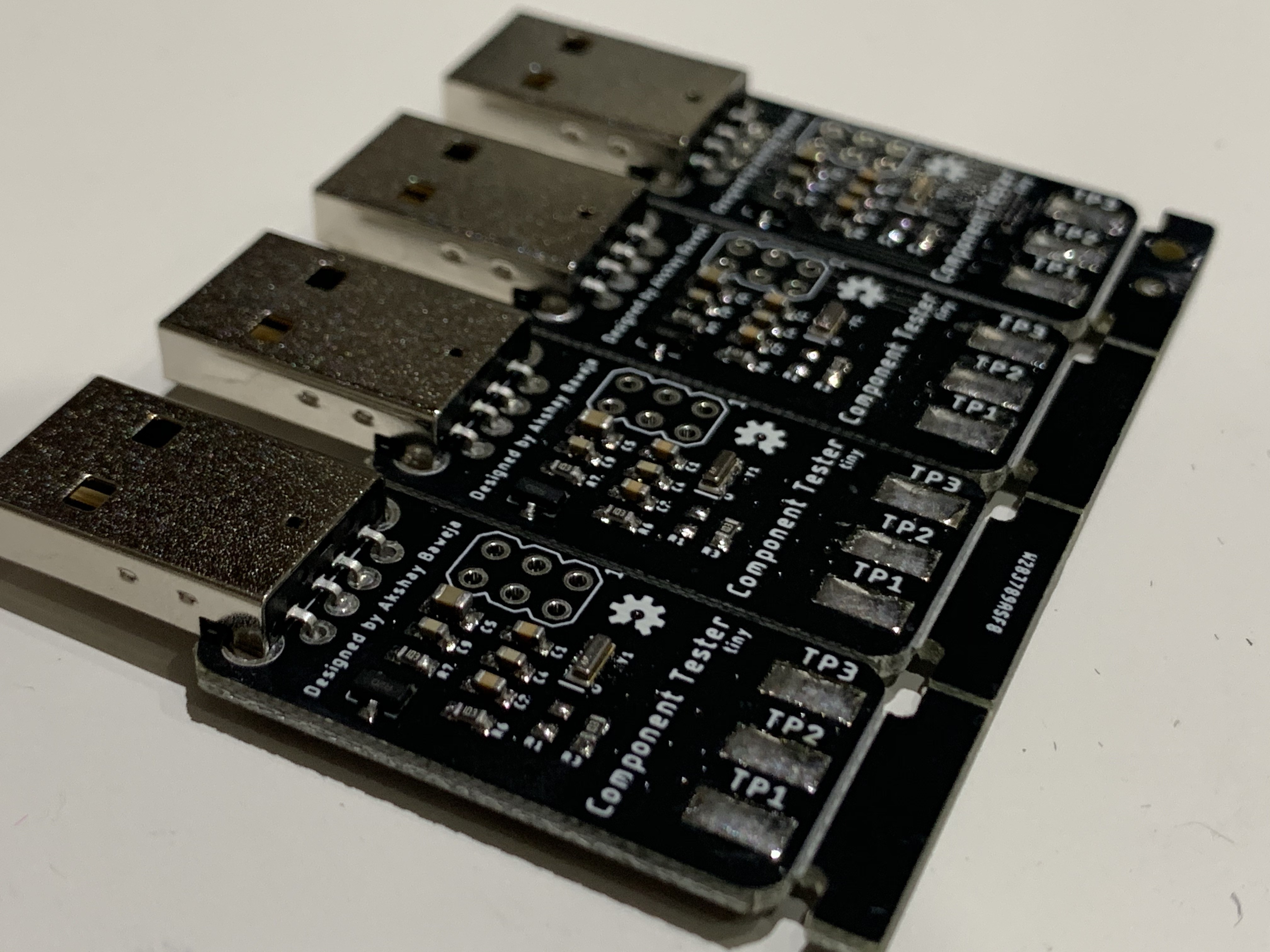
    PCBWay did a great job at assembly service. The components look very neatly soldered and are genuine components as presented by me in the BOM.

  • PCBs Arrived from PCBWay

    Akshay Baweja07/24/2020 at 05:55 0 comments

    A huge thanks to PCBWay's Prototyping and Assemble Service for getting my boards fabricated and assembled. They offer great quality boards for a very low and affordable price. They also offer a variety of solder mask options to try. Currently they are running an amazing offer for assembly service, you can get 20 boards assembled for just $30 with free shipping.

    USB Component TesterAlternatively, you can click the left image to order PCBs directly from PCBWAY. The assembly service was great and turned out to be amazing and the soldering looks great.

  • PCB Design - Sponsored by PCBWay

    Akshay Baweja07/23/2020 at 22:19 0 comments

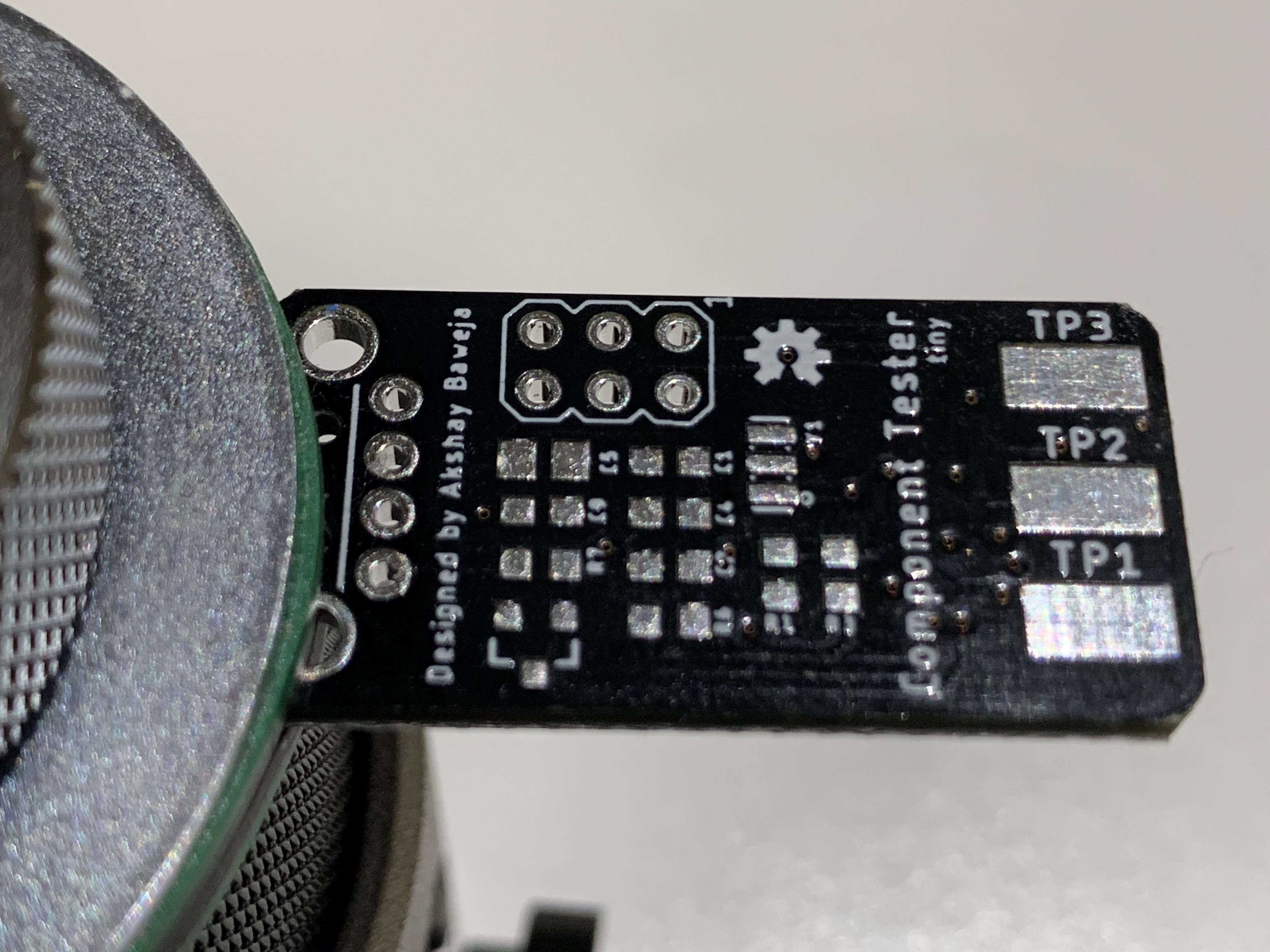
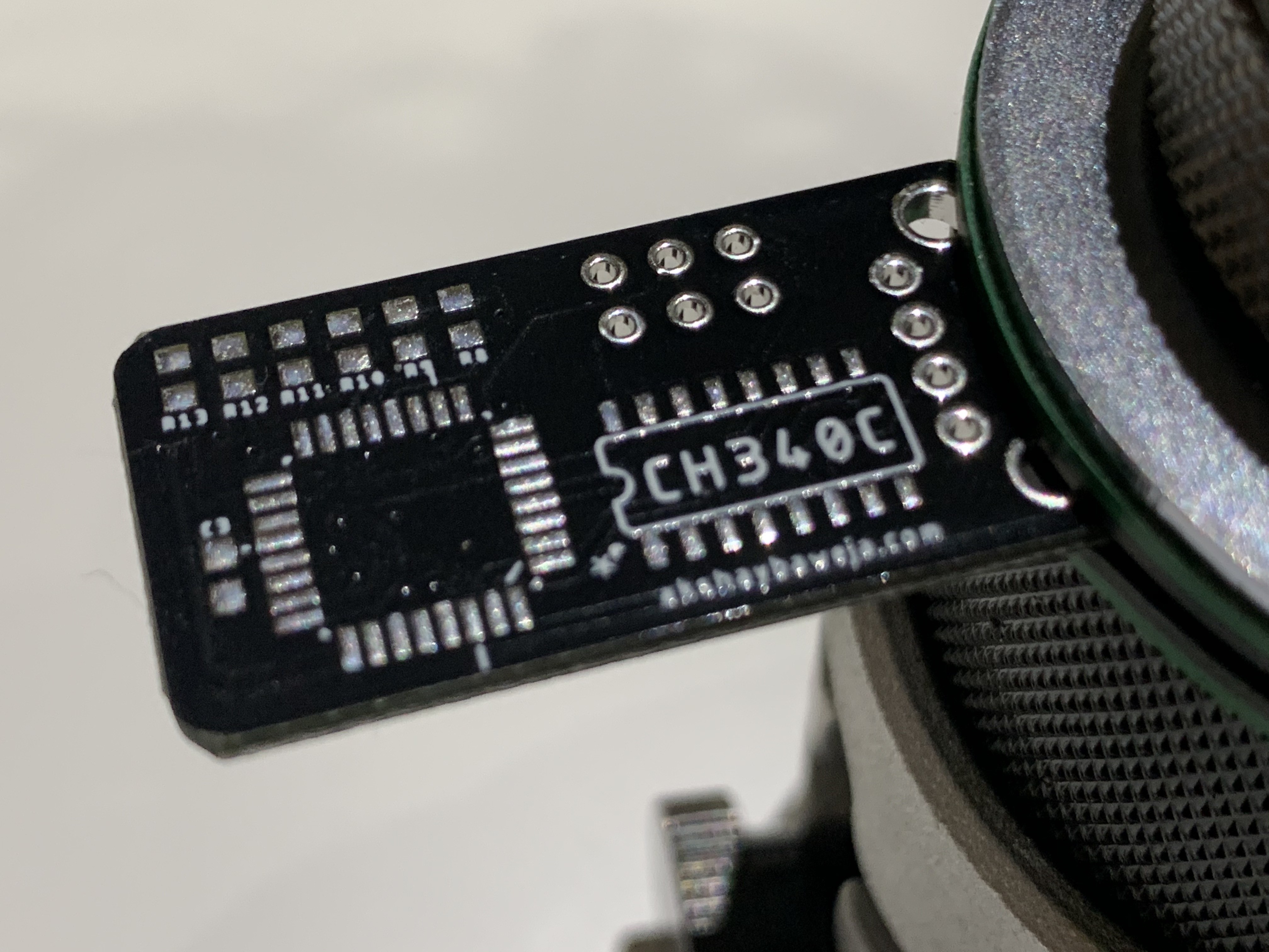
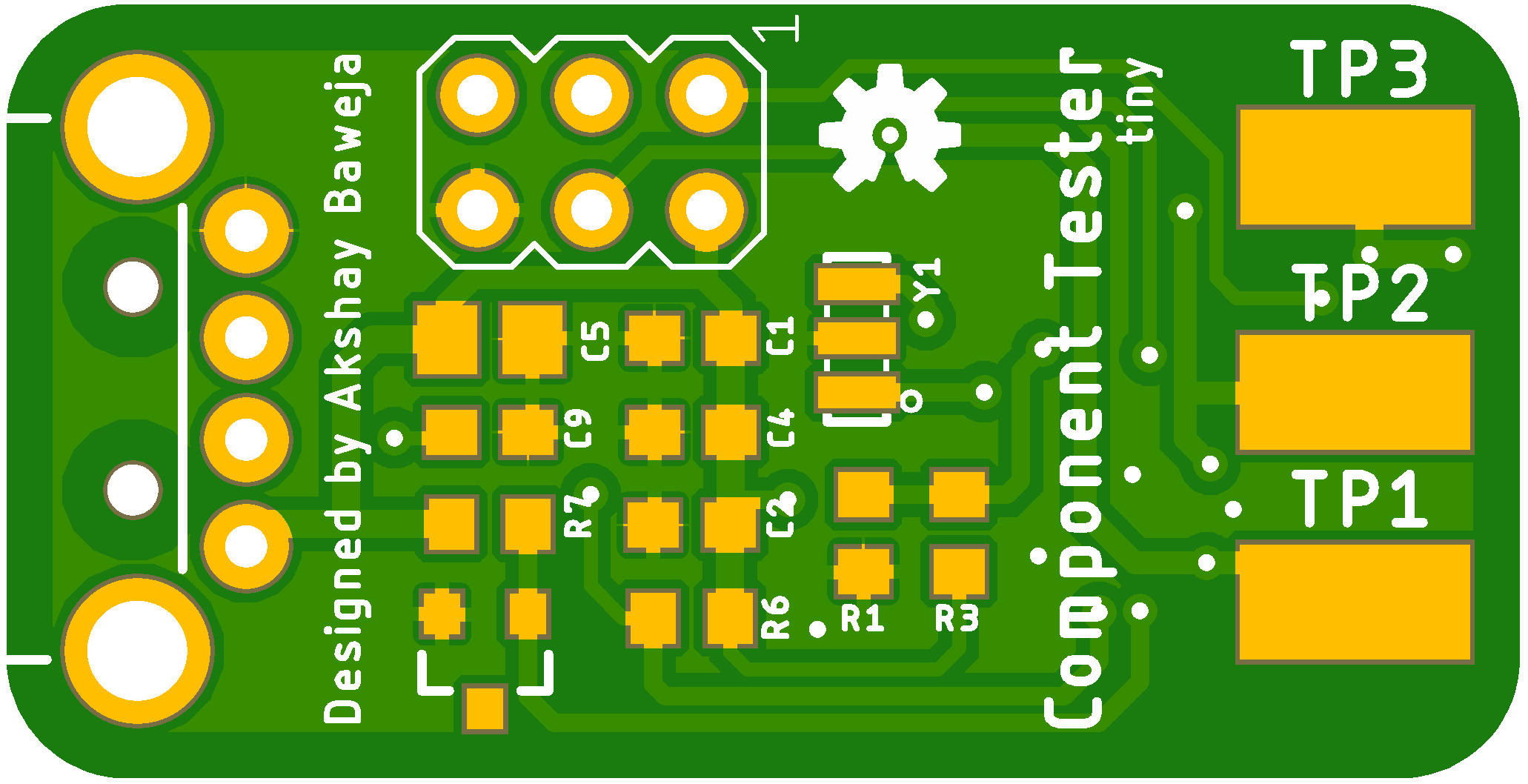
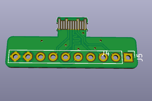
    The PCB is designed to be the size of a thumb drive with male USB-A connector. The 3 Test Pads are exposed for soldering the test leds onto them. The dimensions of PCB are approximately 34mm x 17mm.

    USB Component Tester
    USB Component Tester

View all 6 project logs

  • 1
    Application Download

    The application is free to download from GitHub 

  • 2
    Burning the Firmware to USB Component Tester

    ⚠️ REQUIRED

    • You will need USBasp to burn firmware files to tester.
    • You must have AVRDUDE installed in your system in order for following instructions to work.

    In Terminal/Command Prompt, navigate to folder's location with firmware files and execute the following commands-

    // Setting fuses for MCU
    avrdude -c usbasp -B 200  -p m328p -P usb  -U lfuse:w:0xe2:m -U hfuse:w:0xd9:m -U efuse:w:0xfc:m
    // Flashing .hex and .eep files to MCU
    avrdude -c usbasp -B 20  -p m328p -P usb -U flash:w:./TransistorTester.hex:a -U eeprom:w:./TransistorTester.eep:a

View all instructions

Enjoy this project?

Share

Discussions

zhang wrote 08/25/2021 at 02:57 point

I made a copy, and it turned out that this problem occurred. I checked all the hardware and there is no problem. I also checked that the firmware and fuse position are correct and there is no problem. Please help me, thanks!

After running the desktop software for the first time to select the port, the software does not display the "Test" button or the hardware version, and then reselect other ports and return to the correct tester port, prompting "Serial port error open COM2: Access denied"

  Are you sure? yes | no

.io wrote 06/26/2021 at 10:09 point

Would you be willing to publish your case design?

  Are you sure? yes | no

niuyingxian wrote 08/01/2020 at 22:20 point

Can I measure voltage? What is the scope? Thank you

  Are you sure? yes | no

Akshay Baweja wrote 08/02/2020 at 02:31 point

Hey,

No this version cannot test voltages for now.

  Are you sure? yes | no

Martin wrote 07/28/2020 at 09:45 point

Could this also be used with smartphones with USB-OTG capability?

  Are you sure? yes | no

Akshay Baweja wrote 07/28/2020 at 15:45 point

Hey,

Surely it has capability to be used with android devices. I’m currently working on the android app.

  Are you sure? yes | no

Ken Yap wrote 07/28/2020 at 04:42 point

I assume those holes on the PCB are for burning the firmware. What would be nice is a companion board with connector posts for the crocodile clips and a ZIF socket for inserting component under test. When doing say a whole bunch of transistors, the clips are unwieldly.

  Are you sure? yes | no

Akshay Baweja wrote 07/28/2020 at 06:46 point

Hey,

Yeah those holes on PCB are for burning the firmware. I plan to use test hooks for shipping than providing with additional board. Test hooks are compact and tiny and can be easily hooked to transistors without bending legs of transistors or any other 3 pin component.

  Are you sure? yes | no

Similar Projects

Does this project spark your interest?

Become a member to follow this project and never miss any updates