Close
0%
0%

Restoring the TRANSBINIAC computer

Bringing a vintage DIY binary counting computer back to life

Similar projects worth following
A mystery find on Craigslist turned out to be the "TRANSBINIAC." A circa-1960 homemade binary counter using transistorized flip-flop circuits. Most likely someone's science fair project or a teaching tool, built from plans published in a 1960 Electronics Illustrated. Let's get it going!

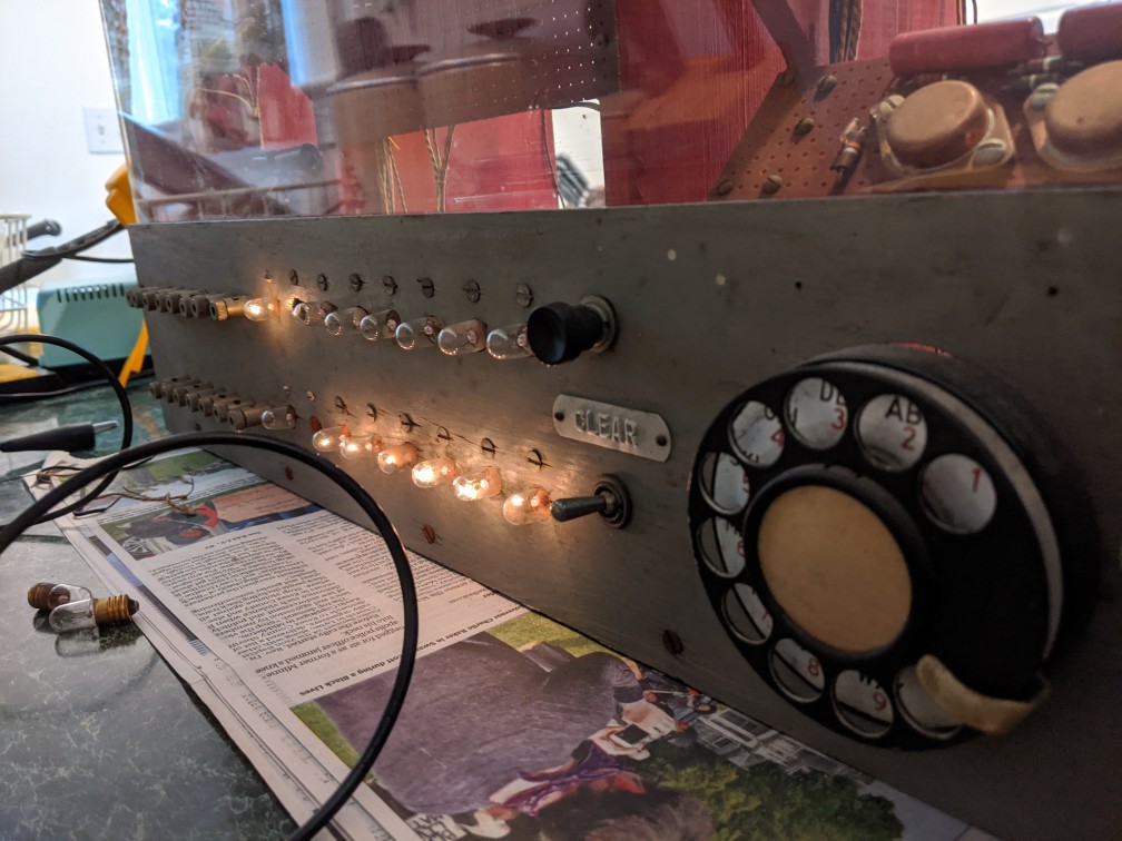
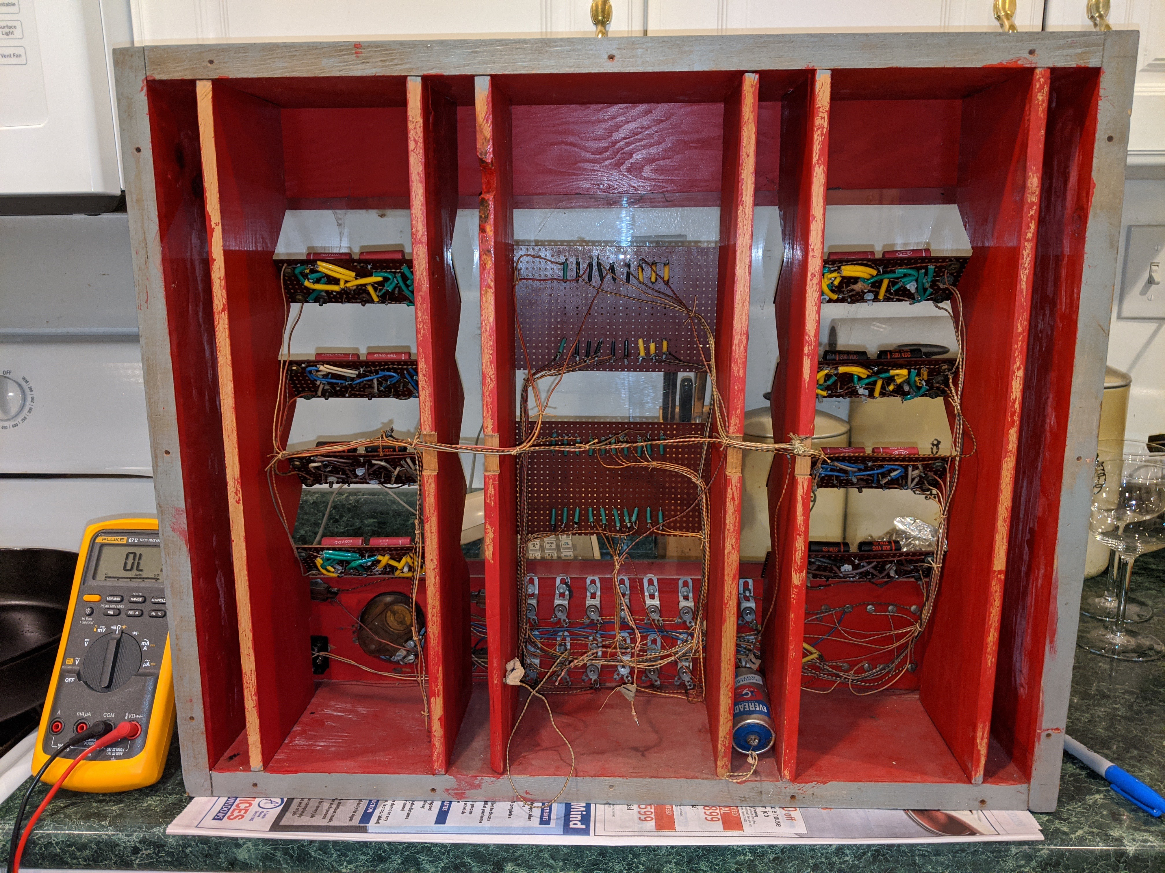
I discovered this by accident while looking for tools and power equipment. Cost a whole $25 in a lot that included a nice old VHF signal generator. The cabinet design is very dramatic (bright colors and windows in your computer case are nothing new, sorry gamers) and seems to have been built for an impressive stage presence. The operation position is a roughly 45° angle, thanks to a built-in kickstand on the back.

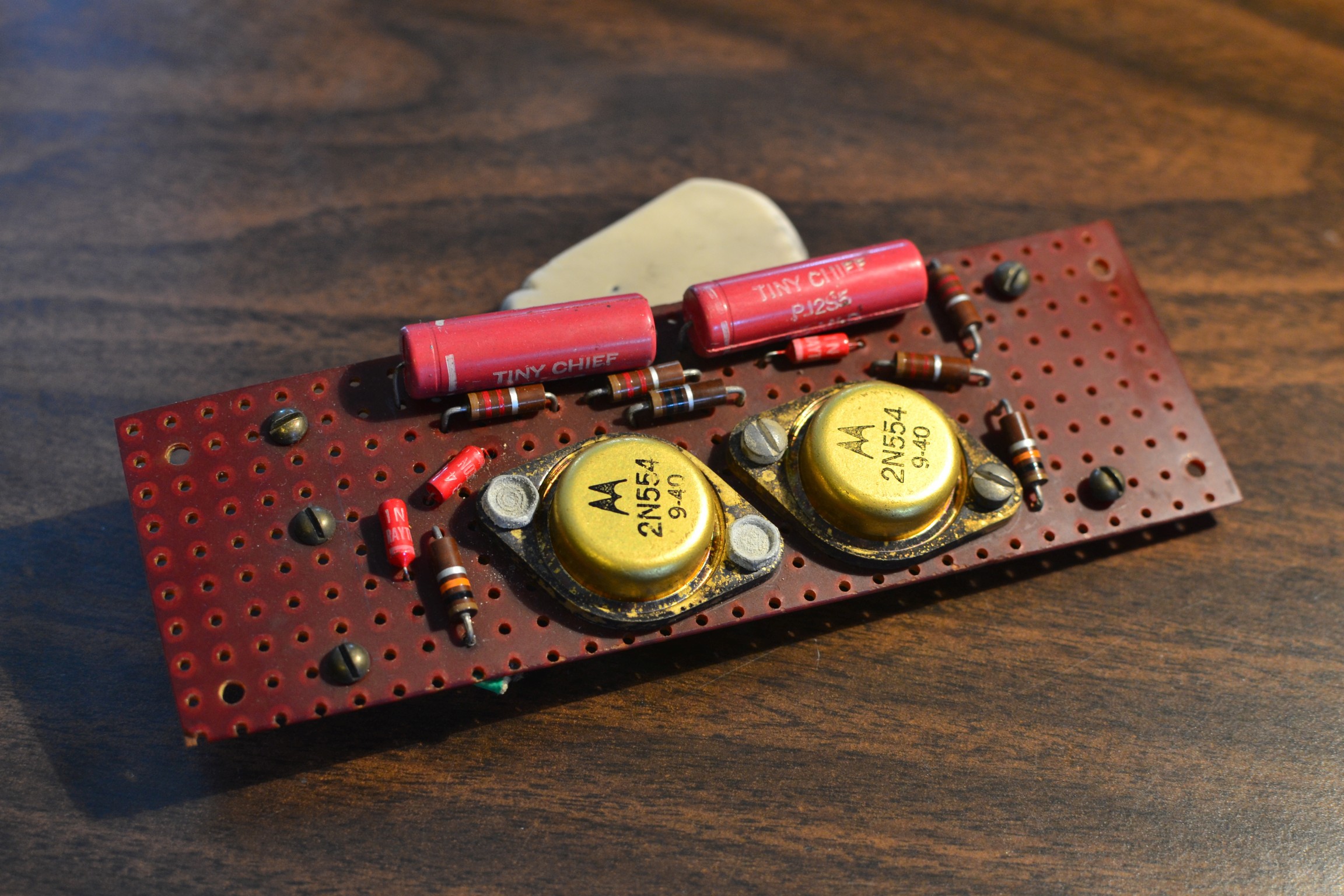
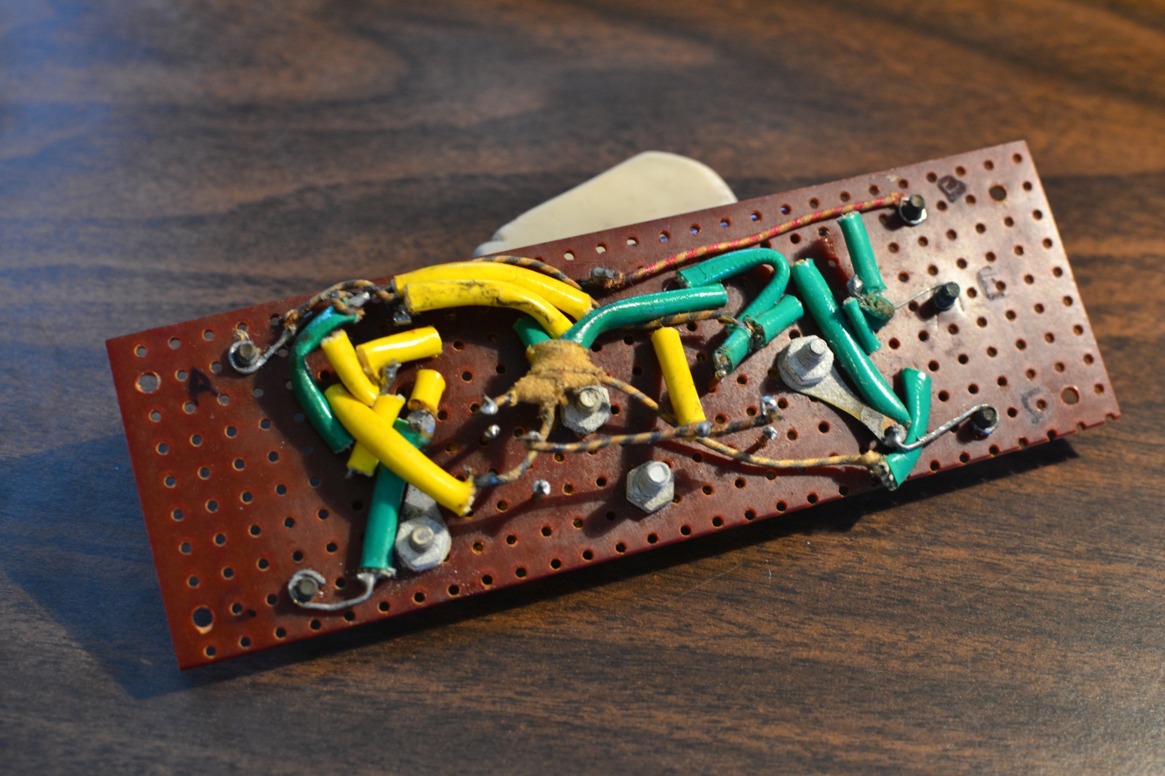
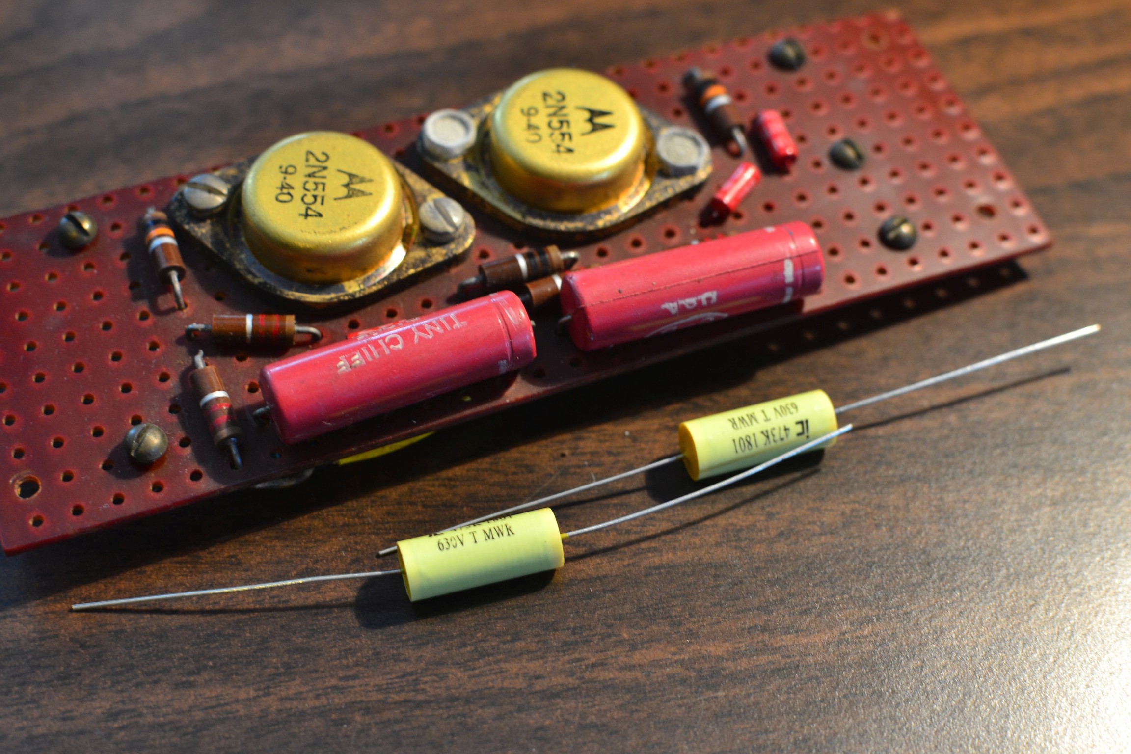
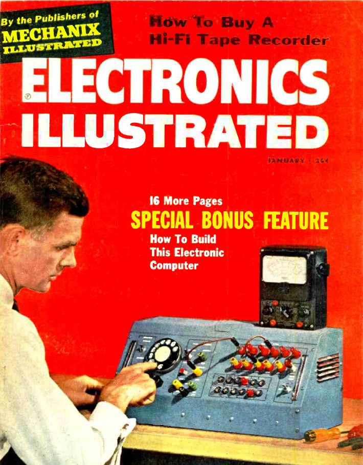
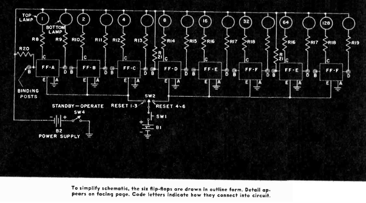
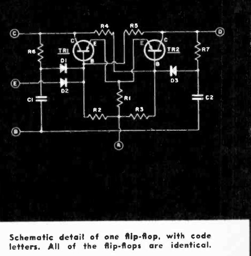
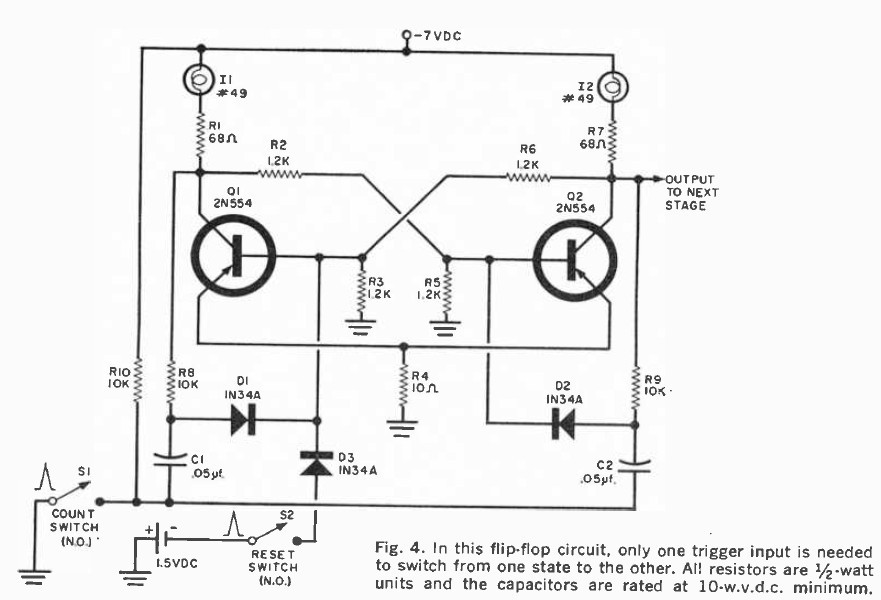
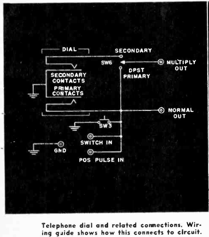
Science fair project? Classroom demonstration? The innards are a modified version of the plans published in the January 1960 issue of Electronics Illustrated. Major differences being eight modules instead of six, and the deletion of the multiplication circuit All the components date from before 1962 or so. The guy who built this must have been one of the few people in the world to have anything involving solid-state logic in their house at the time.

Requires some minor repair and perhaps some re-engineering to make it fully functional. Looking forward to being able to count to 255 without using my fingers.

  • Flip-flop in detail

    John09/07/2020 at 20:37 1 comment

    Here's a closeup on one flip-flop module (#1 in the machine's sequence, or top-left as seen in the main photos.) The construction obviously shows skill, although I'm guessing not a lot of formal training. Lots of odd wiring choices that I feel like could have been done in a more straightforward way. He was a fan of compound joints with many connections coming together.

    In that pic I have a few joints desoldered for testing purposes. Another odd choice is that two of the other modules have their transistors installed upside down. Rather than just flip them over to make all the units identical, he wired those two modules in mirror fashion--confusing. I can't tell if they all were made at the same time or not. The parts aren't identical from unit to unit but whether that means they were done at different times or just used whatever was on hand I can't say.

    All the original caps have drifted way off, but the resistors check out and the transistors seem OK, although with a little more leakage than you'd want in a modern piece. Some people have brought up keeping the original caps for aesthetic reasons and hiding the new ones. I don't really mind the new ones and I like the snazzy yellow, but what're your thoughts? I'll rebuild this soon and test it out.

  • Getting my flips to flop?

    John08/27/2020 at 17:57 0 comments

    The core of this thing are eight bistable flip-flip modules each based around two germanium 2N554 transistors. As-found the machine will power up and illuminate some of the output lights, but the flip/flip triggering is very erratic. Most modules need to be triggered multiple times before switching outputs. Any readers have thoughts on the problem?

    Naturally he original sealed paper .05uF 100V capacitors are all suspect at this age. Most measure several times the rated capacitance and show signs of electrical leakage. My first experiment was replacing the caps in one module with a pair of random (0.85uF) known-good films caps I had on hand. The triggering improved a little but is still very unreliable. Correct caps have been ordered, but I'm wondering how much could a drifted cap affect the circuit's function?

  • Discovering the electronic layout

    John08/27/2020 at 17:26 0 comments

    This machine appears to have been built using the Jan 1960 Electronics Illustrated version of the plans as the starting point. Other magazines such as Popular Electronics have different descriptions of the same fundamental circuits. Member @Yann Guidon / YGDES has published several logs going into the historical detail of the design.

    Compared to the published machine, the Transbiniac has two extra flip-flop modules and a supporting 10K resistor, the multiplication circuit is gone, some of the wiring has been simplified, and there's no AC power supply. I've altered the original overall schematic to reflect the added modules:

    The flip-flops themselves appear to be unchanged from the original published designs. One from the Electronics Illustrated article and another from the March 1961 issue of Popular Electronics:

    The last change/difference is one I can't tell if it's intentional or not. The original plans call for a normally open trigger circuit consisting of a momentary switch plus a rotary telephone dial. In my machine, the switch and the rotary dial are both wired as NC and don't appear to work in that configuration. My dial also doesn't appear to have the same switch type as the published plans, but my vintage telephone kung fu is pretty weak.

View all 3 project logs

Enjoy this project?

Share

Discussions

John wrote 09/07/2020 at 19:49 point

That's awesome, thanks!

  Are you sure? yes | no

Starhawk wrote 09/07/2020 at 22:24 point

indeed! Also: dear [Hackaday Staff], being able to +Like a single comment/etc would be supremely awsome...

  Are you sure? yes | no

Yann Guidon / YGDES wrote 09/08/2020 at 01:08 point

[+] :-)

  Are you sure? yes | no

Starhawk wrote 09/07/2020 at 22:28 point

@Yann Guidon / YGDES  Oh, sorry, meant to ask... one of the logs in this project mentions specifically that you have a collection of sorts (impromptu, I assume!) of additional/revised circuit diagrams for this thing... but I don't see a link in that log and it's not immediately obvious on your own profile where they might be... can you point me, please, to where I might easily find them...?

  Are you sure? yes | no

Yann Guidon / YGDES wrote 09/08/2020 at 01:02 point

@Starhawk  I created a group at https://hackaday.io/project/8449-hackaday-ttlers to discuss this subject, explore the tricks of the previous millenium and figure out how the heck they made these stuff work :-D

I'm not sure what exact diagram was mentioned though. I know I have studied these old 2N544 Flip flops when I explored Germanium circuits and that's probably where I came across the EI diagrams.

  Are you sure? yes | no

Starhawk wrote 09/08/2020 at 01:39 point

@Yann Guidon / YGDES he didn't mention a specific one, just that there were a bunch of them. I'd be more interested, in particular, in schematics of similar machines... PM me if you want to ask why, there's a story there and it's looong.

  Are you sure? yes | no

Andrew Yeomans wrote 09/06/2020 at 20:22 point

Neat device! I'll have to power up a similar binary counter that I built around 1970. It too had telephone dial and some push buttons for each flip-flop.

  Are you sure? yes | no

Michael wrote 09/03/2020 at 09:20 point

Pretty cool find. I think you'll get it working. I think R1/C8 (for instance) are intended to be for switch debounce. I also think the normally closed switches vs normally open switches in the design are a mistake. The circuit design appears to be to trigger on the positive edge. A normally closed switch would require the opposite. I would verify the resistors and capacitors are within tolerance, replace them if they aren't. Capacitors unless they are mica (not likely) should be replaced unless you want to look good but not necessarily be reliable. If they fail as a short you might lose the much harder to replace transistors.

  Are you sure? yes | no

John wrote 09/03/2020 at 14:53 point

The original caps are sealed paper and measured about 5X the correct uF value. I have a set of brand new poly caps that just arrived so we'll see how that works out. All the resistors I've measured so far have been spot-on. The transistors show more leakage than I'd expect, but I assume that's a germanium vs silicon thing.

  Are you sure? yes | no

Michael wrote 09/03/2020 at 15:00 point

Perfect. If the original builder was true to the schematic, as far as the one pass RC filtering on the input goes, the NC / NO problem will need to be solved. I'm looking forward to seeing how this goes for you. Leakage is a big thing for the caps. They turn into resistors over time. If I can find the link to a fairly simple but reliable leakage test I'll post it

  Are you sure? yes | no

John wrote 09/03/2020 at 15:51 point

Re: the triggering switch state, I'm just going to wire it for NO the way the schematic shows. Everything else about this was built using those plans and I'm operating under the assumption the NC connection is a mistake.

  Are you sure? yes | no

cr0sh wrote 09/03/2020 at 01:29 point

Pretty amazing find! I have enough junk in my "computer museum" as it is, but I'd still love to have something like this. I hope you're able to get it working again! BTW - facebook has a "vintage and surplus electronics" trading group you might want to check out, if you want to restore this with original components, they might be able to hook you up with the parts.

  Are you sure? yes | no

dbcorbin wrote 09/02/2020 at 20:42 point

I love this old stuff.   But it is old.   I think you should take a look at the lamp resistance.  I am guessing they are running about 8mA... but if one of them is higher resistance then the voltage at the base of the transistors would not be balanced.   I had some lamps from 50 year old telephone equipment found in my father's spare parts drawers... "brand new" but when playing with them, i had quite different V drop across a set of 20 or so lamps.  different brightness too.

  Are you sure? yes | no

John wrote 09/03/2020 at 14:50 point

Cold or hot resistance? They all measure different when cold, but they draw the same current when they're illuminated under power.

  Are you sure? yes | no

Harvey Sugar wrote 08/31/2020 at 19:14 point

I actually built one of these when I was 13 but that was in 1964. It was my introduction to digital electronics. Mine had  6 flip-flops and was not so neat. The flip-flop board were spread out on a piece of plywood. Eventually it included an adder and a rudimentary control unit and could read numbers off of Teletype paper tape and punch the result on another paper tape.

  Are you sure? yes | no

John wrote 09/03/2020 at 14:49 point

Neat. What did the control parts consist of?

  Are you sure? yes | no

Harvey Sugar wrote 09/08/2020 at 07:31 point

The control logic consisted of a ring counter and a diode matrix. Each output of the ring counter represented a step in the machine cycle. These were connected by diodes to the control lines. The actual parts were surplus germanium switching transistors and diodes. Many of the parts were unmarked but roughly equivalent to 2N404s for the transistors and 1N34s for the diodes. 

  Are you sure? yes | no

Dr. Cockroach wrote 08/30/2020 at 12:31 point

Man oh man, what a find and so glad you rescued it. My dream would be to find something like that at a Hamfest someday.

  Are you sure? yes | no

Tom Nardi wrote 08/30/2020 at 06:26 point

What a phenomenal find, thank you for sharing this with us.

  Are you sure? yes | no

Yann Guidon / YGDES wrote 08/29/2020 at 13:16 point

This is too insane to ignore !

Great work John :-)

  Are you sure? yes | no

Similar Projects

Does this project spark your interest?

Become a member to follow this project and never miss any updates