 Tauno Erik
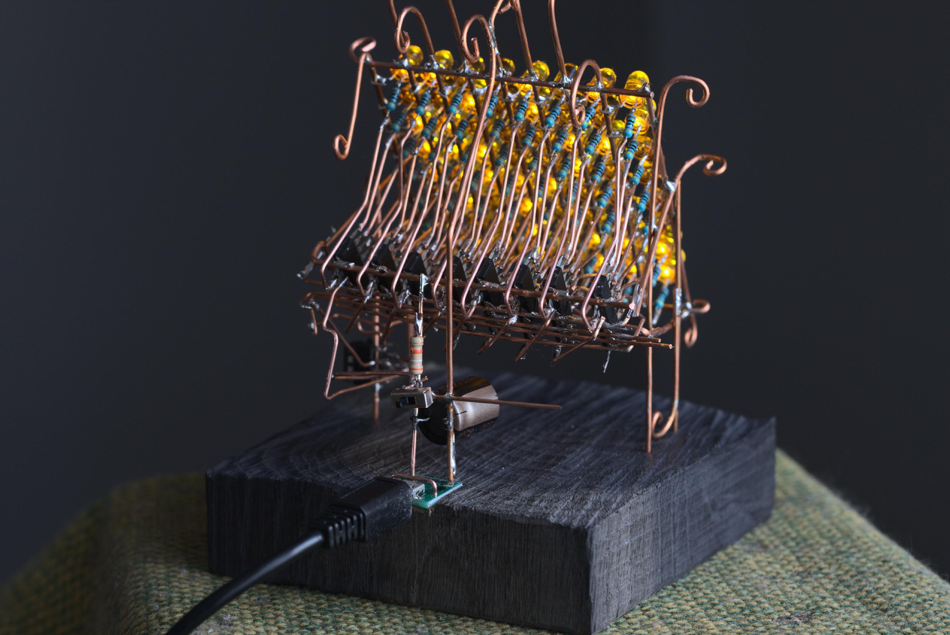
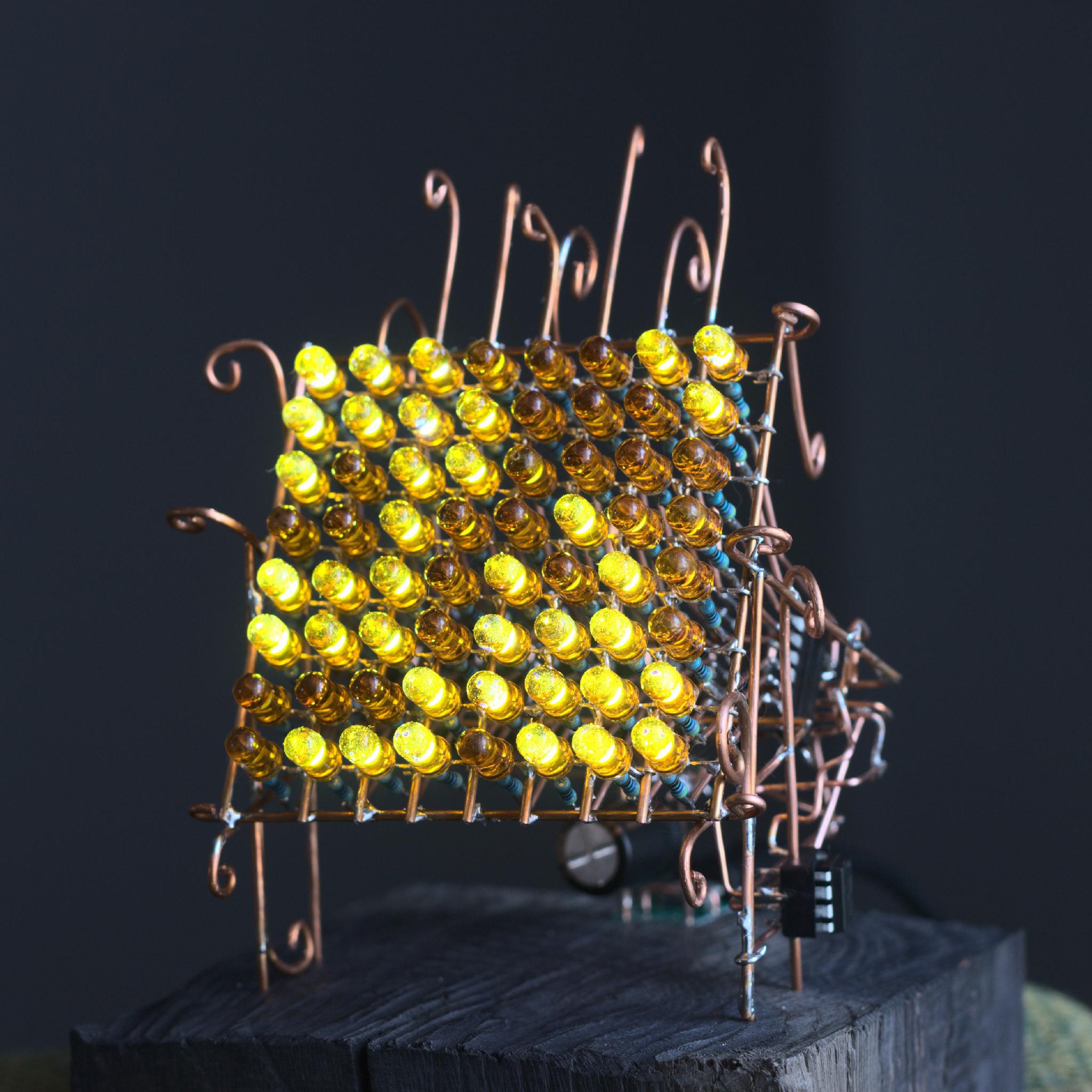
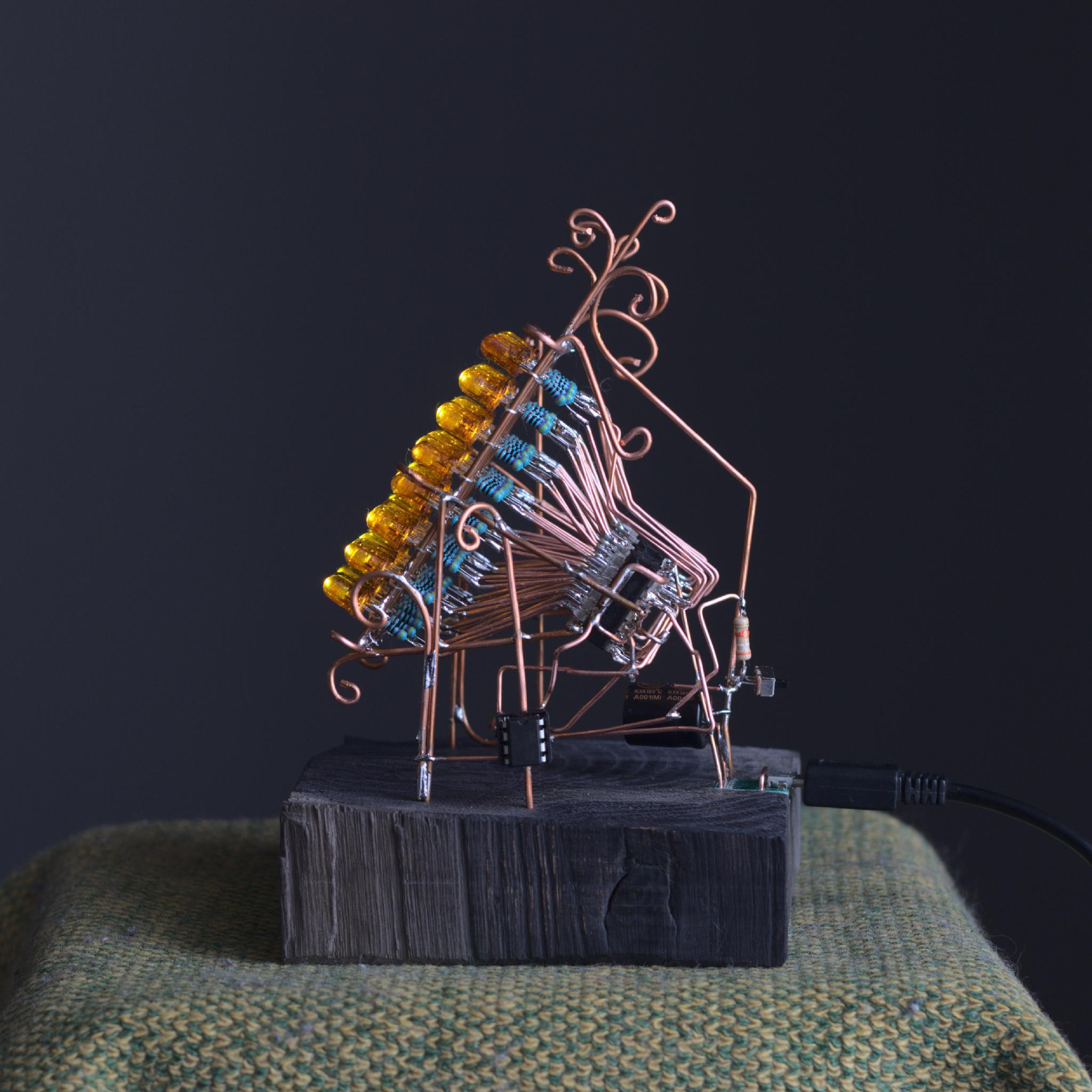
It has two modes: random flashy matrix and binary counter clock. It counts 64-bit number. You can calculate how many years it takes to reach the end. So, I think, that it is better to call it God's clock.
The LEDs was originally clear transparent. I used glass colours to paint them. Diffused yellow LEDs would be best to use.
Random mode:
#include <Arduino.h>
#include <avr/io.h>
#include <util/delay.h>
/*******************************
 *
 * Tauno Erik
 * 02.05.2020
 *
 ATtiny13-----------------------------------
 NC        PB5 - 1 U 8 - +5V
 KEY0 ADC3 PB3 - 2   7 - PB2 ADC1 NC
 KEY1 ADC4 PB4 - 3   6 - PB1 OC0B LAMP PWM2
           GND - 4___5 - PB0 OC0A LAMP PWM1
 74HC595------------------------------------
  Q1 - 1 u 16 - VCC
  Q2 - 2   15 - Q0
  Q3 - 3   14 - DS Serial DATA input
  Q4 - 4   13 - OE Output enable (Active low - conect to GND)
  Q5 - 5   12 - ST_CP Storage register clock pin - LATCH pin
  Q6 - 6   11 - SH_CP Shift Register CLOCK Pin
  Q7 - 7   10 - MR Master Reset (Actice low - it resets when low, keep it high)
 GND - 8___9  - Serial Out
 Circuit: ATtiny13 controlling a 8*74HC595 hooked to 8 LED's with 470ohm resistors
 ********************************/

/* Pins */
const uint8_t DATA_PIN =  4;
const uint8_t CLOCK_PIN = 3;
const uint8_t LATCH_PIN = 2;
const uint8_t BUTTON_PIN = 1;

/* */
const uint8_t NUM_OF_SR = 8;
uint8_t rows[NUM_OF_SR]{0}; // 8
uint8_t prev = 0;


/************************************************************/
void shiftOut(int myDataPin, int myClockPin, byte myDataOut)
{
  int i = 0;
  int pinState = 0;

//clear everything out just in case to
//prepare shift register for bit shifting
  digitalWrite(myDataPin, 0);
  digitalWrite(myClockPin, 0);

  for (i=7; i>=0; i--)  {
    digitalWrite(myClockPin, 0);

    //if the value passed to myDataOut and a bitmask result
    // true then... so if we are at i=6 and our value is
    // %11010100 it would the code compares it to %01000000
    // and proceeds to set pinState to 1.
    if ( myDataOut & (1<<i) ) {
      pinState= 1;
    }
    else {
      pinState= 0;
    }

    digitalWrite(myDataPin, pinState);
    digitalWrite(myClockPin, 1);
    digitalWrite(myDataPin, 0);
  }

  digitalWrite(myClockPin, 0); // stop shifting
}

/***************************************/
void binary_counter(uint8_t delay_time)
{

  for (uint8_t i = 0; i < NUM_OF_SR; i++)
  {
    prev = rows[i];
    if (prev == 255){
      rows[i] = 0;
    }
    else{
      rows[i]++;
      i = 8;
    }
  }

  digitalWrite(LATCH_PIN, 0);
  for (uint8_t k = NUM_OF_SR; k > 0; k--)
  {
    shiftOut(DATA_PIN, CLOCK_PIN, rows[k-1]);
  }
  digitalWrite(LATCH_PIN, 1);
  delay(delay_time);
}

/************************************************************/

void random_generator(uint8_t delay_time)
{
  for (uint8_t i = 0; i < NUM_OF_SR; i++)
  {
    rows[i] = random(255);
  }

  digitalWrite(LATCH_PIN, 0);
  for (uint8_t k = NUM_OF_SR; k > 0; k--)
  {
    shiftOut(DATA_PIN, CLOCK_PIN, rows[k-1]);
  }
  digitalWrite(LATCH_PIN, 1);
  delay(delay_time);
}

/************************************************************/

int main(void)
{
  pinMode(LATCH_PIN, OUTPUT);
  pinMode(CLOCK_PIN, OUTPUT);
  pinMode(DATA_PIN, OUTPUT);
  pinMode(BUTTON_PIN, INPUT);

  // if analog input pin 0 is unconnected, random analog
  // noise will cause the call to randomSeed() to generate
  // different seed numbers each time the sketch runs.
  // randomSeed() will then shuffle the random function.
  randomSeed(analogRead(0));

  while (1)
  {
    //read pin PB1
    if (PINB & (1<<BUTTON_PIN)) // Low
    {
      random_generator(100);
    }
    else // High
    {
      binary_counter(10);
    }


  }

  return 0;
}


 Lee Sampson
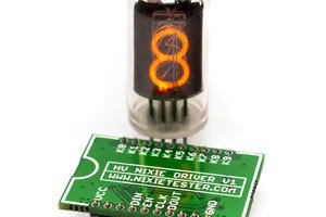
 Marcin Saj
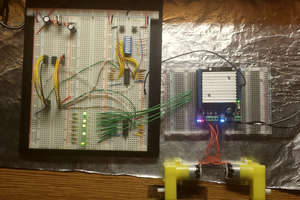
 sercanca.com
quirky little project!! I have a lot of HE yellow/orange LEDs to use up..this could be just the thing!