 David Wilson
Motivation
The Arduino single-board microcontroller (https://www.arduino.cc) and its spinoffs have opened up a world of opportunities for makers, educators, and researchers. Intended for classroom and lab prototypes, these boards are generally not designed to be used in a remote setting. So the powering options are limited to a USB cable or a 7-12V wall adapter.
The Adafruit Feather family (https://learn.adafruit.com/category/feather) partly remedies this by offering a JST power supply connector for a lithium ion polymer (LiPo) battery (https://www.adafruit.com/product/1570), and a built-in recharger . One downside, however, is the lack of support for standard disposable batteries such as AA, C, D, or 9V alkalines. There are several reasons one would want to use these batteries. LiPo batteries have known safety issues (https://en.wikipedia.org/wiki/Lithium-ion_battery#Safety) as well as limitations on their shipment and transport; in a field setting such as environmental monitoring, it can be more convenient to carry replacement batteries out to the installation than to recharge LiPo batteries; and disposable batteries have a lower initial cost than LiPo.
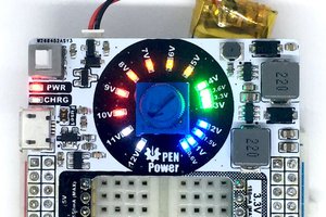
The present design is a board in the standard FeatherWing form factor (https://learn.adafruit.com/adafruit-feather/feather-specification) that is intended to fill this gap. This board has its own 2.1-mm barrel connector (compatible with many battery holders) that accepts a dc power input between 2V (3V to start up) and 15V. The buck-boost converter efficiently converts this input to a 3.3-V level that is output to the 3.3V pin of the Feather stack. As this is a switching converter, it will in most cases be more efficient than the standard LDO that is supplied with the Feather, resulting in longer battery life and more complete use of the battery capacity.
Design Details
Summary of features:
- Texas Instruments TPS63070 buck-boost switching converter.
- Adafruit Feather board size (0.9 in x 2.0 in) and pinout.
- 2.1-mm barrel connector for supply input.
- Input voltage range: 2V – 15V (3V required to start).
- Output current capability: TBD but at least 500mA.
- Power-save mode for low-load efficiency (default).
- Jumper option to force PWM mode for high-load efficiency.
- Slide switch to select switcher or LDO operation; unused regulator disabled.
- Reset pin.
- Battery monitor pin (optional).
- JST-PH connector as alternative
The TPS63070 switching converter can start operation at any input voltage from 3V to 15V; once started, the TPS63070 will continue to run down to 2V if the supply is not interrupted. In this way, a battery can be almost completely drained before discarding.
The TPS63070 is specified to output up to 2A; due to the current capability of the pins, however, no more than 500mA is recommended. The typical user will need much less than this.
This board shares the Feather pinout and, depending on the headers installed, can be stacked above or below the Feather board and any optional wings. It should not interfere with the function of any of the digital or analog pins.
The 3.3-V output from the converter is fed to the 3.3V pin to supply the Feather and any Wings in the stack. Due to the design of the Feather, this pin is also powered by the LDO regulator on the main board; in order to avoid having competing current sources, a SPDT slide switch is provided, by which the user selects which source is to supply the 3.3V. The unused source is disabled at the same time.
Low Power Mode: the converter is designed to be highly efficient, but in its standard PWM mode, the efficiency is optimized for a high-current regime. However, there is a power-saving mode that in enabled with a pin; this is the default of this design, but it can be overridden (PWM mode selected) by soldering across jumper pads JP4.
A resistor divider is provided for monitoring the input voltage. This is not connected by default, but soldering...
Read more »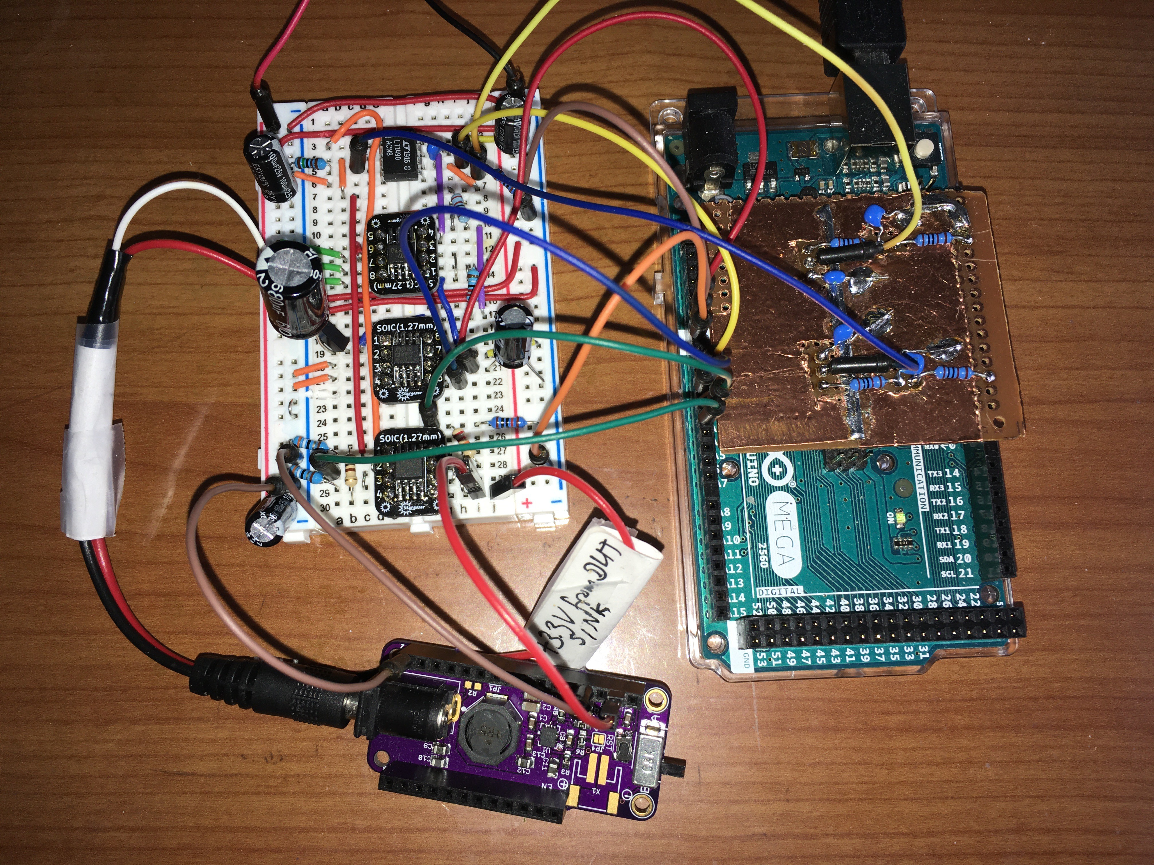 This fixture uses an Arduino Mega as a controller, only because my Arduino UNO was fried. I have some breadboard analog electronics to supply an input voltage and an output sink current to the device-under-test (DUT) under control of filtered PWM outputs from the Mega. Then I use the Mega's analog inputs to read the DUT's input current and output voltage. The program can do a sweep over ranges of voltage and current and report the results in a table. The power supply for the test fixture is a cheap unregulated 15-volt AC-DC wall-wart. I can supply more details if requested.
 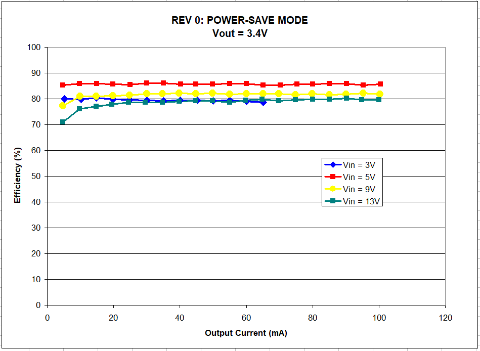 The improved Rev 1 design is also shown in power-save mode. Note the efficiency improvement, and that the device can be operated down to about 10mA without any dropoff in efficiency:
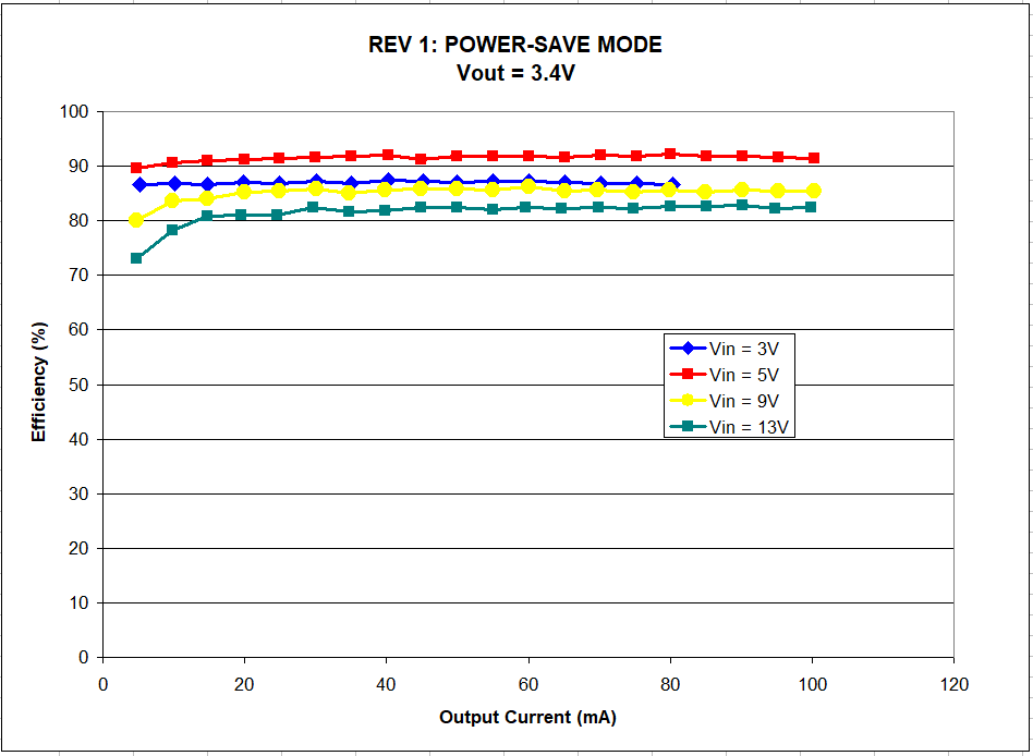 For comparison, here is the result of testing a Rev 0 board in PWM mode; my fixture is limited to 100mA input or output current, but you can see that the peak efficiency now does not happen in this range:
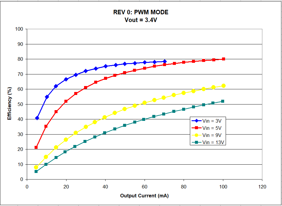 For comparison, I will also show a couple of charts from the datasheet, although the examples show the device operating with 5-V output. The efficiency in power-save mode:
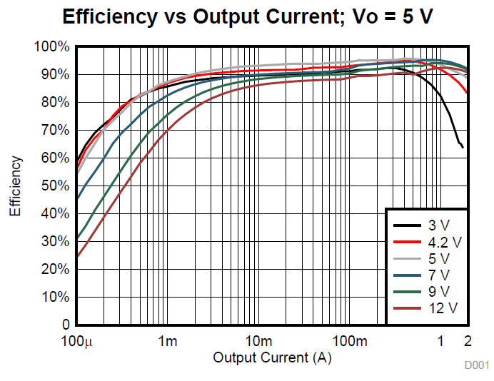 And the efficiency in PWM mode; note that the peak efficiency is slightly higher than that of the power-save mode, but not until output current reaches a few hundred mA:
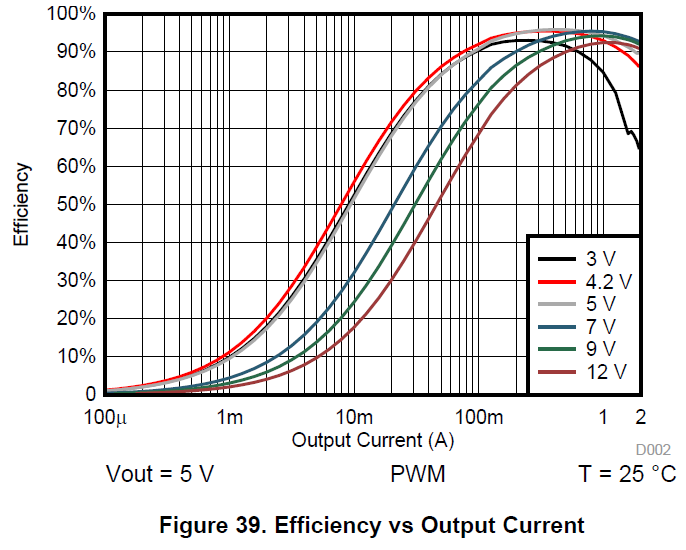
 Nathaniel VerLee
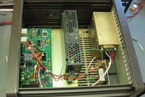
 Quinn
Quinn
 John Loeffler