 Kevin Santo Cappuccio
breadWare v0.2
My reason for doing this whole writeup and putting this out there is to hopefully find some fellow hackers who are equally stoked on breadWare and want to help make it into something where people will wonder how the hell they built anything before it existed (probably not Arduino levels of disruption, but when I need to use a Bus Pirate, I can't even imagine the horrible dystopian hellscape the world would be without it.) At least for me, placing jumpers messes up my flow, because there's always that angel on one shoulder telling me to be methodical: cut my jumpers to the right length, make nice 90° bends, use colors consistently, while the demon on the other shoulder says to just get the damn thing working now and let future me deal with the mess. The demon always wins, so I'd really like the angel to shut up, it's distracting. So offloading that internal debate to a computer seems like a good idea [disclaimer: do not run this on a HAL 9000 computer, I hear cognitive dissonance like this can cause undefined behavior]

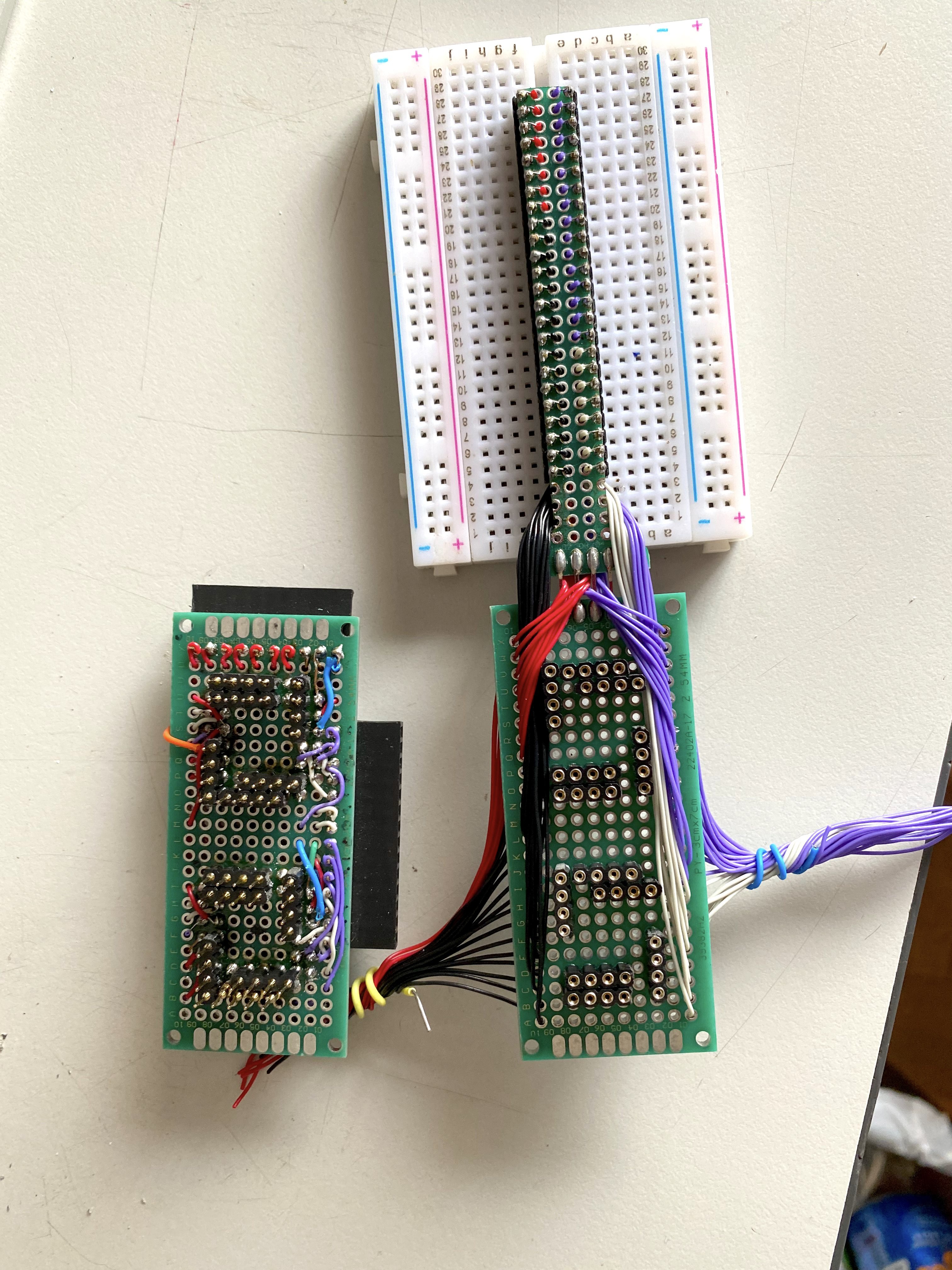
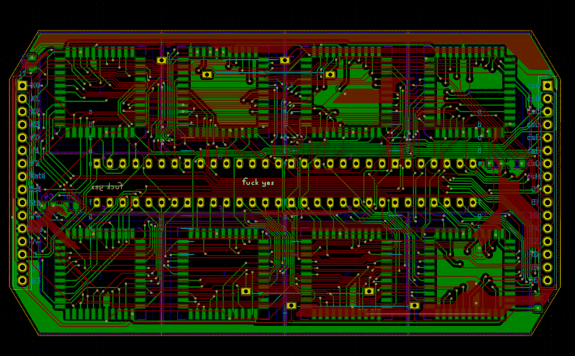
Here’s the second board revision. I was showing off the last version to someone and they offhandedly mentioned that it would be cool if the whole thing fit under the breadboard. I knew this was my plan all along, but it forced me to finally design it before the code gets too specific to the original off-the-cuff design and I get stuck with my poor life design choices.
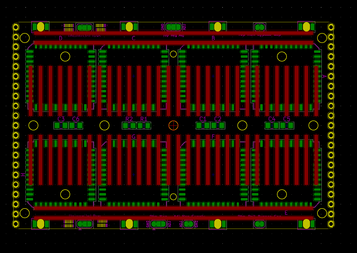
Matrix Board Changes


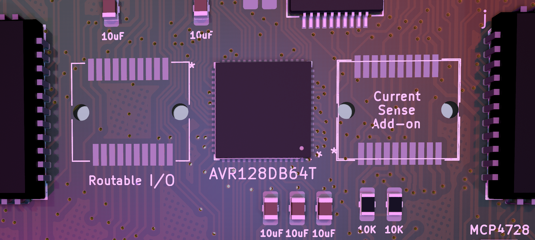
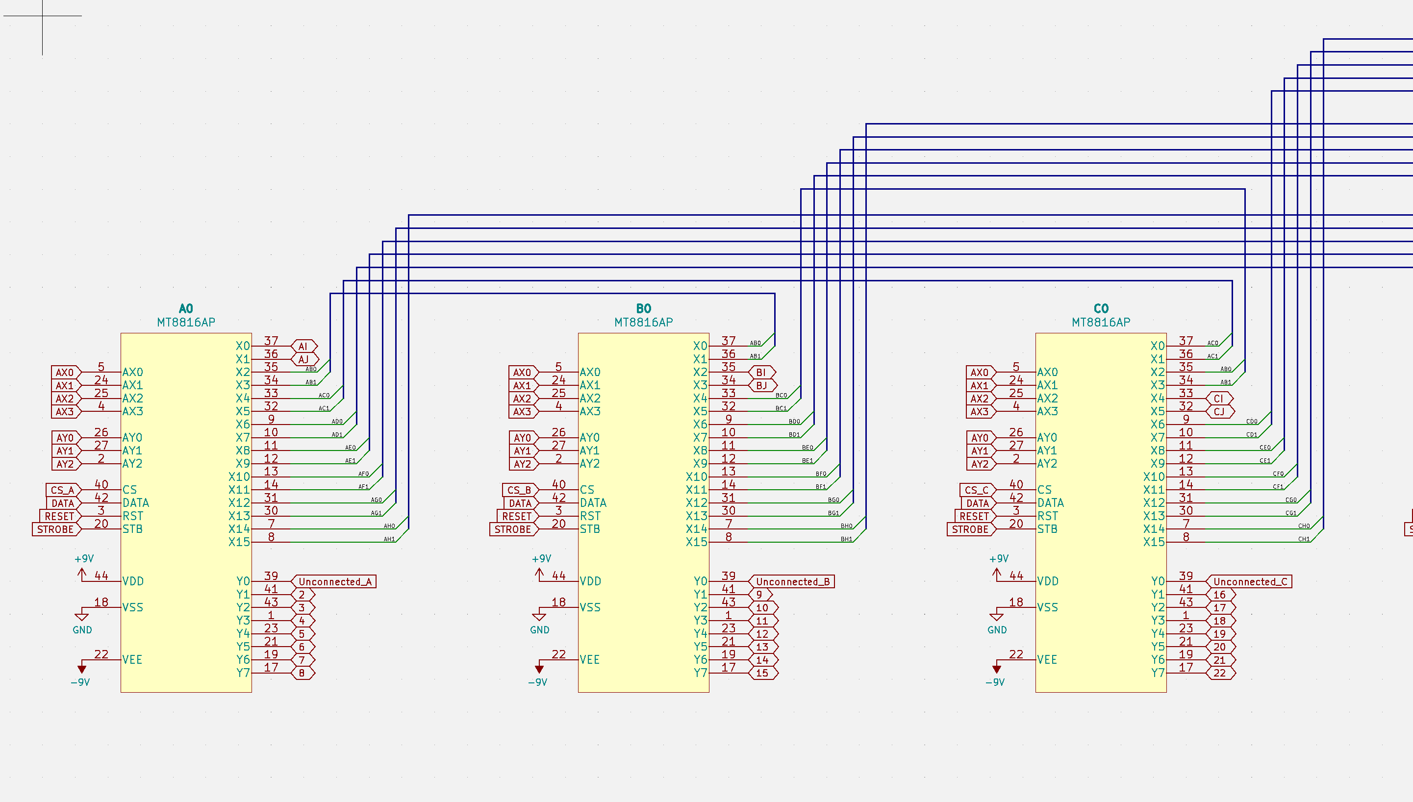
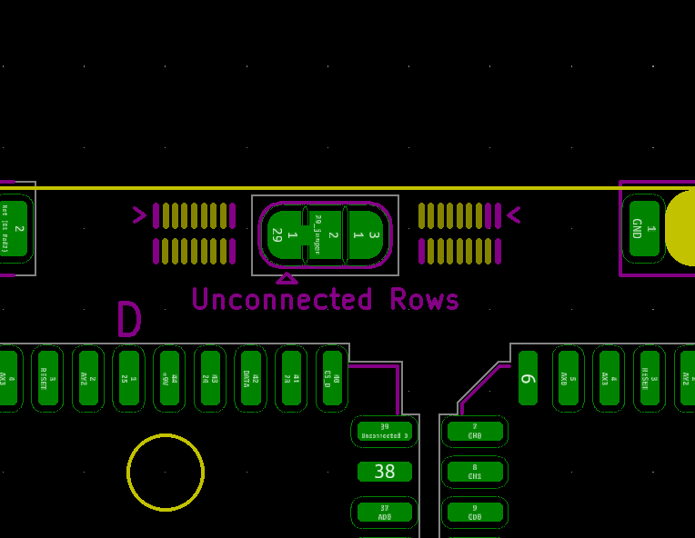
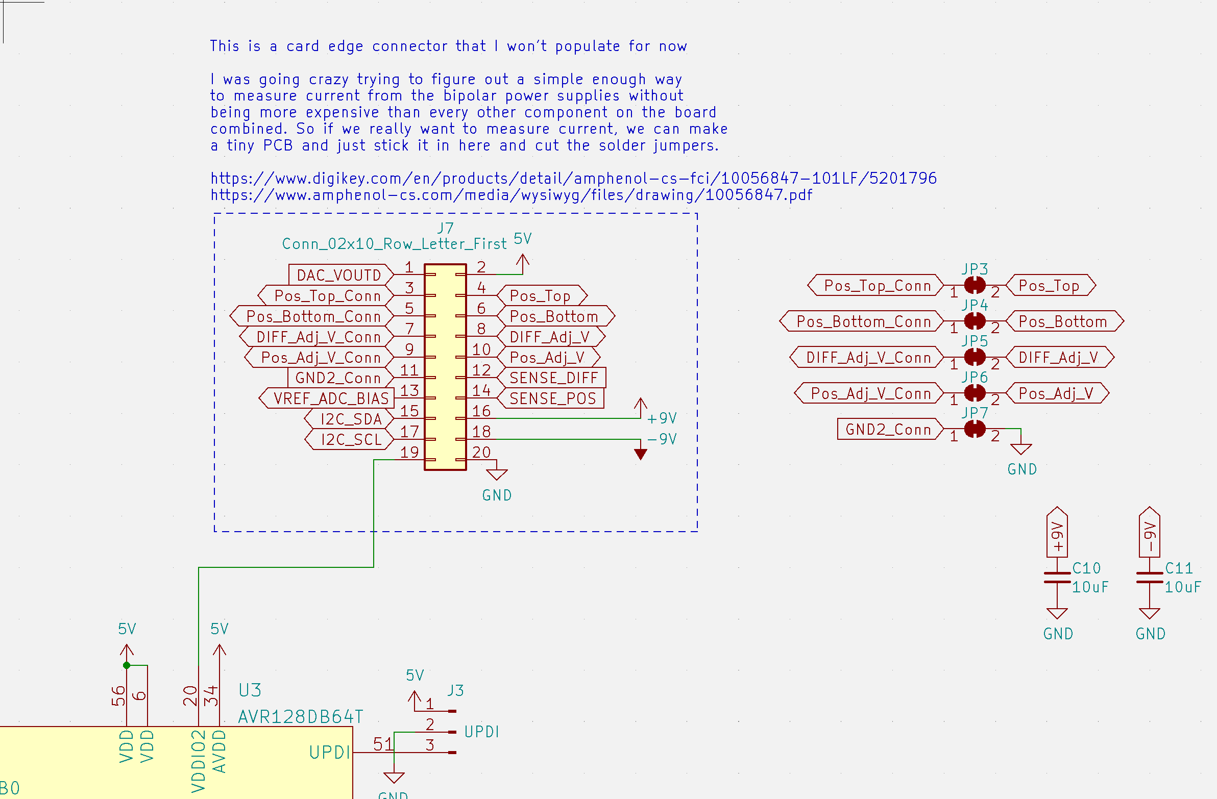
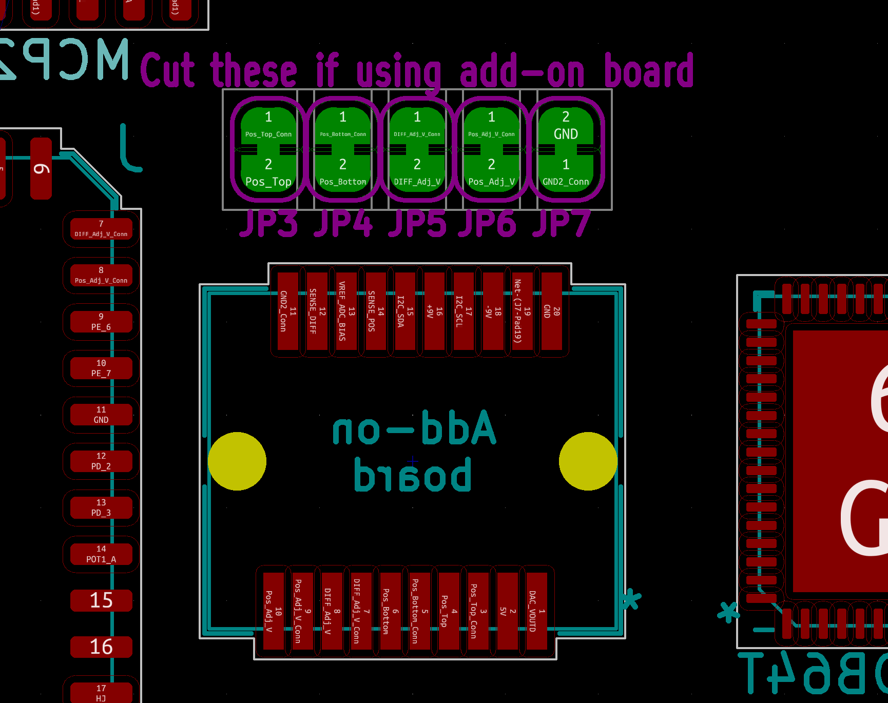
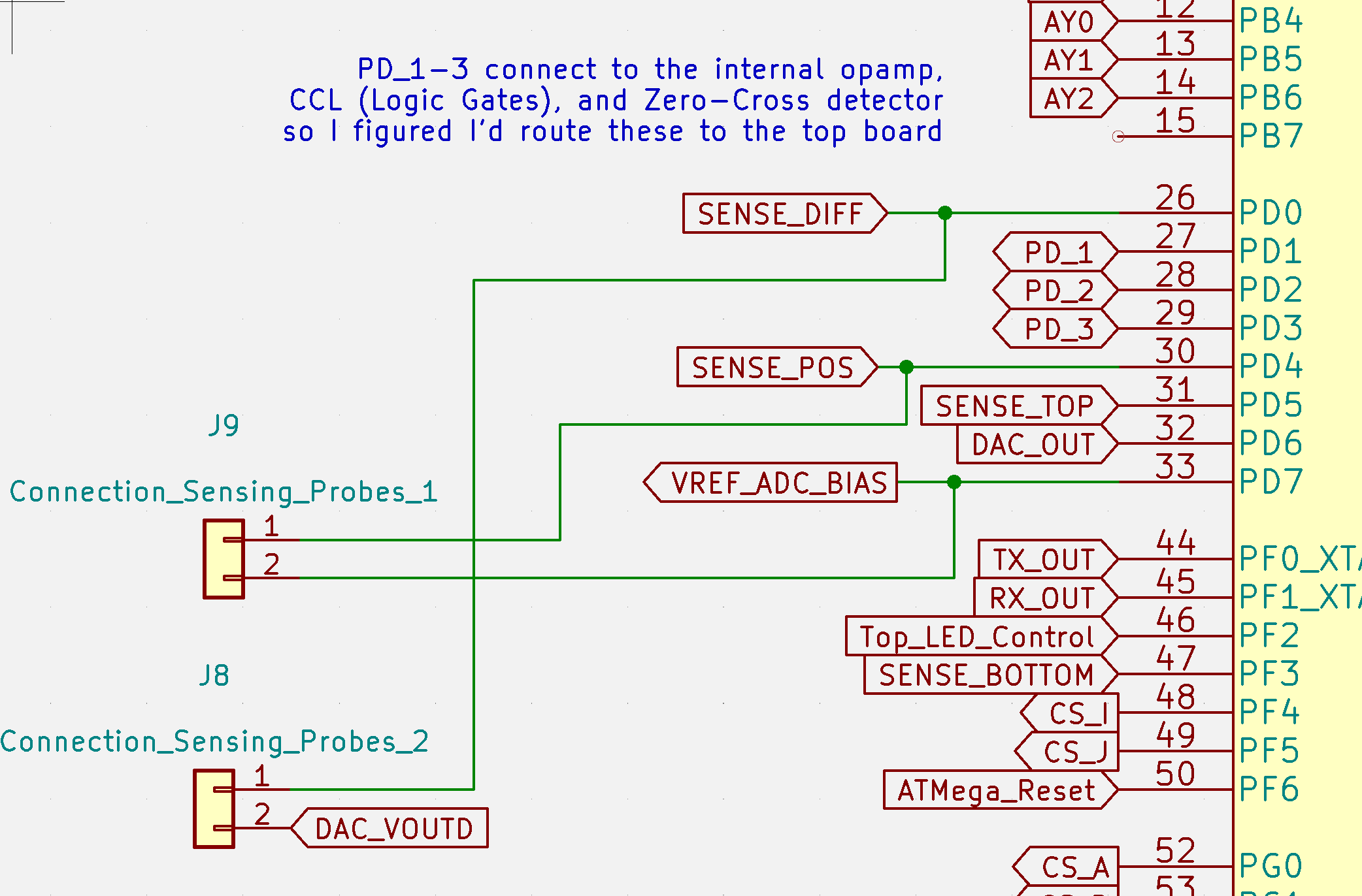
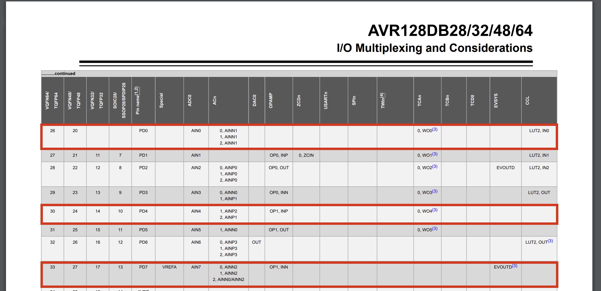
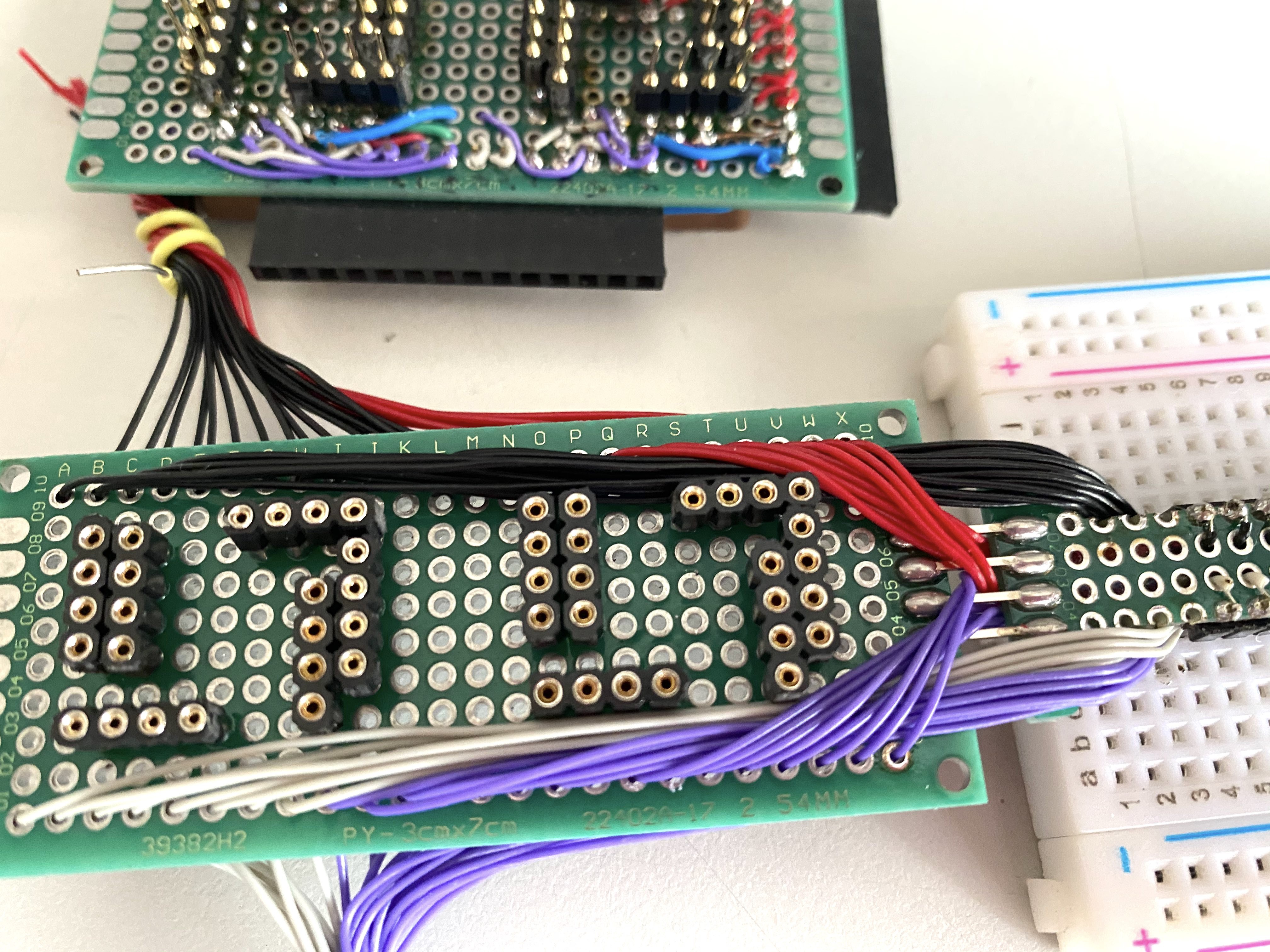
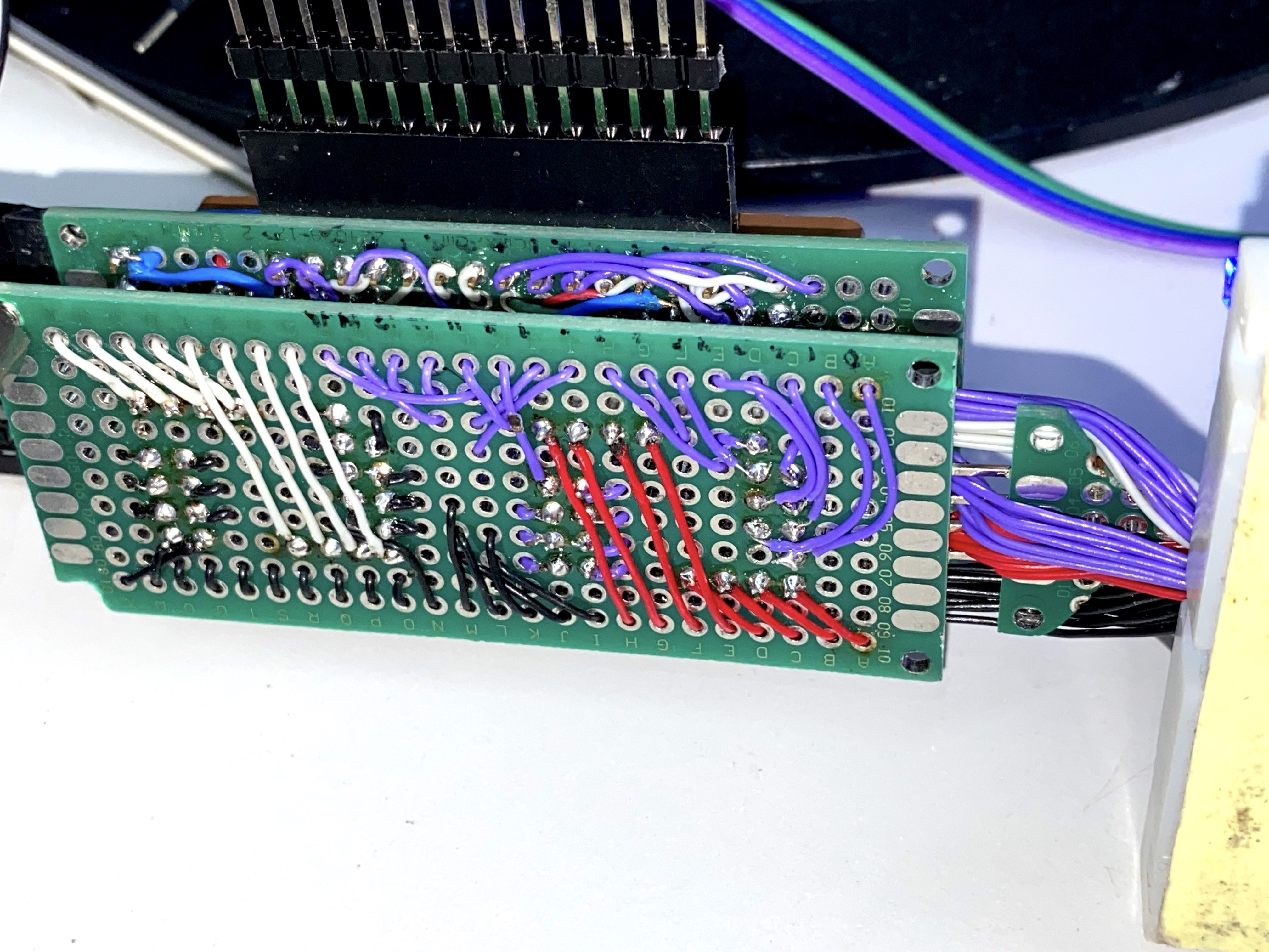
I found that the most valuable resource when finding paths between rows that aren’t directly connected (so they need to make an intermediate hop) are “virtual” breadboard rows that aren’t connected to the actual board but connect to the control board below and basically act as the general purpose nodes to do everything else (like reading voltages, connecting to the GPIO on the microcontroller, connecting to a second board, etc.). I put 4 of them in (on chips A, D, E, H), and I don’t think that’s nearly enough if I want to be able to do a bunch of special function things at once without making the user use some particular set of rows to do certain things. I would really like to make it as simple as “put anything wherever and the board will figure it out.”
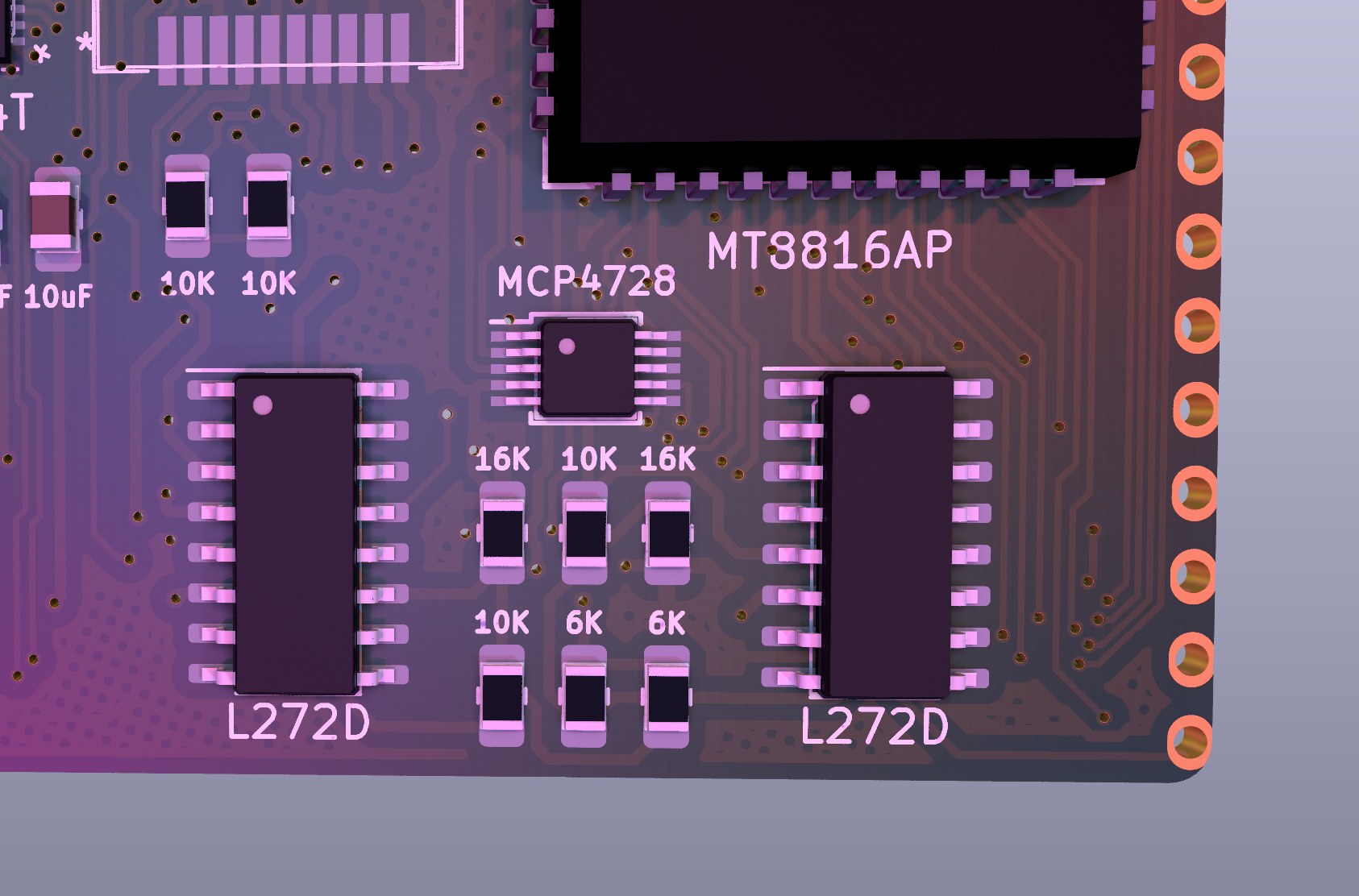
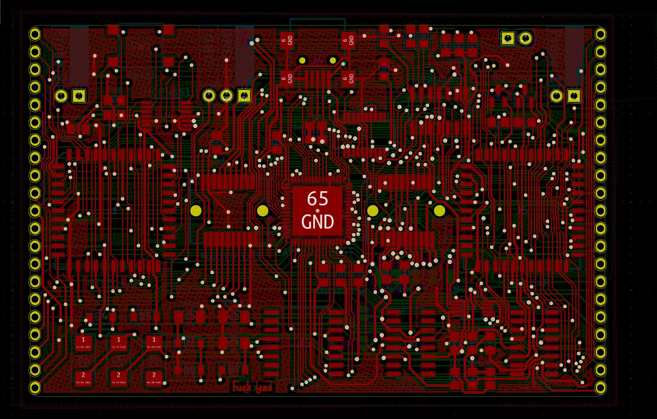
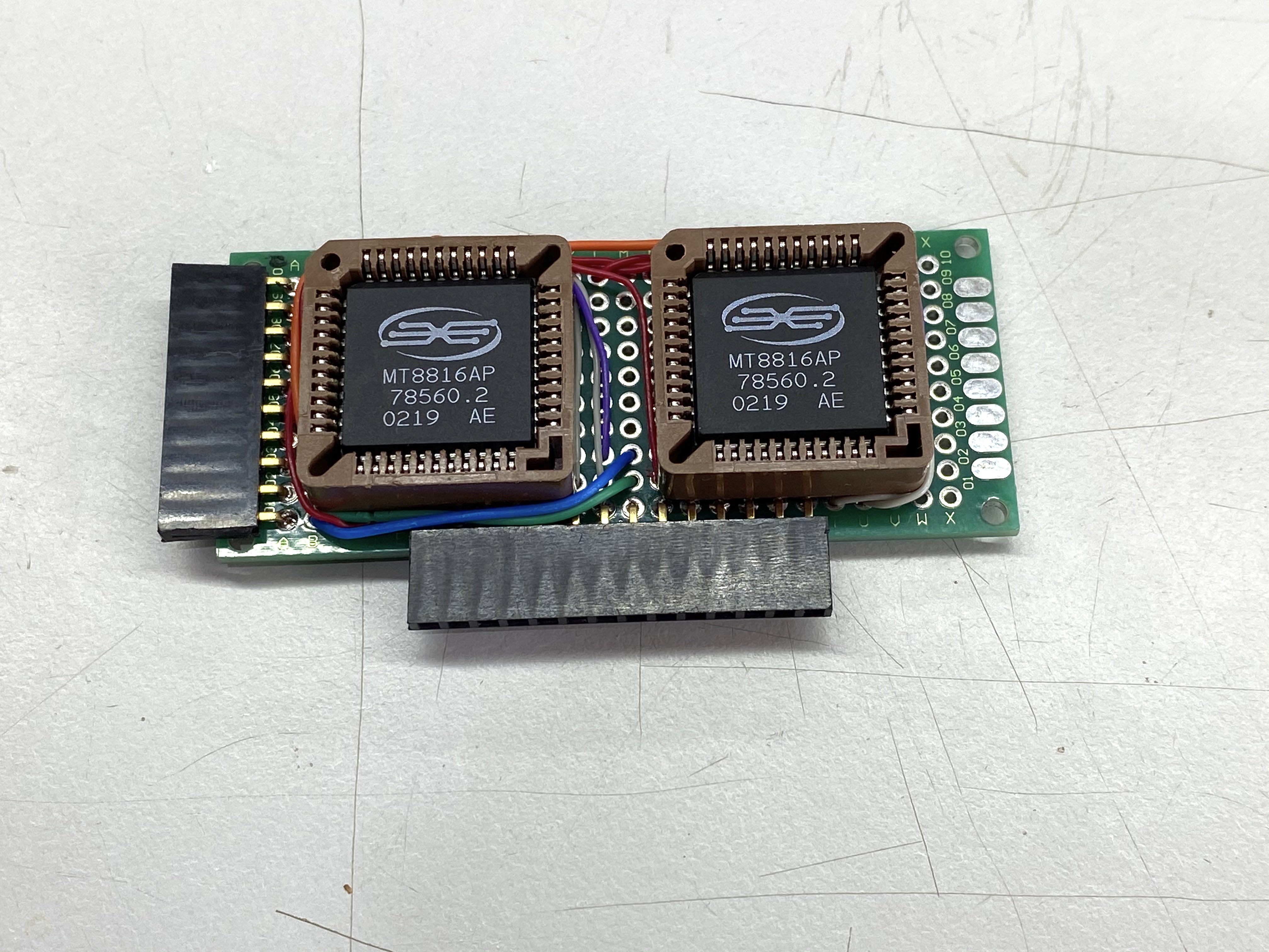
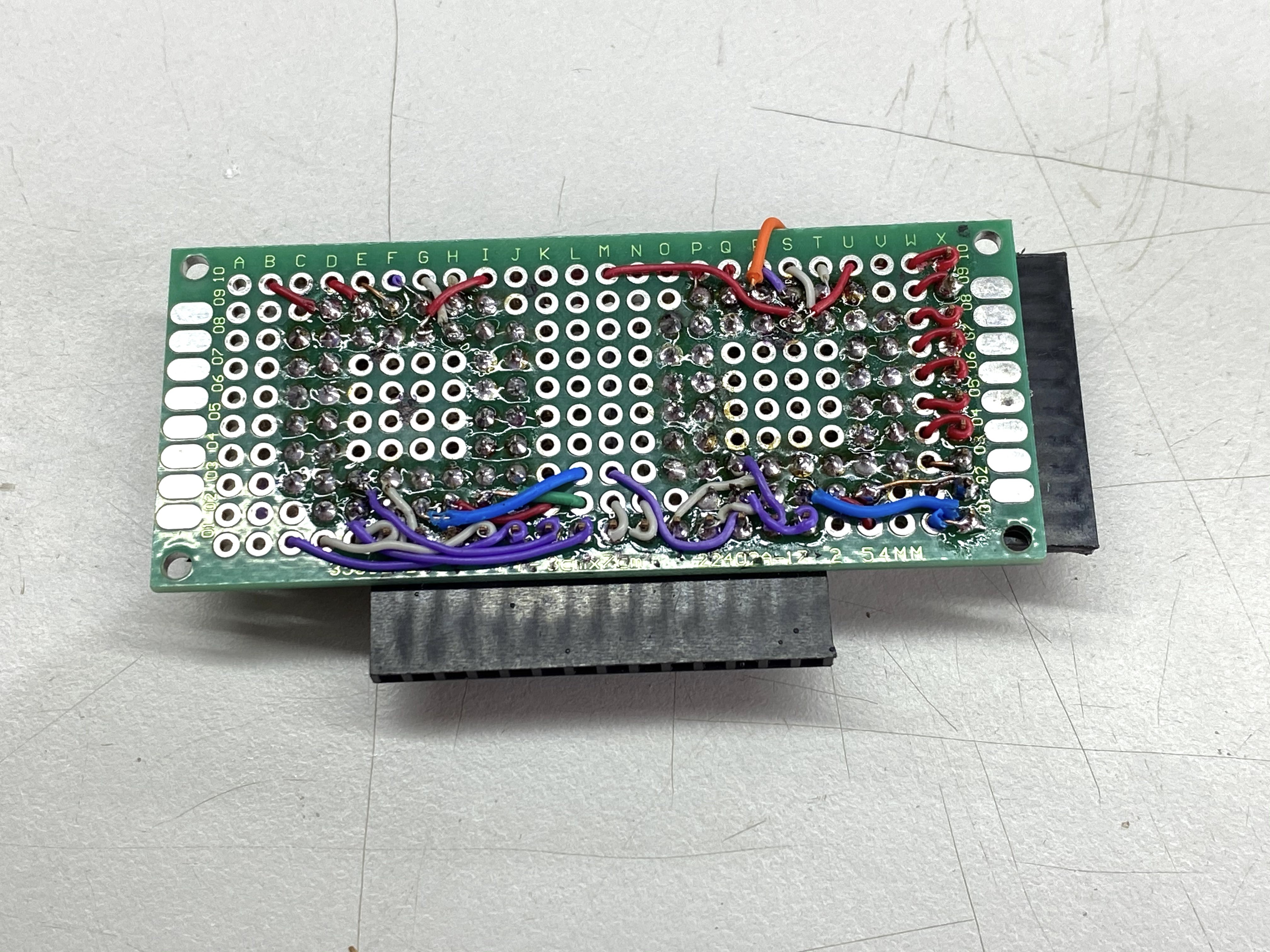
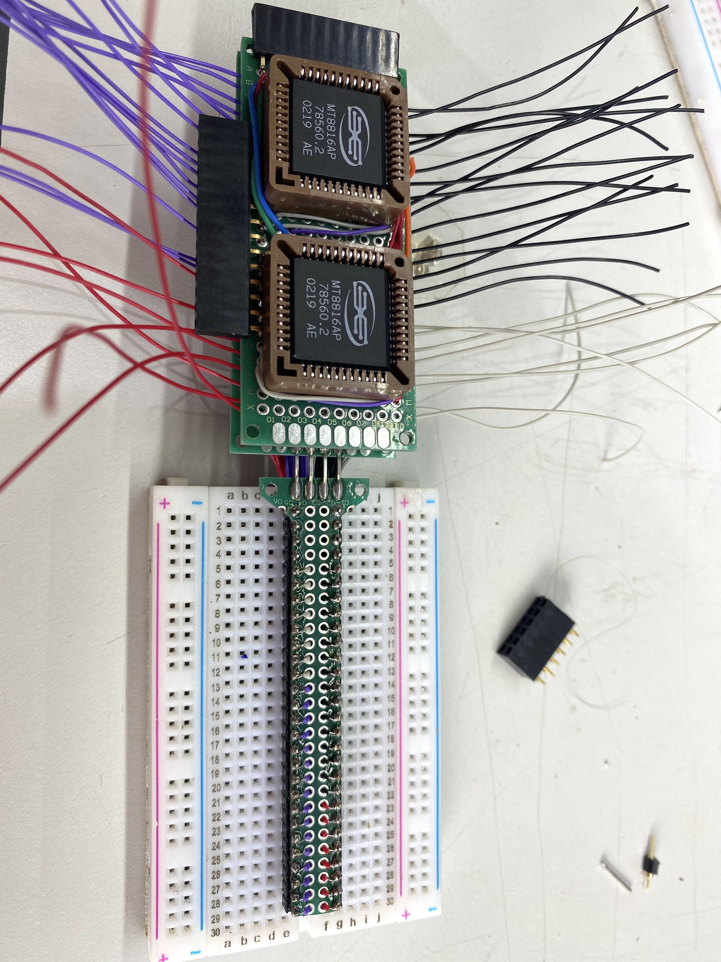
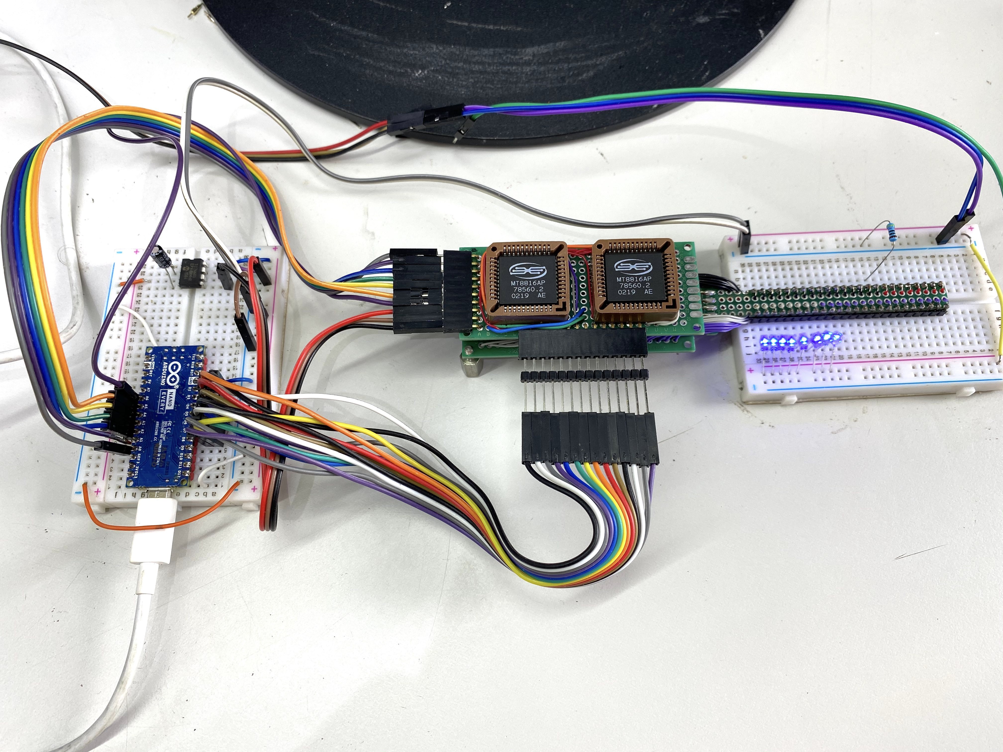
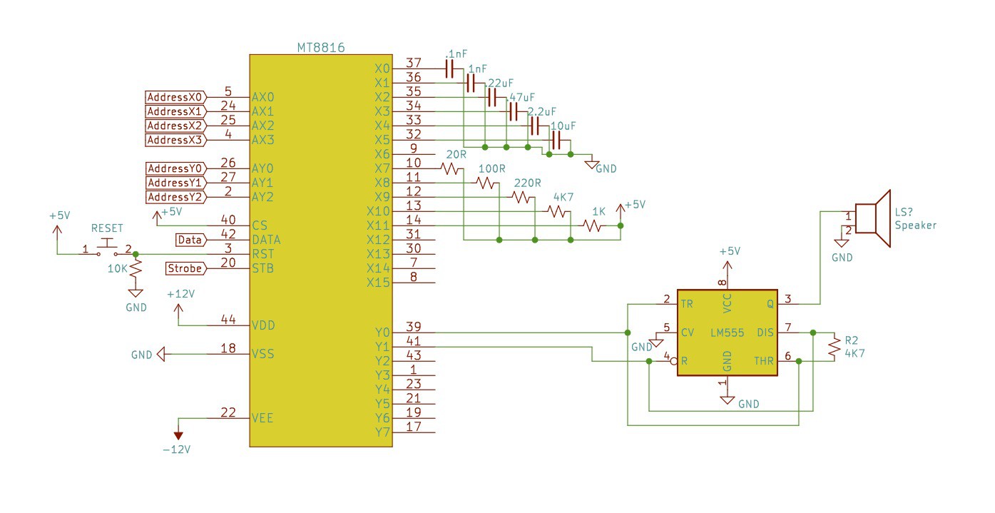
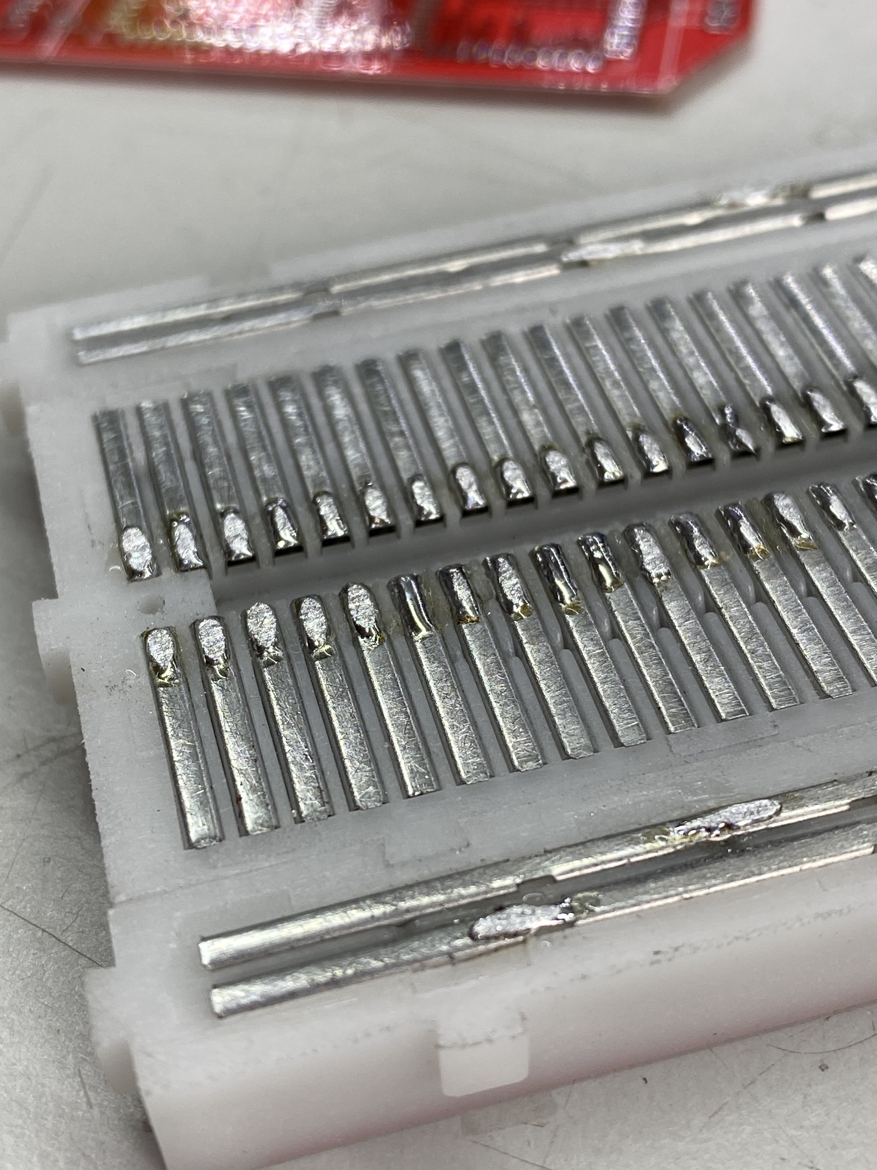
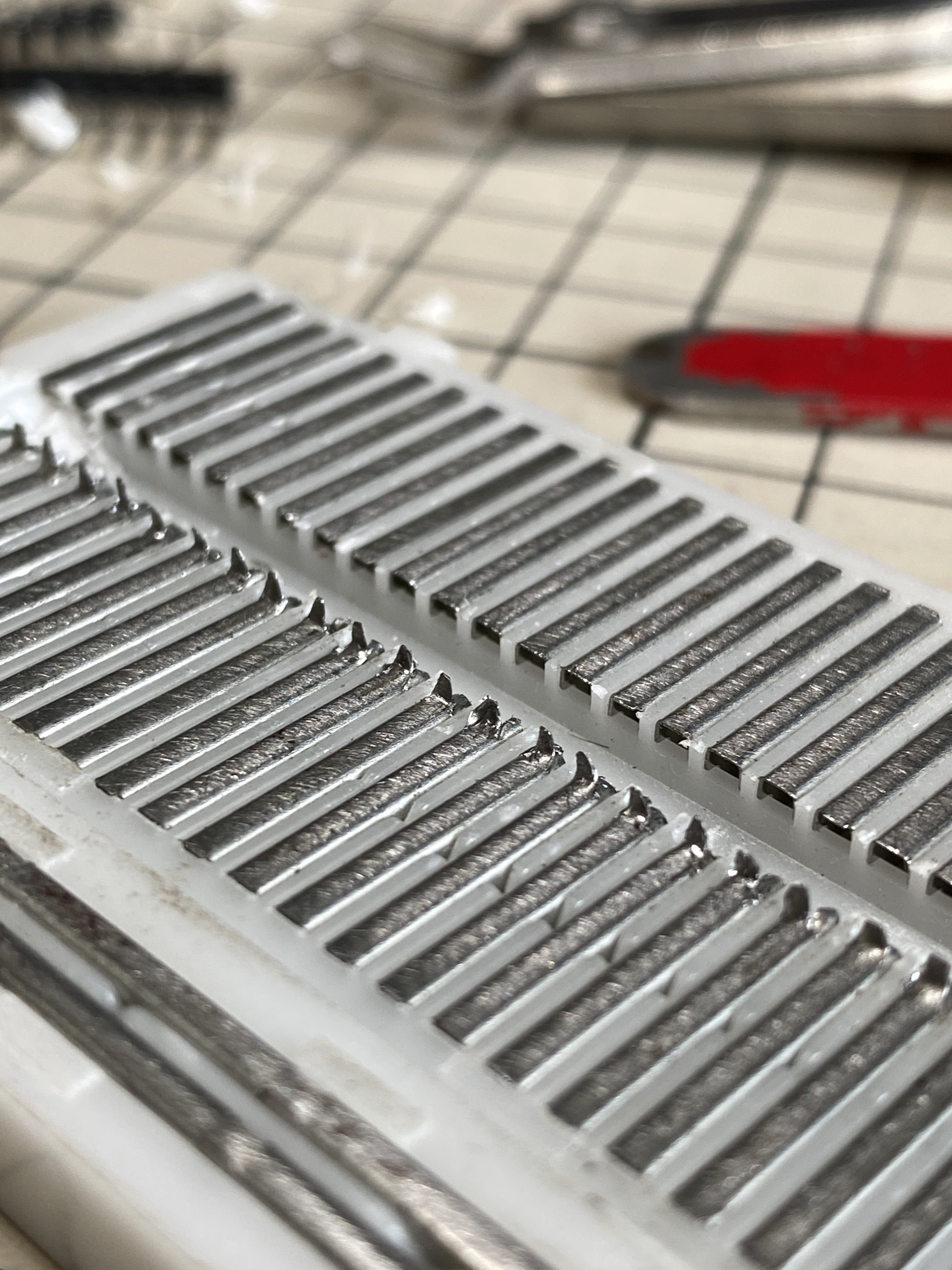
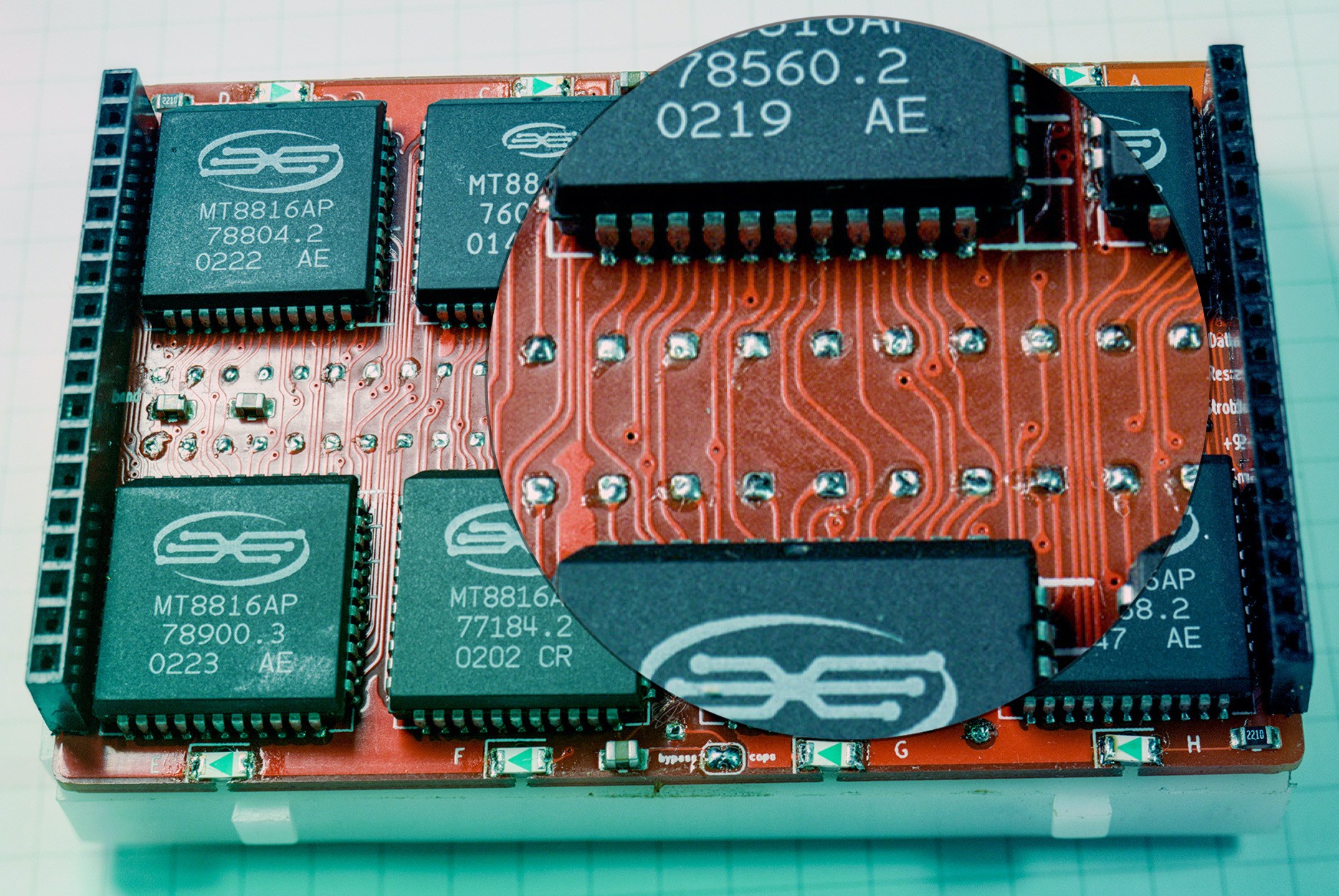
I changed the logical arrangement of the MT8816 crosspoint switches to make the it easier to just hop over the middle space. In the original layout if I wanted to connect top row 5 to bottom row 5, it would always take 2 hops to do that (and these switches each have an on resistance of about 65Ω). Now the bottom rows are flipped so internally the bottom left is 62 and counts down to 33 on the right (note: these are abstracted away to the user by using b1-b30 instead of bigger numbers.)
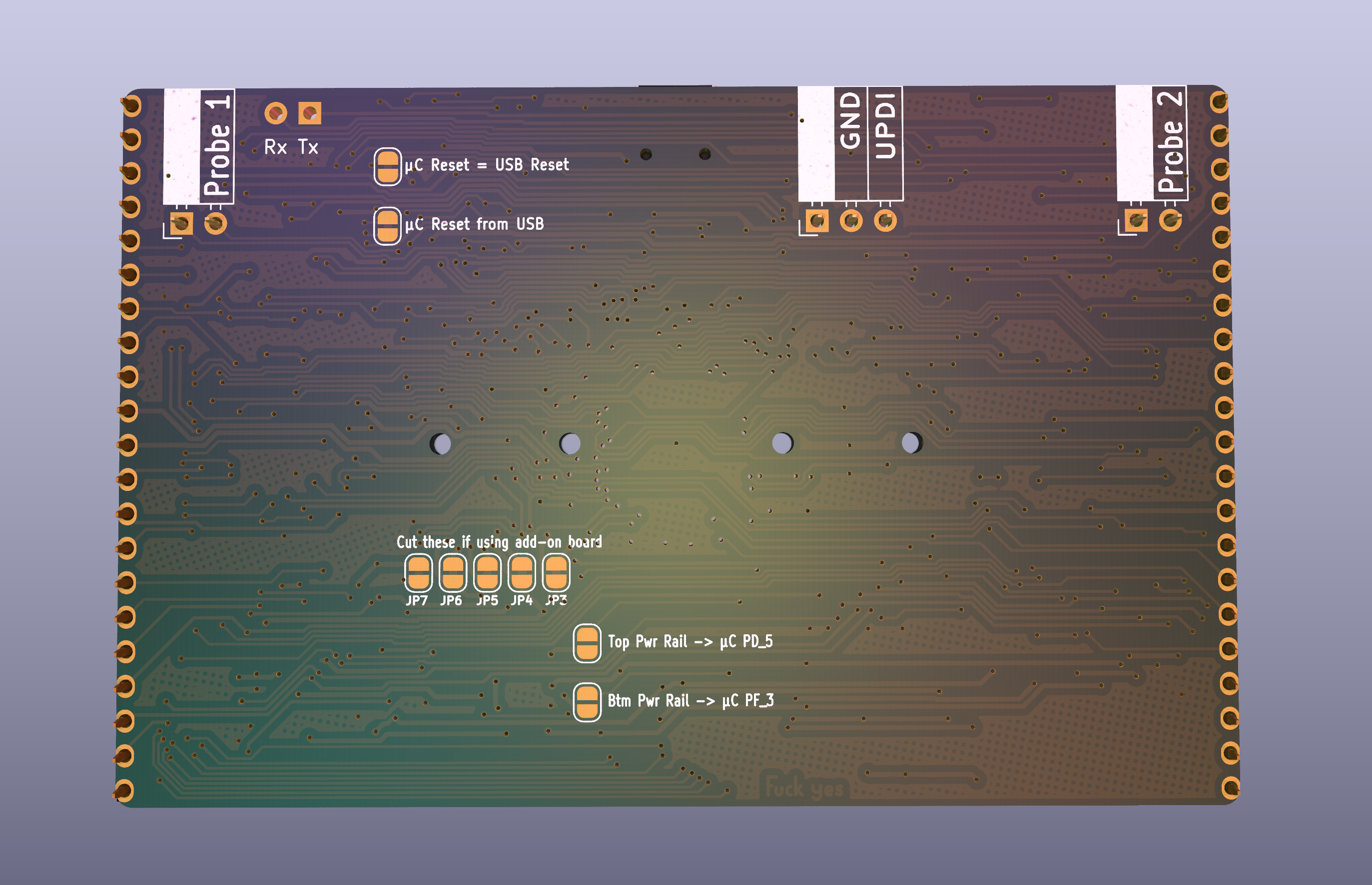
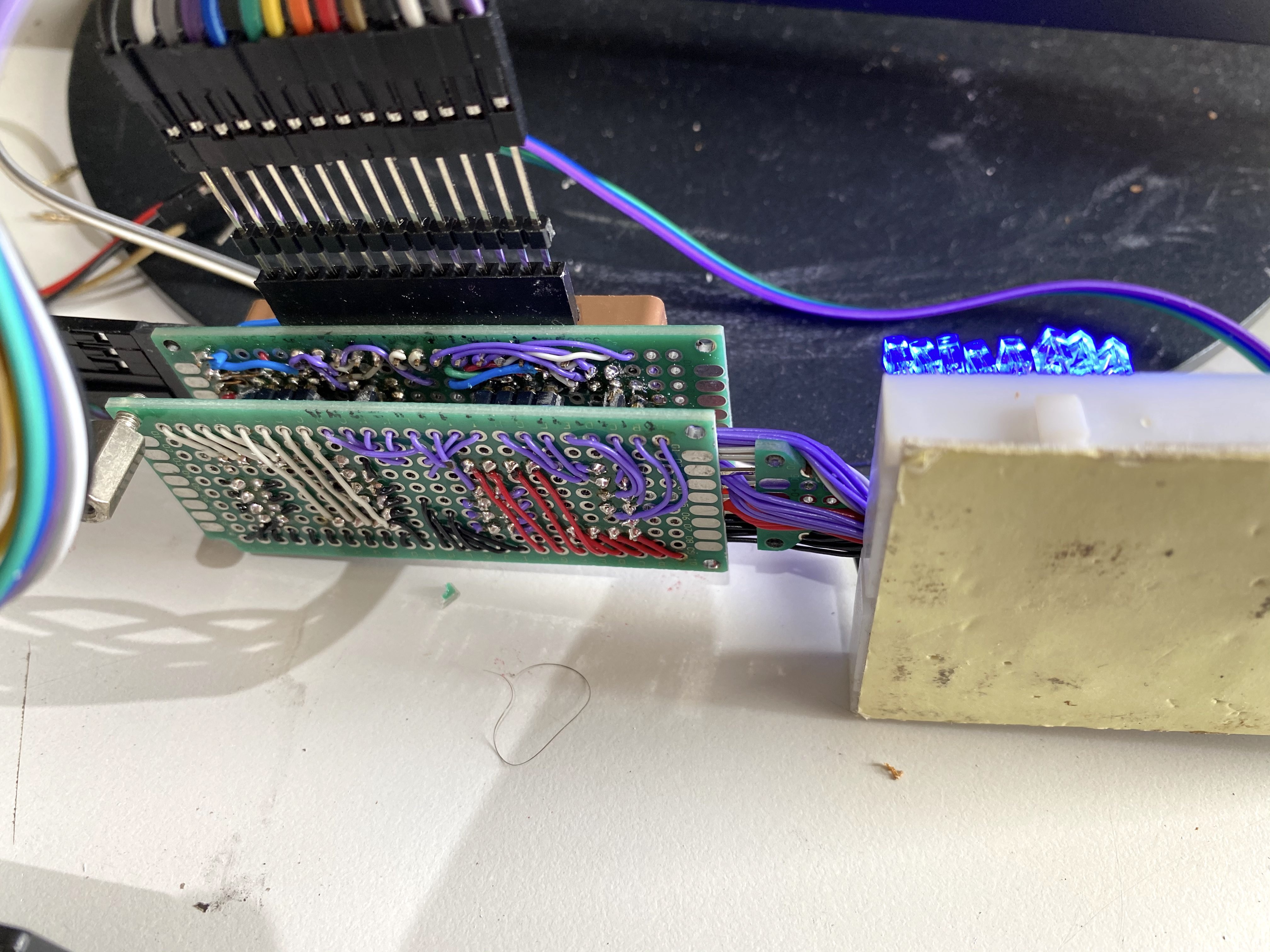
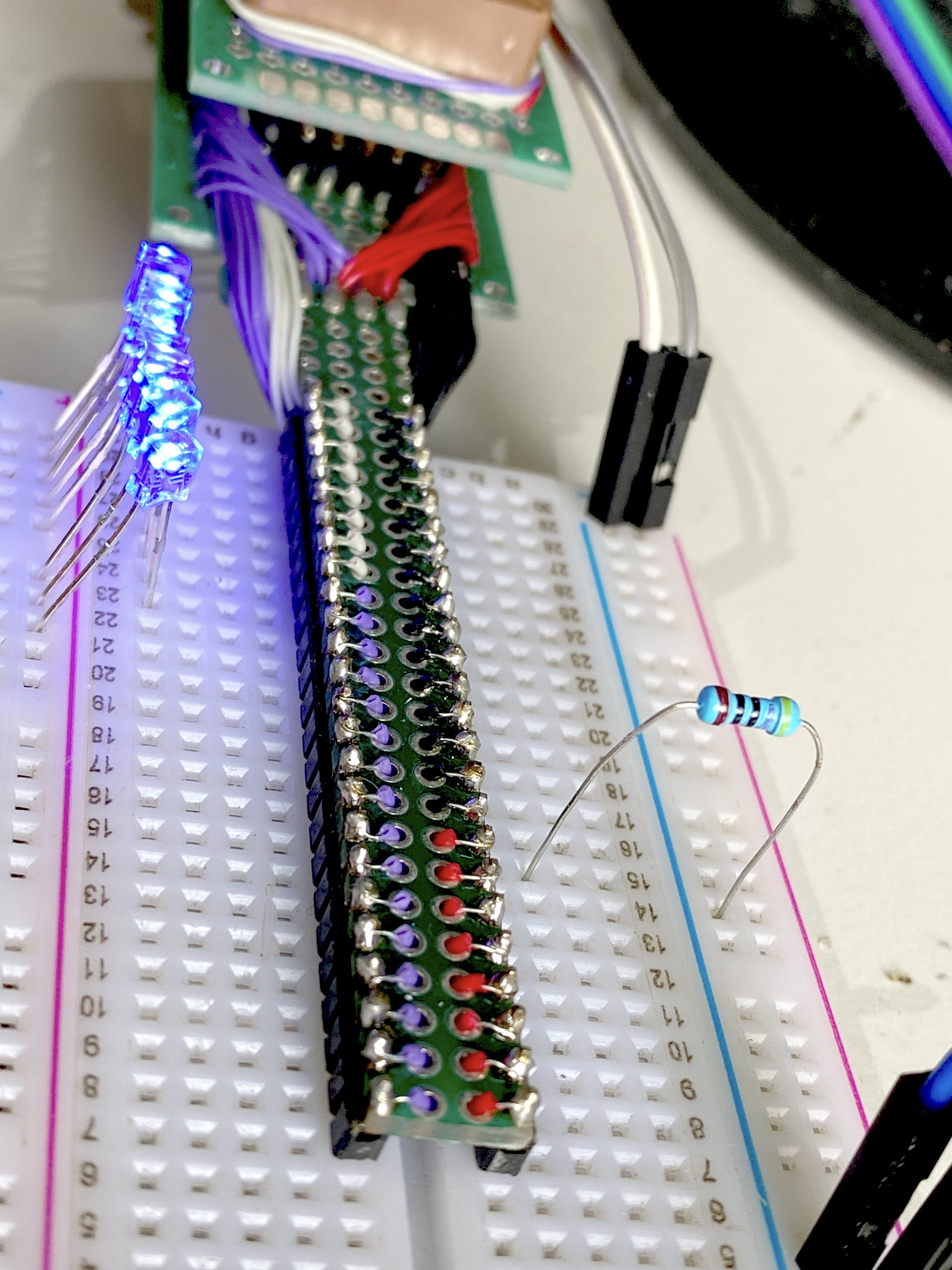
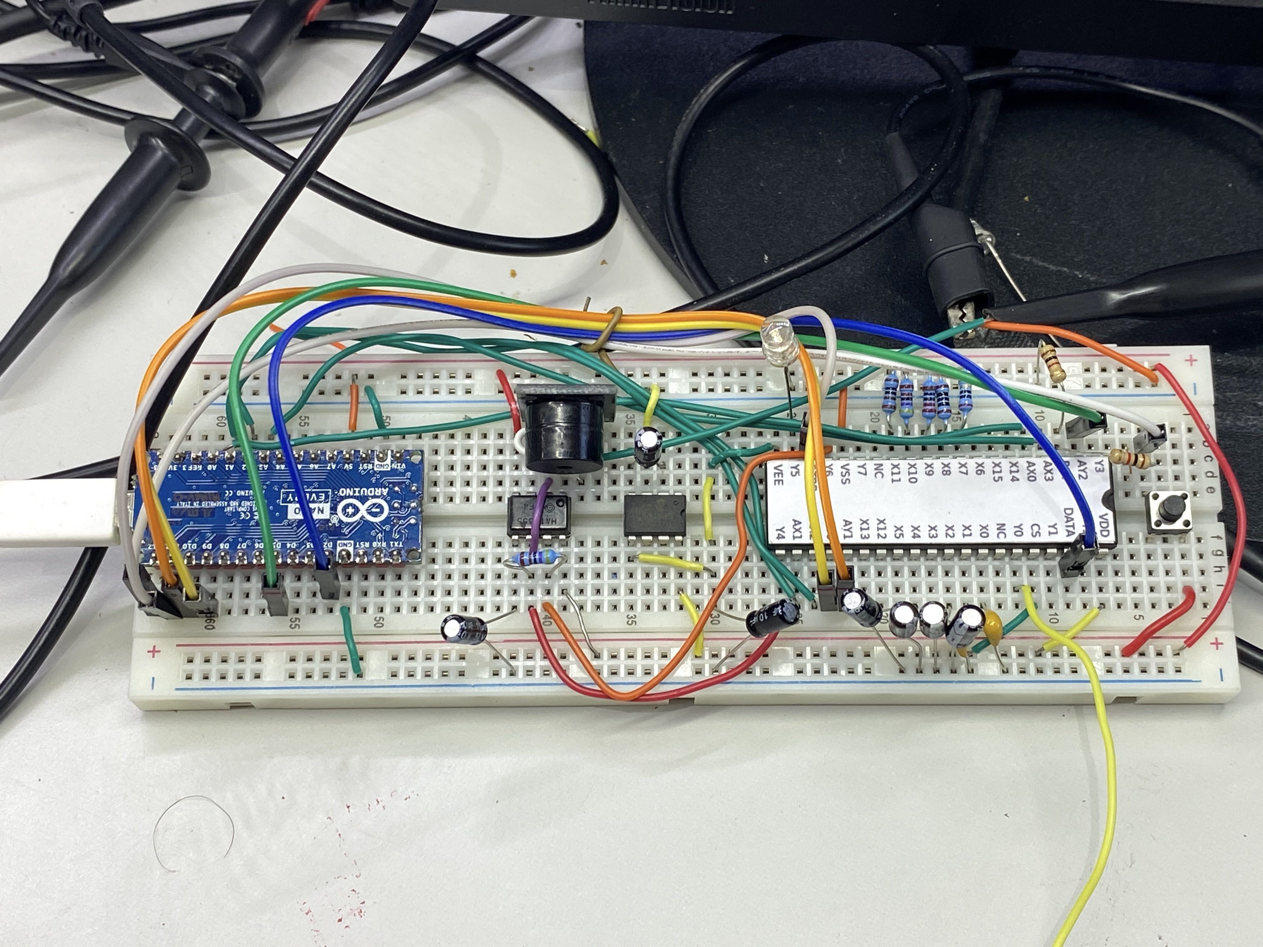
And just to add some glam I added some reverse mounted LEDs that shine through the top and bottom power rails to show when that rail’s power supply is on.
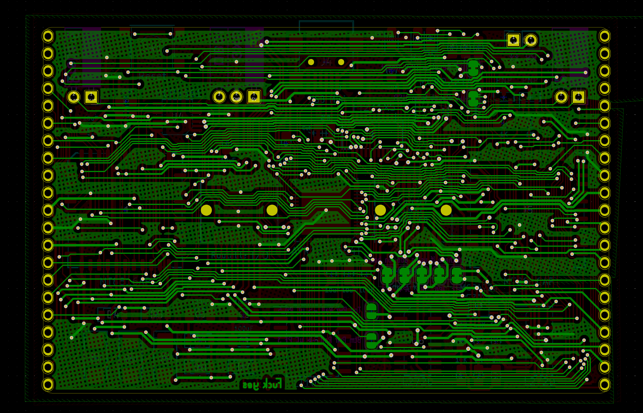
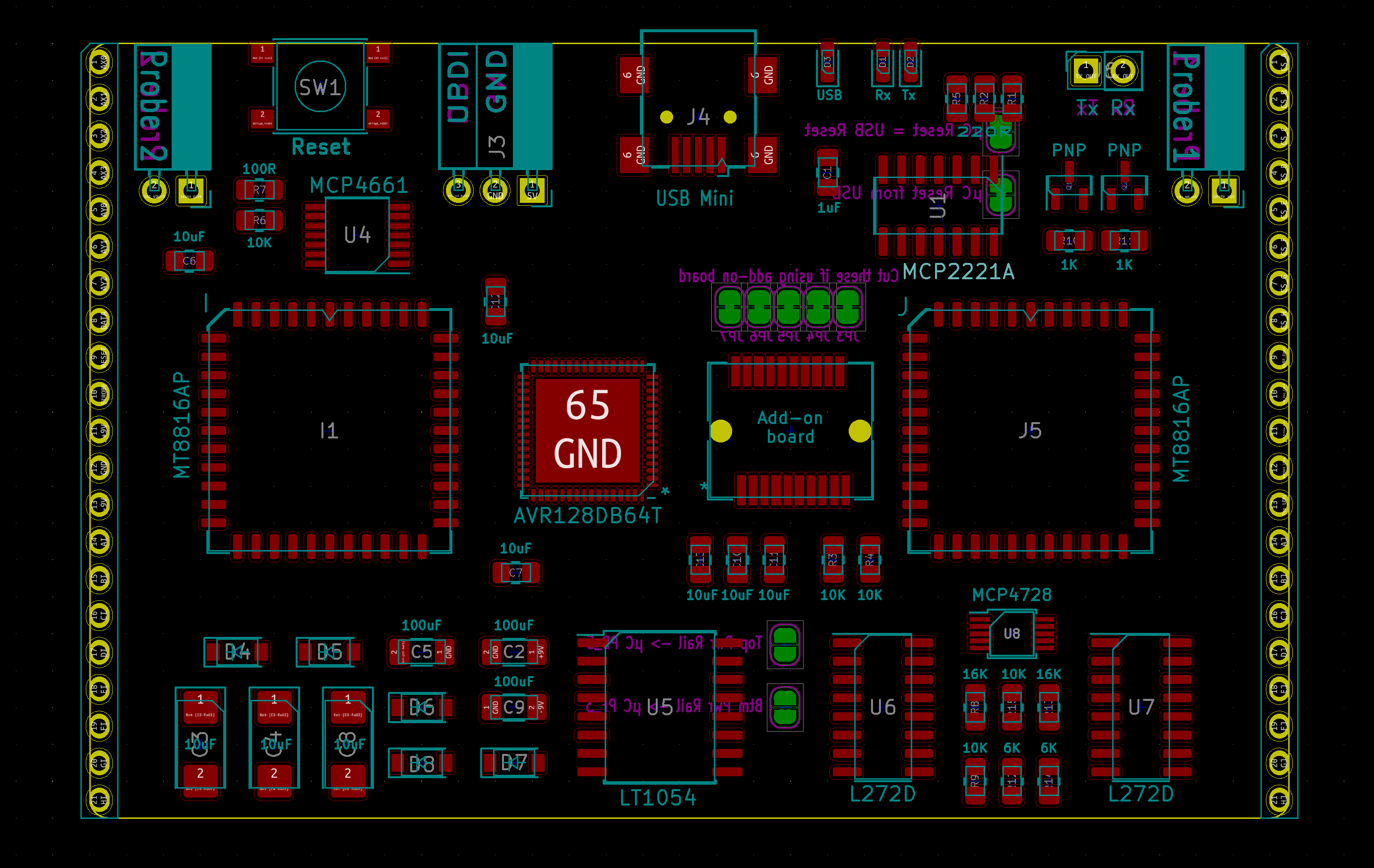
Control Board Changes


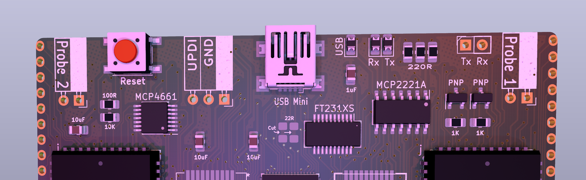
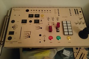
I almost entirely redesigned the controller board so it has a ton of whatever the hardware equivalent of syntactic sugar is. The original was kind of thrown together to make sure the concept of using crosspoint switches like that wasn’t fundamentally stupid (still not entirely ruling that out, but so far it looks promising.) I also just realized I never did a writeup for the first iteration, and I’m not about to go back and do that just to prove that this board is an improvement.
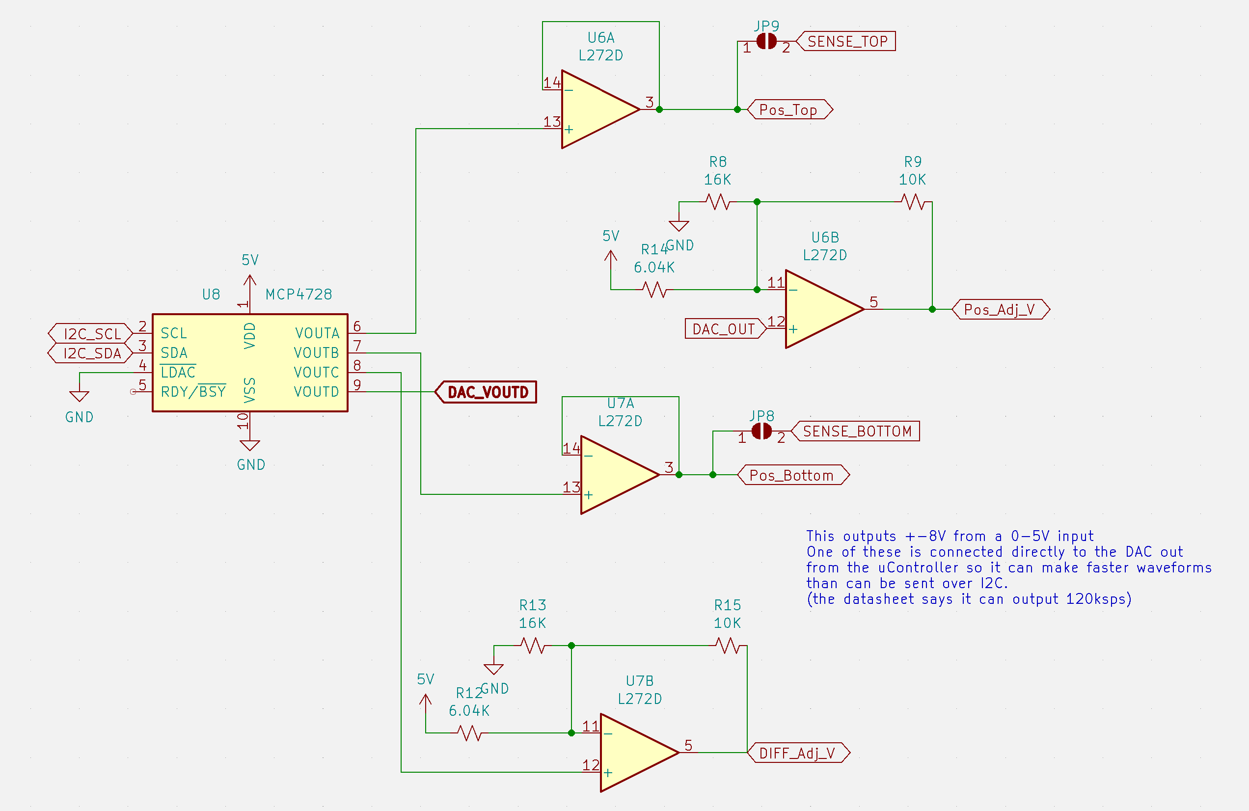
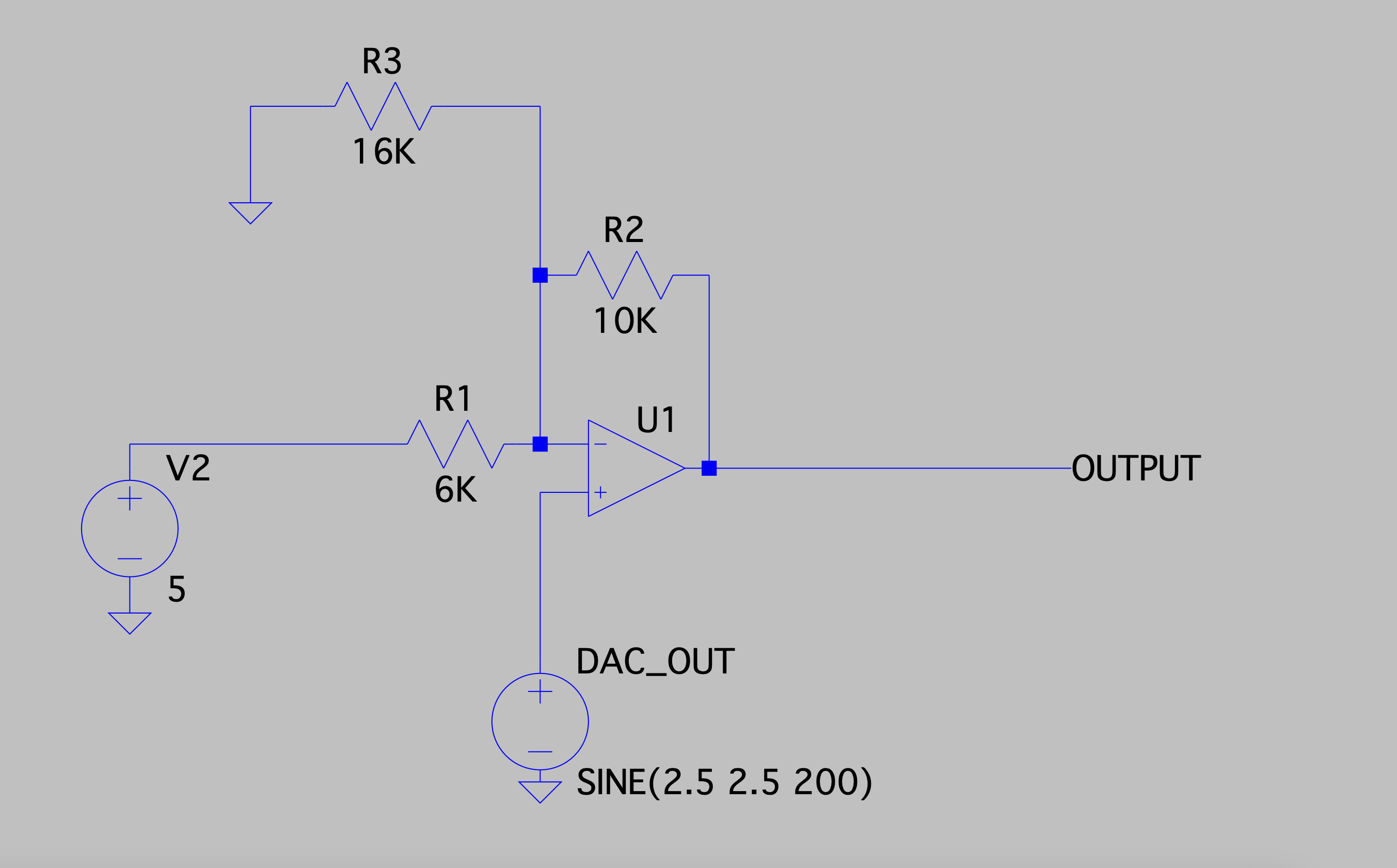
Power Stuff
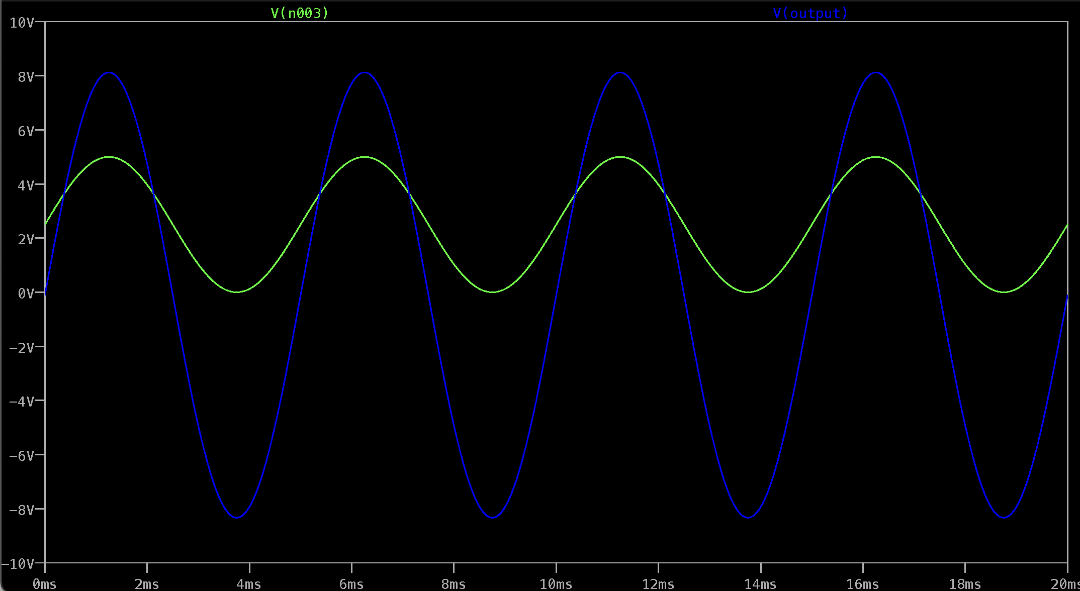
Because I’m going to such great lengths to make everything analog, and I already need a negative supply for the crosspoint switches; I decided to make the adjustable power supply for the rails also be able to do negative voltages. The power stuff still needs some work, right now it gets pretty warm when it’s running and it really doesn’t like it when I remove the matrix board with it on. Presumably because it needs some current draw but I’m not exactly sure why it cares as much as it does (I burned a tantalum cap shaped brand into my finger, you...
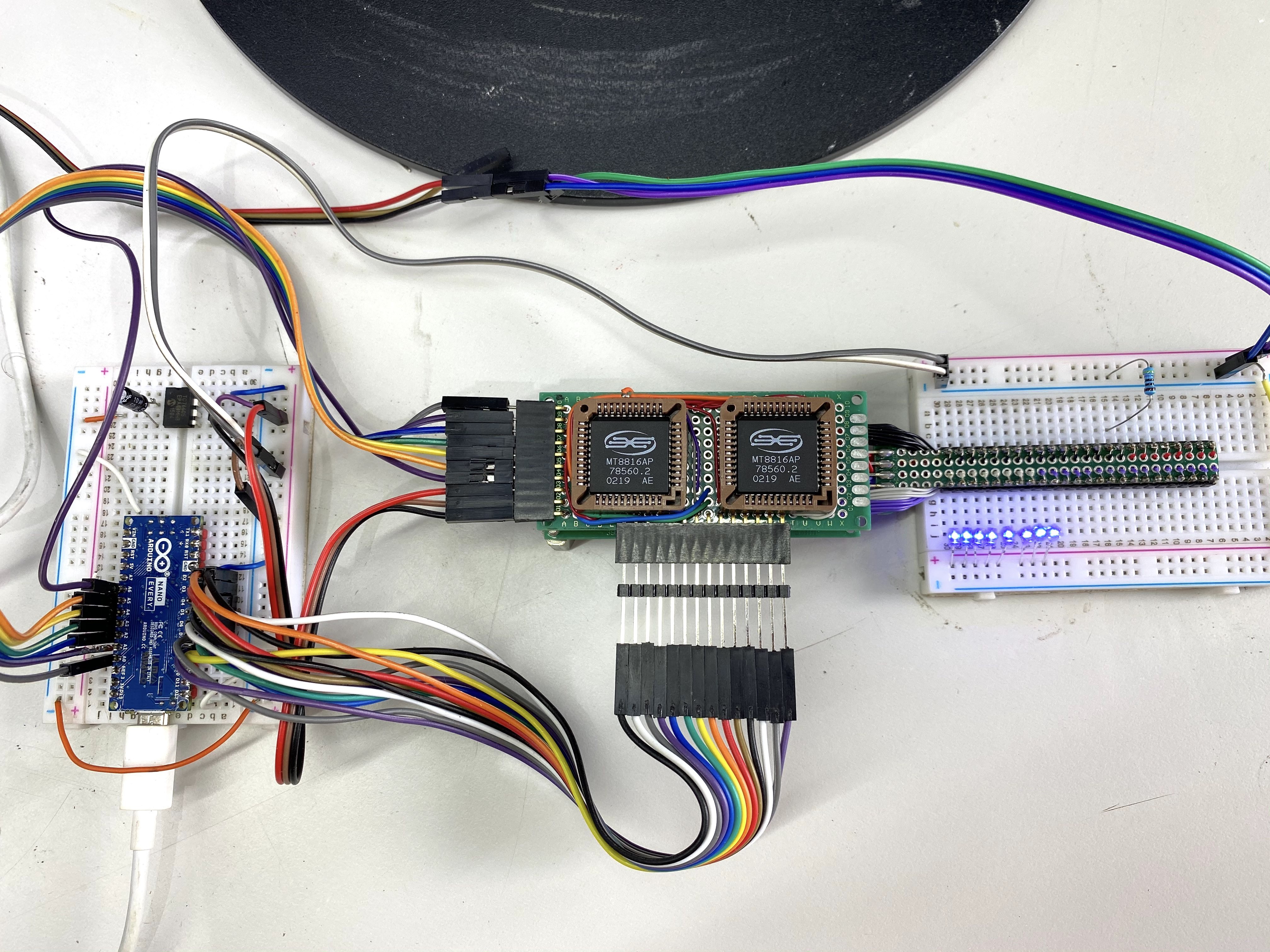
Read more »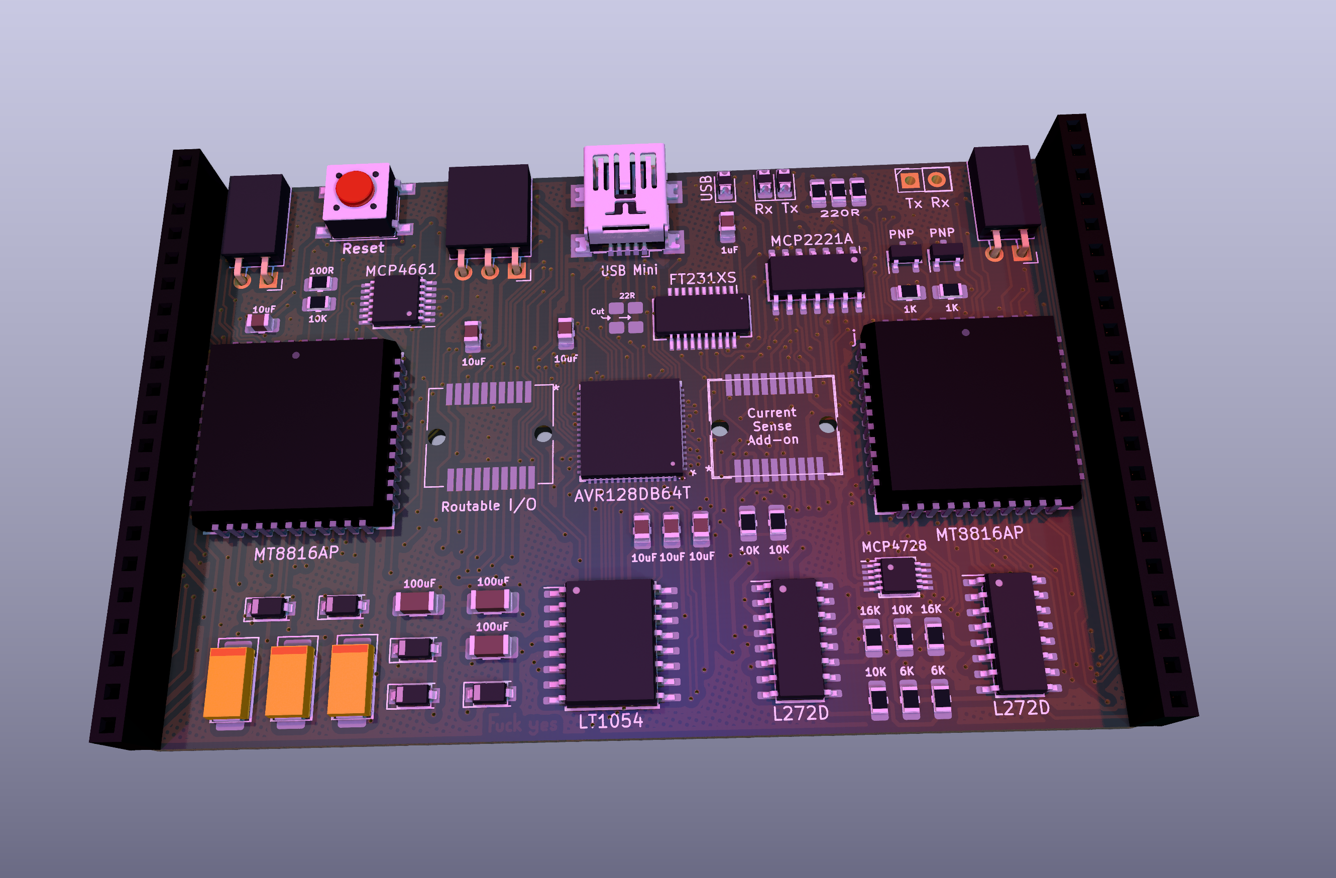 And here it is after removing one of the D's
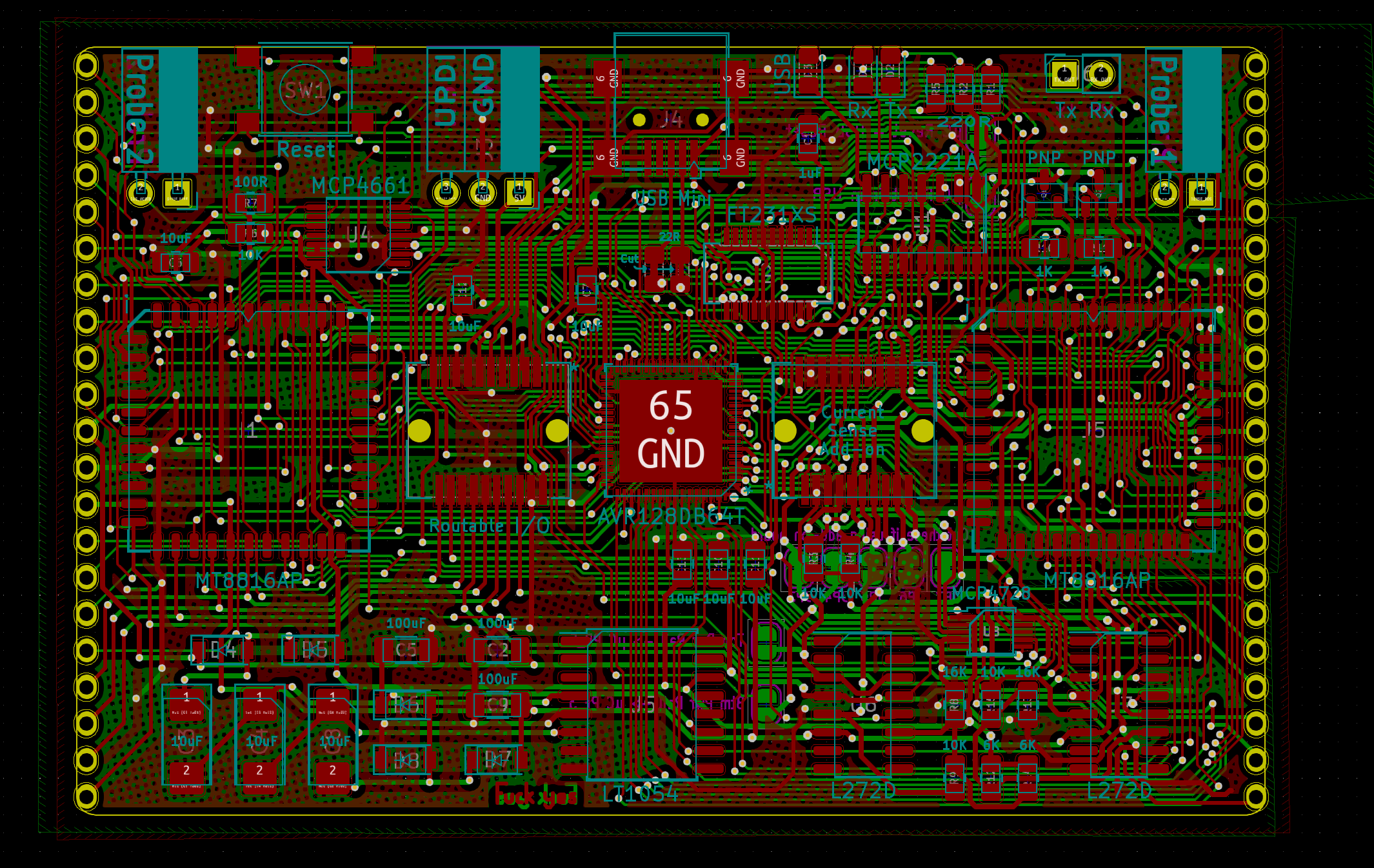


 Matthew Peverill
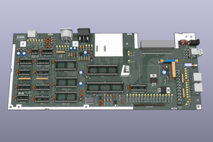
 SukkoPera
 Jared
Jared
 davedarko
I just found out about a program called SerialPlot here on hackaday. It allows you to plot serial data in real time. Its too easy to make BreadWare work with serial plot. I'm gonna make MicroMaster work with serial plot. Its gonna be awesome. So excited.