Close
0%
0%

GPOD

A project to drive NeoPixels (or similar serial RGB LEDs) with an Arduino Nano as a "grow light" for the dark winter months.

Similar projects worth following
Just starting to explore the Tindie/Hackaday ecosystem - my grow light gizmo seemed like a good first project to share. Read on to see how it comes together.

I started by wiring up a proto-board-based grow light driver for Arduino and later converted it into a proper PCB, with an OLED display, a single-button UI and set-it-and-forget-it operation. Added a few features along the way, and I share the various details here for all.

Overview

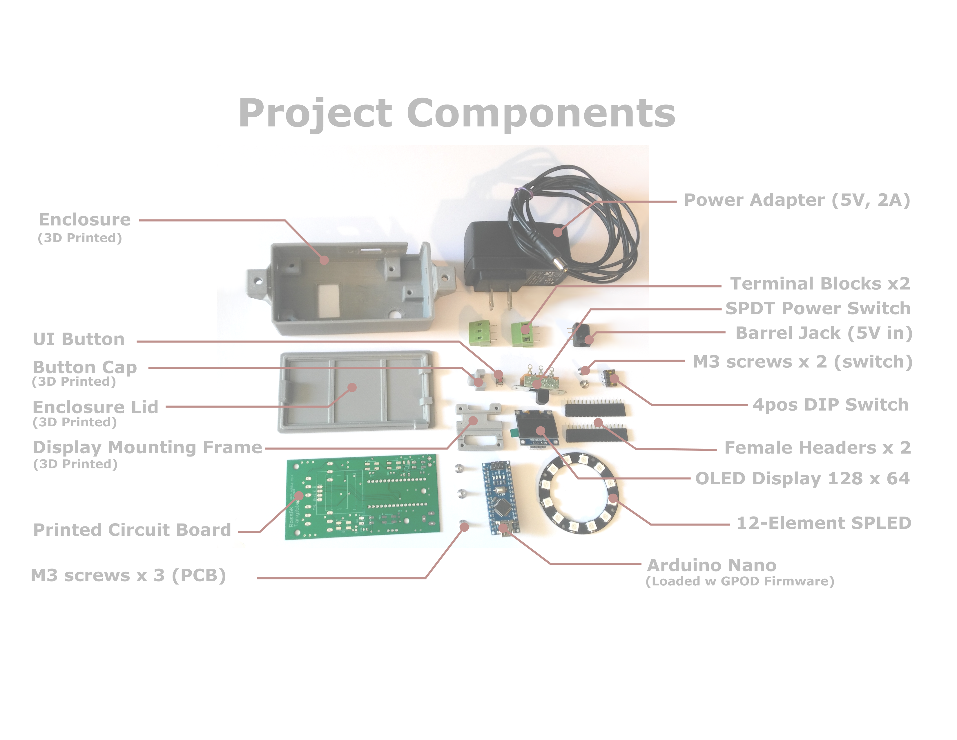
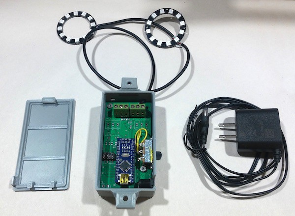
As a second Pandemic spring got underway, and garden plant access was difficult, I decided to grow tomatoes from seed, and a grow light seemed a necessary device. I used an Arduino Nano and a NeoPixel strip I had about which didn't have a useful vocation. Many have these serial addressable RGB / RGBW strips, rings and other shapes laying about.

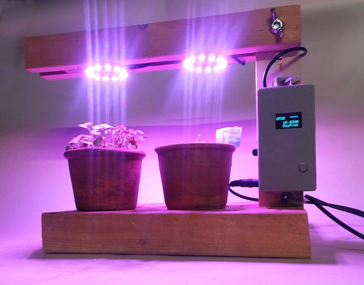
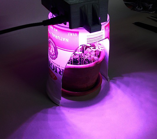
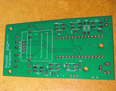
For this project, I turned my February proto-board into a simple PCB. A Tindie-friendly grow-light kit is born. The code presents a basic user interface to set time and then the circuit simply drives day-night cycles to keep plant seedlings happy.  I drive the LEDs into a colour spectrum similar to what one sees with grow lights on the ISS.  If it works in orbit, it should be good for your basement.

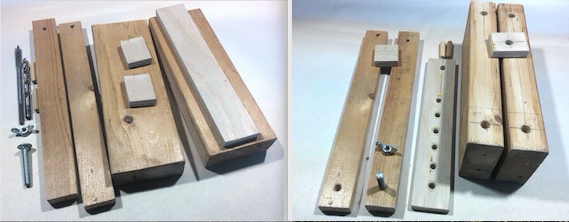
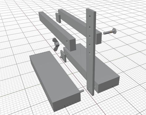
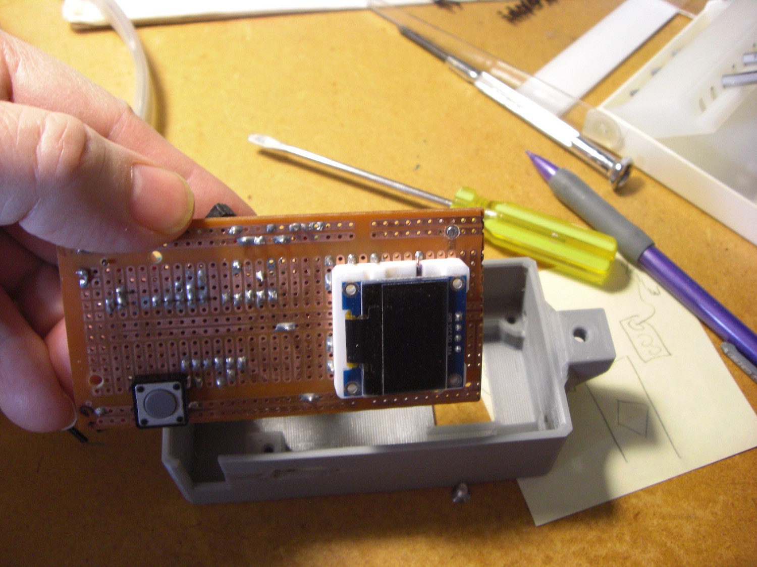
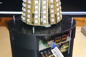
A Simple UI The user interface uses a small 128 x 64 pixel OLED display, and a single button.  A 3D printed case let me bolt the thing to a wooden lighting stand I constructed, and I set it up.

Precise time keeping didn't seem like a necessary features, so I saved the cost of including an RTC.   The clock drifts a bit, but the plants are fine - they just want a day-night cycle, and don't care if it's synchronized to the real sunrise/sunset timing.

The time can be re-adjusted if necessary with a simple button press.  I did this after a couple of weeks to get shift sundown back into something nearer what was going on outside the window.  it only drifts by seconds per day, so no biggy.

The seedlings did well, and I have transplanted them to my garden.  it's the first day of summer as I type this.

A few more pics and details as I get a moment and further explore Hackaday features!

Sharing

The Hackaday photos section seems to limit me to six pics, but I've just discovered the 'Log' feature. So I'll start filling in some log posts (below?) which should be an easy way to share some more pics and words that describe the progress of the project.

PLUS - the system is now available on Tindie, so you can get your own GPOD and play along at home.

  • 1 × Arduino Nano (5V) The older Arduino Nano - compact and inexpensive. Note - 5V version
  • 1 × SP LEDs - in various configurations Serially Programmable RGB LEDs. They'll illuminate when you tell them to, and in any colour
  • 1 × Printed Circuit Board I made a PCB version of an initial protoboard i'd built for a single purpose
  • 4 × Terminal Blocks The screw-clamp version of the handy blocks to attach wires to a PCB
  • 1 × OLED Display A 128 x 64 pixel mini display w/ I2C interface - widely available

View all 9 components

  • Project Parts Documented

    RossGK Tangibles09/10/2021 at 20:03 0 comments

    As the GPOD project is intended to get to know the Tindie and Hackaday ecosystem, I thought I'd take a moment to add additional documentation.  Probably not necessary for most hands-on folks with a bit of experience, but perhaps a good illustration of the overall project for some.

    So I've added an itemized parts view with labels.  Having worked through it, it is a bit tedious, but I think I'd probably do this for future items I put on on Tindie as well.  I think it would give a prospective buyer of the project an good confirmation of what they're getting rather than leaving anything to assumptions. 

    sdf

    Itemized list of GPOD project parts

    For additional clarity for would-be buyers, I created a version with outlines showing what parts are included for each of the three purchase options. 


    I was a bit unsure how to bundle the parts for optimal convenience, but figured there'd mostly be two camps - those with most of the parts laying around already (eg RGB LEDs and a few extra Arduino Nanos) and those with nothing, and wanting just to get the thing and start using it. 


    For the real hard-core makers, I also included the PCB-Only option. Mostly it saves someone the effort of breadboarding up an SPLED driving circuit, and gives them the on/off switch, the power distribution to the four channels, and some SPLED mounting locations on the board for their development process.

    Those who want the PCB-only probably don't want the firmware load and will just be developing their own… but it's there for them on Github anyway if they want a quick way forward.

    Documentation is never fun, but I know I'm always happy to have too much info rather than too little. Especially at the 'should I buy it or make it' phase of a project.

  • Simple Wooden Grow Light Stand

    RossGK Tangibles09/02/2021 at 18:58 0 comments

    A Simple Wooden Stand

    This stand version uses some scrap 1" x 2" and 2" x 4" wood mainly, plus a couple of dowels to assemble the base.   I used a strip of thinner plywood for the vertical mostly because the bolt I had on hand wasn't very long.   What ever thickness of wood you use for the vertical piece, you should also use for the two little spacer pieces. In this case I used half-inch plywood, so some scraps of that worked well for the spacers too.

    Buy a bolt of sufficient length for getting through the top cross piece.


    I did a quick model of the full assembly in Blender as that lets me make an assembly image pretty easily from arbitrary angle.  You can see the spacers between the bottom 2x4" pieces, and the top cross-beam 1x2" pieces. In both cases the spacers are glued in.  The spot where the top cross-beam meets the vertical is held with the single bolt.  With a wing-nut, you can tighten it up plenty tight to stay in place.  The multiple holes allow you to move the vertical cross-beam as your plants or seedlings grow.

    For tools you mostly need a drill and a saw for this design.  A few clamps are helpful to hold things together while glue is drying.  But some masking tape works pretty well for a clamp in a pinch.  Everything here is pretty light, and the end product needs only support the light weight of the SPLEDS (no pun intended, but accepted).

    You can see step-by-step images in the github space. The wdStdMake_xx files show this stand in progress.

    There are many different ways to attach your SPLED arrays or rings or strips to the top cross piece.  I used a couple of staples per ring in my unit shown, but could have just as easily used zip ties, or string, or small screws perhaps.   They are such light weight that some double-sided tape or a dab of silicon glue would work too.  Oh - hot glue is a good choice too probably

    The result is quite functional and I dare say a little bit attractive too. I was happy with the result and expect to put it into service growing some lettuce shortly.

  • Stands for GPODs

    RossGK Tangibles09/02/2021 at 15:22 0 comments

    I hope I'm using this Hackaday Log feature right.  The thing offers 'Add a project log' rather than the more obvious "Add a log entry," so I'm not totally sure if I'm creating many one-entry logs, or multiple log entries in a single log.   Just an illustration of the importance of 'User Experience' (aka UX) people on your development team!

    But I digress, as I try to load a few progress entries here to share what I'm doing on the GPOD project.

    If someone should happen to acquire a GPOD (or build one themselves on their own) they'll probably want a stand for their SPLED  illumination above their plants or seedlings. 

    I built a (probably too complex) wooden one in the depths of winter for my prototype, and got the plants going with that.

    SImplest Possible Option

    I began by trying to think of the simplest structure that someone really new to building things could handle.   As usual, the simplest structure is often no structure at all.

    So what I'd recommend where you can do it, is to just attach your SPLED arrays under a shelf to illuminate plants or seedlings on the shelf below.  An adjustable shelf is optimal, allowing you to move the shelf as they grow. You can probably run the control wire behind the shelf or even just bite the bullet and drill a hole in your shelf if you want to be very neat.

    The SPLED arrays and strings etc are usually very light. I like the n x n arrays, or the rings, and they are only a few grams, so it's easy to attach them with double-sided tape, and not damage your shelf at all.

    A Hack Stand for Hackers
    The next simplest option I came up with is an inverted plastic yoghurt container.  By cutting away a side and punching a few holes, you can put a single ring of SPLEDs into the base and create a cozy little growlight for one pot.  Here's a view of the result with a pot of freshly sprouted arugula.

    Simple Grow Light - A Yoghurt Container

    It was a very simple build and surprisingly satisfying to have a little cocoon of a plant house set up on my bench.

    Next, I thought I'd create something more substantial, yet still simple.  The criteria was that it should require minimal tools, and wooden bits that might be scrap or easily purchased for those with a bit more skill. 

    Just working on capturing the details of that, and will share shortly.

  • Bundled for Tindie

    RossGK Tangibles09/02/2021 at 15:06 0 comments

    The Product Version of the Project

    At its heart, this is still very much a bench-top project, but bundling it together for hobbyists I tried to find a compromise between meeting everyone's interests and just one guy or gal in Wyoming.

    At one end of the spectrum is the board-only approach.  Many of us have the parts laying around to build this, and so getting just the PCB is fine for that situation. Indeed that's how the project came about.  It's nice to just have a clean way to avoid all the flying wires.   So that seemed like the most basic offering.

    My first cut was a spreadsheet of all the parts involved and their costs and I started trying to bundle up a few versions, progressing through subsets of the parts all the way to a fully-built product you could plug-and-play.

    I set up Tindie that way initially, but it was clear that the listing would be too complex and likely lead to someone ordering what they thought they wanted but receiving something else.

    Shipping is Complexsh

    Also, there's the shipping challenge.  With just a PCB, one could put that into a bubble envelope and ship it for a few dollars.  With parts, I need to use a little box, and immediately our (Canada Post) postal service bumps it up into the $15 dollar range.  As well, we are all more happy with a tracking number to reassure us that the package is on the way.  That bumps us into the over-twenty dollar range in Canada. 

    I started again going too complex and offering all those options. On Tindie you create "flavours" of shipping then attach them to your product.  This creates a problem though, as You cannot associate a shipping flavour with a product configuration.  Thus someone could order a bundle of parts, and select the thin, cheap envelope shipping, which wouldn't make sense.

    Simpler is Better

    In the end I stripped all that complexity out and worked the shipping costs into the product cost.   The only selectable shipping options then become tracking or no tracking.  I also wanted to include non-NorthAmerican shoppers, so added something for them (so far tracking isn't an option as the price gets crazy).

    Productized GPOD with two SPLED rings

    Also with the configurations of the product.  I offered both extremes – board only, and fully assembled – then one option in the middle.

    The middle option would solve the tedious bits for an experienced hobbyist.  You get the PCB and the 3D-printed case, and a little 3D-printed frame that centres the OLED display. You supply your own LED strips or arrays, and use your own Nano(5V) and do your own firmware loading, and scrounge up a 5V power supply.

    Because the serially-programmable LED options are plentiful, I initially left those out. However the selection and wiring can be a bit of a challenge, so I later added a few in to the listing, so some can get a few of those if necessary.  Many of us have a few laying around our workshop I suspect.

    Anyway, we'll see if anyone wants a GPOD of their own, and what configuration appeals the most.

  • Build for Sharing

    RossGK Tangibles09/02/2021 at 14:43 0 comments

    A Version for Tindie

    After getting a usable PCB that shouldn't confuse others very much, I thought I was probably ready to share it on Tindie.

    Even though this seemed about as simple an Arduino project as I had around, I realized that throwing it over the wall to someone unfamiliar with it could still have a capacity to confuse.  The solution to that could only be the dreaded D word: Documentation.

    And beyond creating the documentation I would need to share it somehow too.  I was a fan of what Github had been doing, but I was disappointed that it had been acquired by Microsoft, and had removed most of what I had up there, and had been ignoring it for a while.   I didn't know what else I'd use in its place, so figured I'll use it for this project while trying to get opinionated on other repositories.  I'm still a big fan of the GIT tool itself.


    Documentation

    I set about writing a simple PDF file, and a text-only version as well. 

    For the text-only version I put together something in MarkDown which is nicely compatible with Github.  I think the docs (which few will probably ever read) should give all a good idea of how to make the most of the little project, if they wish to know more.

    I also put the schematic and code up there of course.

    You can find the github site here, and just put together the project yourself if you wish.

    Listed on Tindie

    With documentation and a usable circuit board in hand, I did a quick inventory of the parts I have around and offered the GPOD for sale on Tindie.  

    I figured I'd just get it out there now, and add some additional information and features to my listing afterwards, as it will probably take a long while before anyone interested finds it. In case you're one of those intrepid folks, you can find the Tindie listing here.

    Next, I am working on some additional info to help users who want to set up their own grow light figure out how to build one.

  • GPOD - From Proto to Product

    RossGK Tangibles09/02/2021 at 14:07 0 comments

    GPOD Log Begins

    My GPOD project is a vehicle to explore the Hackaday and Tindie ecosystems. I picked this little prototype project to convert to a sellable item, and share the broad elements of the progress.

    Only just noticed the existence of the "LOG" feature here, so I'll add a bit of info as I go along. This looks dangerously like a blog, and if the early 2000s showed us anything there are only two types of blogs - those that have been abandoned and those that are soon to be abandoned.   I'll try to at least bring this to a conclusion with a finished device on Tindie.

    The Story So Far
    So far I've taken a circuit made on veroboard (prototyping circuit strip board) and turned it into a PCB.  The circuit is essentially of the 'hat' variety, a board that connects to an Arduino board and provides interconnectivity.  However, maybe in this case it's more of a 'shoe' as you don't plug this into the Arduino, the little Arduino Nano plugs into it.


    My prototype was a simple grow light to get some plant seedlings growing during the dark months of the winter.  It was quite successful, and I've been enjoying the literal fruits of the labour all summer, eating lots of tomatoes, cucumbers and kale.

    Perf Board prototype going into a first cut 3D printed box


    The circuit simply provides power routing and connectivity for connecting the common serially programmable RGB LEDs to the Arduino.  And I used the older 5V Nano Arduino because a) I had a few around not being used, and b) those SPLEDs tend to use 5V as well and I could keep the power distribution more simple.

    I also have an OLED display screen to present a simple user interface, and a single button to control the UI.


    PCB Evolution

    After the first PCB I decided to make another version because there are always a few things you realize you could've done better after you have it in your hands. I also decided to add a few spots to put SPLEDs directly on the board for development purposes. Sometimes you want to write some code to control them, do various colours or patterns etc. 

    Circuit Version 3 circuit board

    The board has four 'channels' and this allows mixing of different types of SPLEDs. Some are RGB, some are RGBW, and ther are a variety of different signalling methods.   The code library I used to talk to them (Adafruit's) allows for all those conditions, so I also added a switch to the board to select between two of the most common approaches.

View all 6 project logs

Enjoy this project?

Share

Discussions

RossGK Tangibles wrote 09/03/2021 at 14:27 point

Half right - plants prefer a wavelength that extends into the UV where the RGBs can't go, but it's not a narrow band - it's rather broad.

For photosynthesis plants want wavelengths that the chlorophyll molecules can absorb. These are in the blue (410-460 nm) and red (630-670 nm) light range. There are 2 types of chlorophyll: 'a' (max absorption at 430 and 662 nm) and 'b' (max absorption at 453 and 642 nm).  

Chlorophyll a & b activity centres around 390 to 480nm;  Another key light-activated component - carotenoids - like it from 400 to 500nm, with a bit of additional activity in the 625 to 680nm.

Typical RGBs have a blue component at 465 - 475 nm, and a red at 620 to 630nm.  So some good overlap there.

Bottom line is that they're pretty happy with the wavelengths produced by the RGBs.  I have three rows of vegetables I've been eating all summer that spent their first two months under the RGB grow lights.  The results are clear.

Absolutely they'd be even happier with some 410 - 465nm action, sure, but they do well even without it.

I was avoiding the biology details in this forum, but thanks for the opportunity to share it. 

And regarding cheaper, this is mostly about finding another use for SPLEDs that one might have laying around.  Plus the pre-made arrays are very cheap, so it's nice and convenient to pick up a ring of six or twelve for a few bucks. 

Have fun  with your projects.

  Are you sure? yes | no

unl34shed wrote 09/03/2021 at 08:38 point

Basically not a bad idea, but using regular RGB LEDs won't really work as grow lights. Plants need specific wavelength, that typical LEDs can't provide. There is none to very little response to green light, and more in the red and far-red as well as blue and if I remember correctly even some uv spectrum.

Also you might not need all LEDs controlled individually and it might be cheaper to just have several PWM channels for the individual colors.

  Are you sure? yes | no

Does this project spark your interest?

Become a member to follow this project and never miss any updates