 Christian
Achitekture
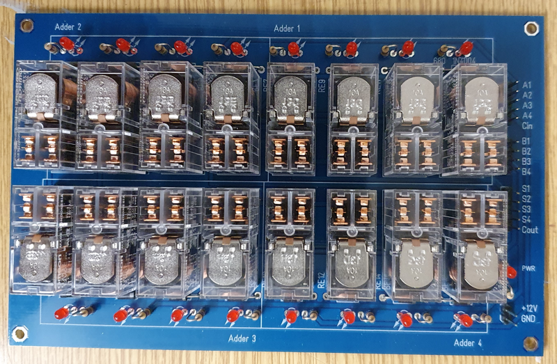
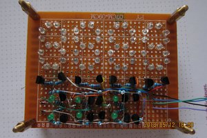
And in real life:
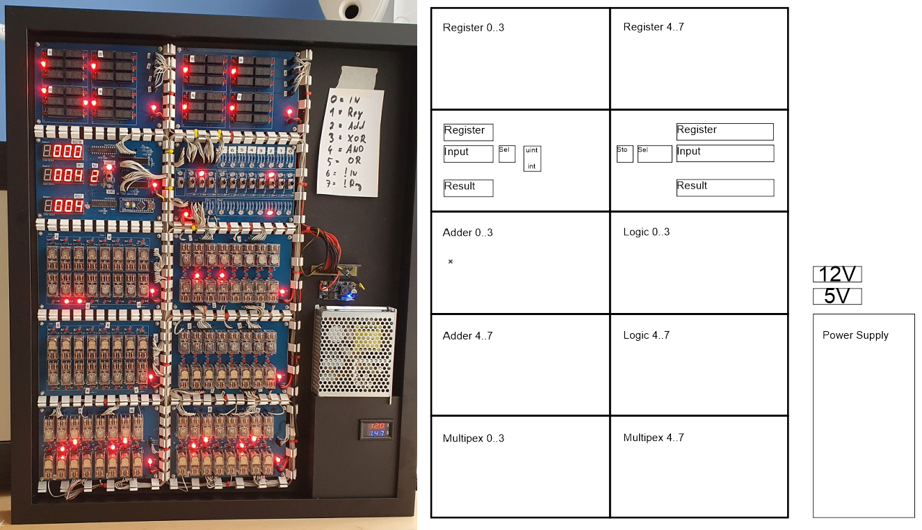
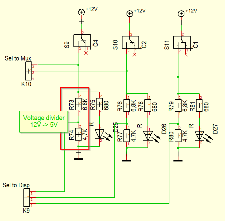
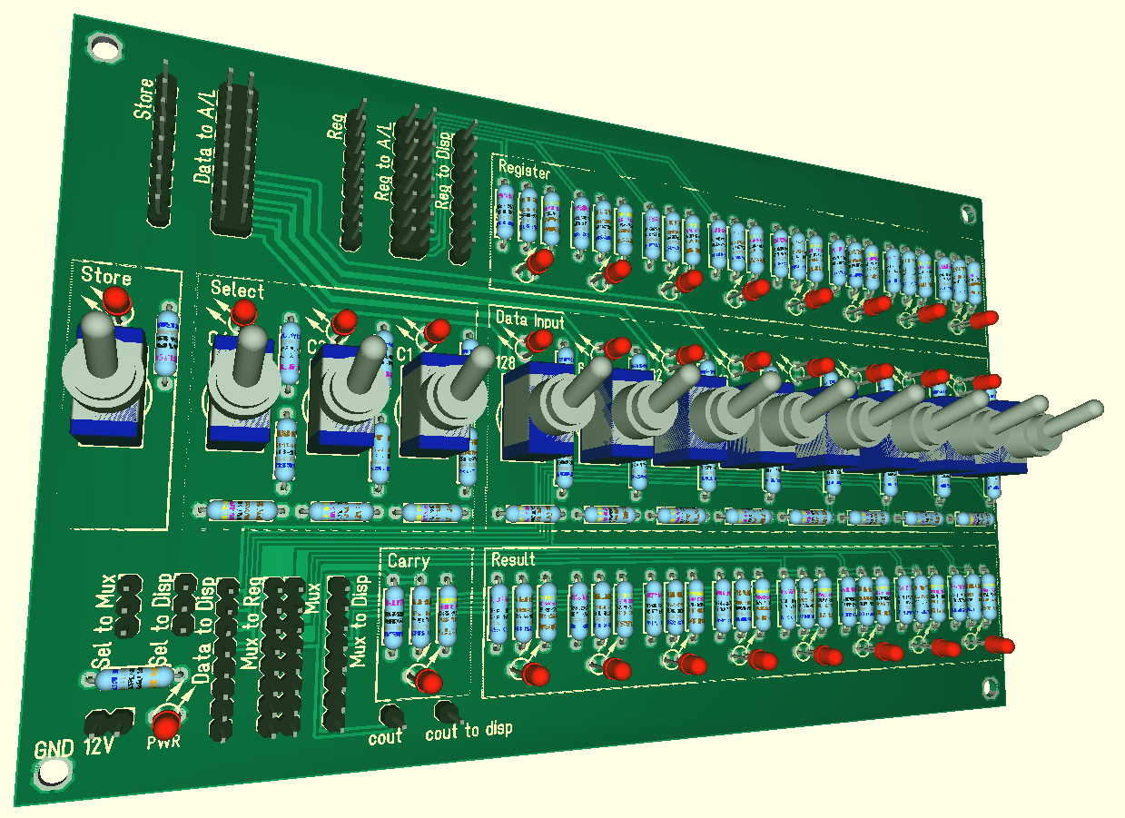
The data input, select and store switches are mounted on the I/O board. For every data line (input, register, result and select) a LED displaying the status of this line is mounted and a voltage divider (12V to 5V) to feed the states to the display board.
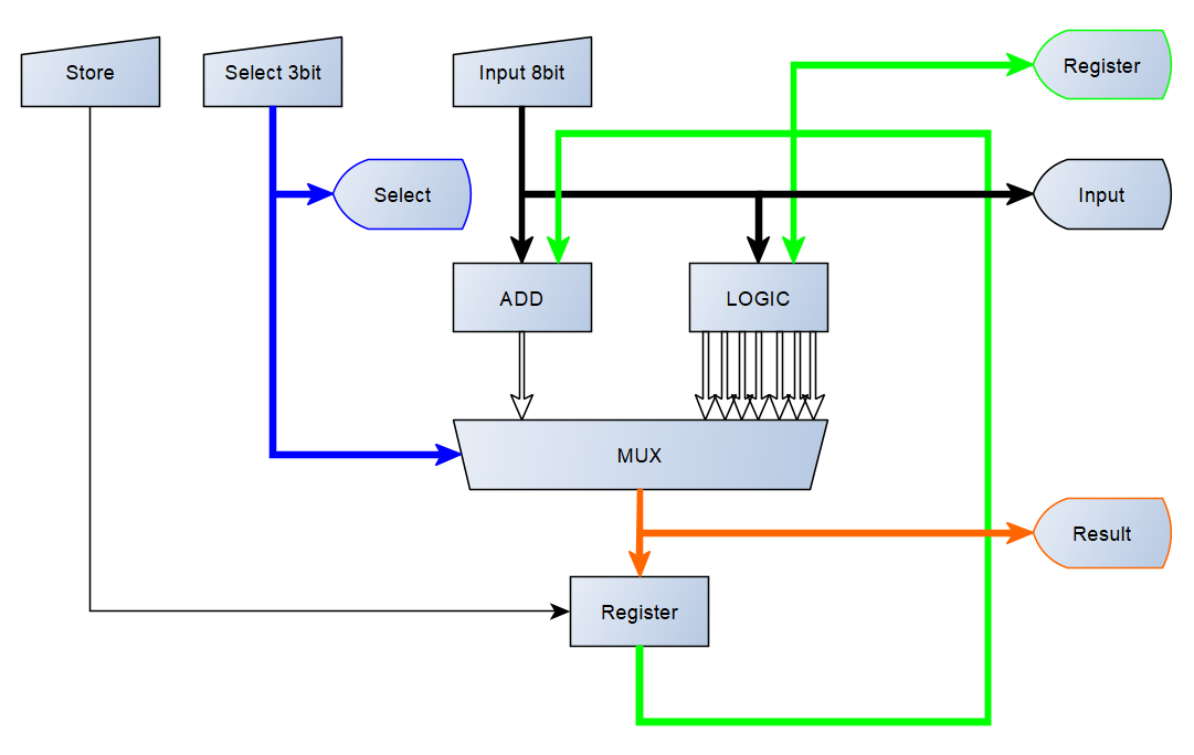
All data lines of the I/O board and the register are always connected to the inputs of the adder and the logic circuit (no input multiplexer). The (output) multiplexer then selects the operation that is forwarded to the result lines.
The multiplexer is wired as follows:
| Select | Result | |
| 000 | 0 | = Input (LD) |
| 001 | 1 | = Register (NOP) |
| 010 | 2 | = Add(Register, Input) |
| 011 | 3 | = XOR(Register, Input) |
| 100 | 4 | = AND(Register, Input) |
| 101 | 5 | = OR(Register, Input) |
| 110 | 6 | = NOT(Input) |
| 111 | 7 | = NOT(Register) |
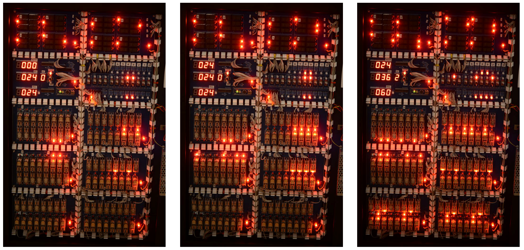
Example: 24+36=60
- Enter the first number at the I/O board (24 in the example below)
- Select 000 [0] at the multiplexer: result = input
- Press ‘store’ à the first number is stored in the register (24 is displayed in the register)
- Enter the second number at the I/O board (36)
- Select 010 [2] at the multiplexer: result = register + input (result = 60)
For easy reading, all numbers are also displayed on a separate board on 7-segment displays. This cheating board aka “easy-to-read-display” allows to select between displaying signed or unsigned 8bit numbers. This way it is also possible to subtract.
Some Notes:
- If you want to know more about CPUs, read "Code: The Hidden Language of Computer Hardware and Software" by Charles Petzold
- For the documentation I created parts of the circuits with the Circuit Simulator version 2.5.7js http://www.falstad.com/ (see files: *.circuit)
- If someone is interested:
- Circuit, PCB development and rendering of PCB images was done using Target 3001!
- 3D printed parts were created using Solid Edge
Parts summary:
- PCBs
- 72 1N4001
- 3 220R
- 106 680R
- 2 10k
- 37 4k7
- 28 6k8
- 48 Relay G2RL-2 12V
- 24 Relay M412H
- 13 Switches
- 110 LED
- 1 Arduino nano
- 3 Display CX56-12
- 2 MAX7219CNG
- 2 MCP 23017
- 192 cables (dupont connectors)
- picture frame
- power supply (Meanwell 12V, 6A)
- buck converter
- Volt and Ampere Meter
- Mains connector
- Power switch
- Screws, nuts
- Plenty of time

 With DTDP relay this can be built as follows:
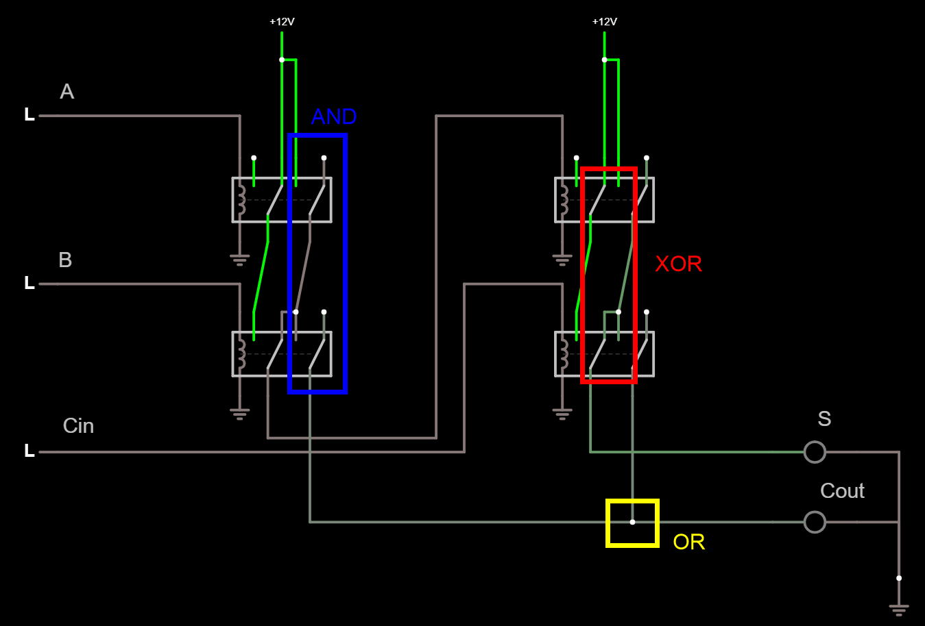


 Pavel
Pavel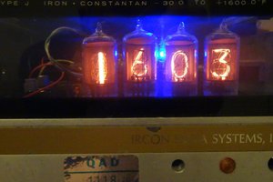
 Ken Yap
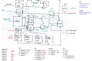
 Phil Wright
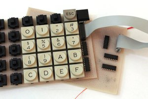
 Yann Guidon / YGDES
Nice job, looks very similar to the work here: http://www.electronixandmore.com/projects/relaylogic/index.html