-
Practicality
11/15/2021 at 18:33 • 0 commentsFinally!
Tap has gained a practical use case!https://twitter.com/XasinTheSystem/status/1460379972506423305
One of the things this project has been lacking for a while now is something to show that it can actually do something. Not just a little flashy demo, but, at the very least, some action that can help in the real world.
And it now has this!
The video above has a little demonstration of a basic but effective "Debate Club Timer".
In essence, it turns Tap into a little clock that counts down the time you have remaining for your talk, but it does so utilizing most of its outputs.The OLED screen gives the exact time remaining, while the ring of LEDs gives a quick glance at how long is left. The ring's colour also signals the first and last minute of the debate, which gives a bit more warning when approaching the very end, and the speaker accompanies these changes using warning beeps that signal the last 30 seconds.
And if you go over the time?
It flashes a bright red to show that you probably, maybe, should stop talking now.Expect more little demonstrations in the future. Tap is finally ready to step out of the "probably" and into "Yesss, it finally works!"
-
Putting the Tap in "Tap"
11/02/2021 at 22:35 • 0 commentsTap is a tiny device with limited capabilities to receive inputs from users.
Still, being able to somewhat fluently navigate simple (or more complex) menus and input forms to activate programs and interact with connected devices is quite important!The video here shows neatly how I managed to still get such input methods to work on Tap, despite the absence of the main sensor:
https://twitter.com/XasinTheSystem/status/1455661802298150916
Initially, Tap was designed to use a gesture sensor with a 32x32 pixel grid of IR sensors, that could detect a hand waving in front of it to extract gestures. It can even provide a cursor position based on hand or finger position!
Alas, it was out of stock at the time of ordering the board, and is only sparsely available on DigiKey at the moment.
As such, an alternative was used - the built-in LSM6DS3 gyro and accellerometer. This device features built-in detection of hard taps, and has surprisingly precise acelleration and rotation-speed outputs.
It, quite literally, allowed me to add tapping to "Tap"!
In this update of the software, I used the various inputs from the LSM6DS3 to provide simple but varied enough input methods to navigate folder structures through the device, such as menus!
It's not exactly what I was hoping for, but the component shortage is still about, and I can make do.Once the main gesture sensor becomes available again, it will be a simple matter of tweaking the code to trigger forward/back/left/right gestures based on perhaps a combination of both sensors - who knows!
-
Screening for bugs
11/01/2021 at 22:29 • 0 commentsWell, arguably one of the most important features of the Badge is finally operational, as you can see in the demonstration video in the Project Details!
However, getting to that point was a little tricky - and had a little surprise in store for me to debug!
An almost recognizable Hello World!! Read on below to see how this slightly oddly wired OLED panel confused us for a while, and how eventually it too was brought under control~
---------- more ----------OLED screens such as the module for Tap are, all in all, very easy to control.
The display here is a little 64x32 screen based on the popular SSD1306 IC, which has many libraries and fairly good documentation.We even had a library written ourselves, which, without modifications, gave the result above - a somewhat readable "world", though the lines weren't drawn properly, and things seemed quite misshaped, all in all.
No bother, all OLED screens need a bit of tweaking in terms of the output muxing and interleaving of columns - but even after correctly setting these options according to the manufacturer's datasheet, the display still didn't behave quite right.
For one, the column/page wrapping options seemed to be ignored despite trying different ways of setting them up. This meant that instead of properly writing one page of data (which means eight rows, or one byte per column), and then wrapping on to the next, it would keep overwriting the same page, over and over.
This was the easy part to fix, by simply switching to a page addressing mode and manually wrapping to the next page. This means a little more I2C overhead by having to re-set the writing position, but it's minimal.
The second problem, however, was far more interesting.
See, the SSD1306 is actually meant for 128x32 pixel displays. It has a very strict mapping that essentially forces certain RAM addresses to physical pins, which can not be changed. Unneeded rows can be disabled, but unneeded columns can not.When it comes to mapping a 64-pixel wide display onto these 128 pixels, one would assume that some sane parameters would be chosen, such as centering or aligning it to one of the edges.
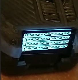
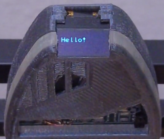
The manufacturer of this screen, however, chose the very peculiar value of... 36 pixels of shift. Presumably, this simplified the hardware layout, but since this value wasn't documented, it made for a weird last hurdle to figure out.Using a binary pattern to identify how the columns were mapped from RAM to physical layout made it easy and quick to determine the correct offsets needed! Once all was said and done though, finally nothing stood in the way of making an old-time classic happen - the good old "Hello World"
It certainly is a rite of passage when getting a new program or hardware running, and Tap has officially passed this moment.
Next up will be making actual, practical use of Tap.
This includes cleaning up the software to provide cleaner interfaces, making the ring of LEDs work better, and perhaps adding a basic UI experience.I am especially looking forward to getting the actual "Tap" in Tap to work - it's not just a funky name, you know?
-
One step forward, two ICs back
10/14/2021 at 11:54 • 0 commentsLet's cut right to the chase - the item that most of you will most likely want to see:
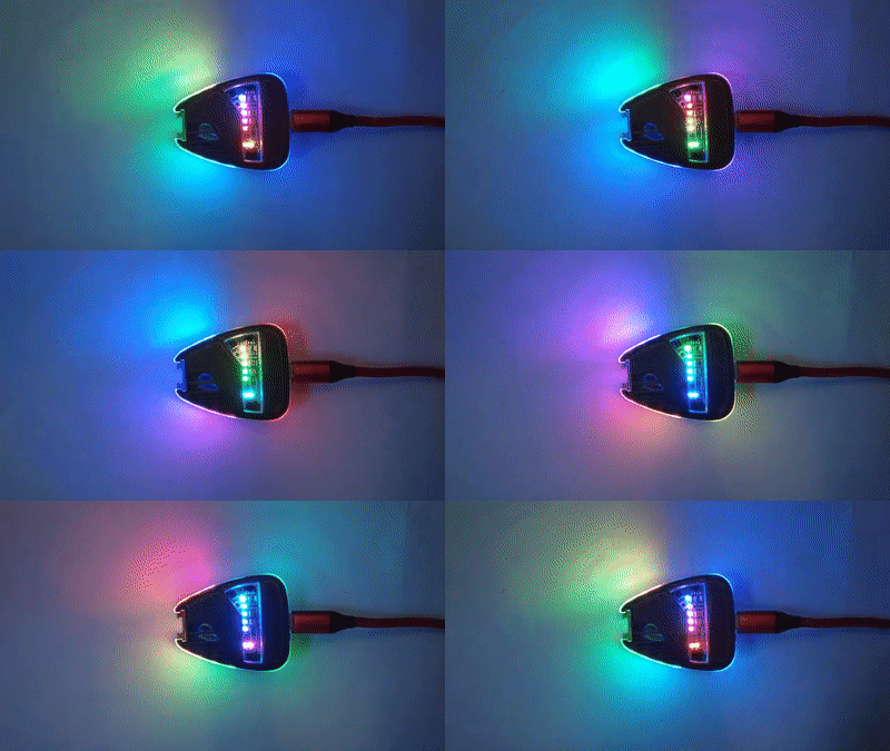
![TapV2's LEDs in action TapV2's LEDs in action]()
After fixing a bit of rogue code, the LEDs now work perfectly, and give the badge a stunning aura TapV2 has been soldered and has booted right up!
It was not, sadly, quite as first-try as we had been hoping, and a bunch of issues came up that will need to be fixed, but it's nothing major.
Look below the break to read up on how things went, what went wrong, how it almost blew up on us(!), and how we'll deal with that in the future!
---------- more ----------Soldering
Soldering took place across a few hours, and went rather smoothly, all things considered!
Pre hot-air, in the middle of placing all the little caps. 0402 was a bit more challenging than usual, but by far the toughest little bean were the ridiculously small XQFN LDOs, five pads but only 0.5x0.5mm! After some hot air and hand-soldering on more sensitive components such as the LEDs, whose plastic casing would've melted, the badge was now ready for testing! Mostly. All the soldering was completely on a single day, and actually went fairly smoothly!
Despite the fiducials, no automated P&P was used - all the components were laid down by hand, which made for a slightly stressful, mostly soothing day of carefully laying things down.Sadly, a few parts either weren't there to begin with due to supply shortage, melted during the soldering, or had to be removed again.
These are:- The STM32 and APDS-9500 are both missing due to component shortage, and there's no good way to ever really reach them, so for now they will remain out of reach.
- An old project was cut open to extract a MAX audio amplifier and LSM6DS3 MEMS IMU. Sadly, the IMU didn't make the transfer and had ended up shorting the power line, heating up in the process - it was desoldered again after testing, and a replacement sacrificial breakout board is on its way.
- The STM ToF sensor just... Melted. Not really sure who thought that regular plastic was a good choice for it, but it didn't withstand the hot air gun for long enough and was unusable, so it was removed before it was even fully soldered.
After soldering things up, a first test was performed, and... It was successful!
Most voltage lines were at the correct level, and the board drew only 20mA, which is what the ESP32's core would soak up without light sleep, so all seemed well!The board right after loading a test program. Odd, all LEDs should have had the same colour here, but were flickering eratically - a bug-chase ensued and soon found the issue!
The LEDs at first refused to work, as usual, but it turns out we had a bug in our NeoPixel code that... Somehow hadn't caused enough troubles for the past three years to be noticable? But it was quite easy to fix, and after adding a pragma pack(1) statement where it belonged, all seemed well enough.The aftermath
Sadly, even though the LEDs were fixed easily, more problems were on the rise.
As we went to try and fit the PCB into the casing, it snagged and didn't want to close. It turns out the side-mount LEDs were a little too wide, and the clearance of the top half of the casing rubbed against them.
The bottom half also didn't leave enough clearance for the JST PH connector to wire up the battery, so both halves of the casings need to be reprinted. However, the way the diffusor looks is... Stunning to say the least, and breathtaking, to be honest. It looks better than I could have hoped for :)There was one last, big issue that we still had to tackle:
While re-reading up on the battery charger IC's datasheet, which we mainly did just to be sure, we discovered, to our horror, that we had ordered a 4.35V battery charger by accident!!The BQ24232 was the one we had wanted, but was out of stock. DigiKey had listed an alternative, the BQ24232H, which was also described as 4.2V Li-Ion charger...
That, however, was false. The H stands for high-voltage, and it very distinctly will overcharge the LiPo ever so slightly.If we had not looked at the datasheet beforehand, this would have lead to a very unpleasant surprise after charging the battery for the first time!!
This, however, is not something we can easily deal with. The regular 4.2V charger is far from easily available, and will only be in stock by the end of 2022 - almost 2023!
For now we can still discharge the battery using it or power the system from USB only, but can only cautiously charge it up, leaving Tap without a safe battery system.What's next?
So, what to do about all of this?
Well, luckily we can still start work on the most important items of the badge. The ESP32 works, the board can be powered without a battery, and once the replacement gyro and OLED screen are soldered in we can start working on the UI and a few first features.However, with the star of the show, the Gesture Sensor, completely missing, and the battery system crippled due to the missing STM (which would have handled power-sequencing to reduce idle current) and wrongly numbered charge IC, it will take a while for the badge to show its full potential.
That certainly won't stop us though, and between the speaker, mic, LEDs, screen, BLE connection, BME680 and so on, there is enough to keep us busy for the next few weeks!
-
Case closed!
10/01/2021 at 22:41 • 0 commentsIt's been a little while since the last project log, but don't worry, things have been moving forward quite well. The most impressive sight of this is, of course, the completed casing, so I shall let you wait no more:
Read up below the break to hear about adorable tiny components, the PCB, and designing and printing the case!
---------- more ----------State of the casing:
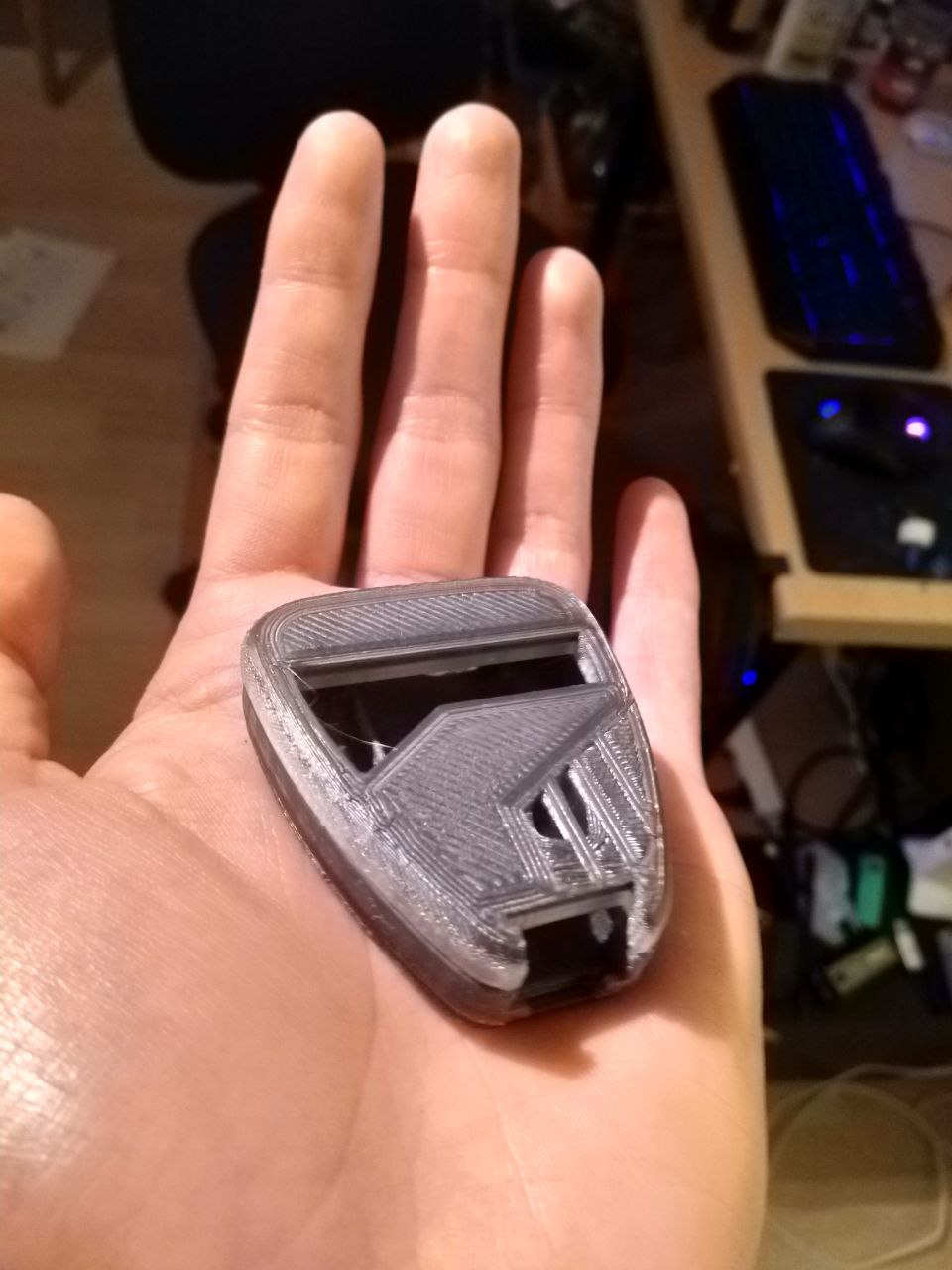
Over the last... Three days, actually? The casing has come a LONG way.
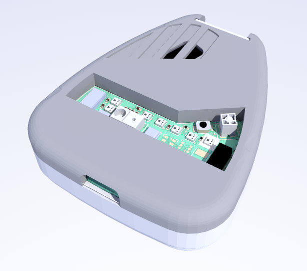
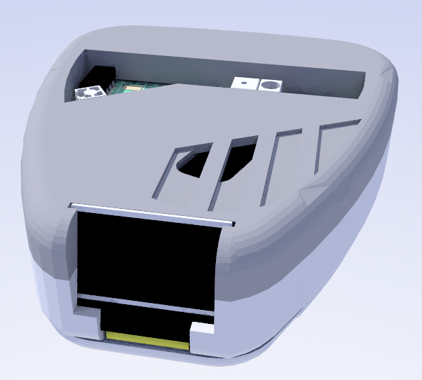
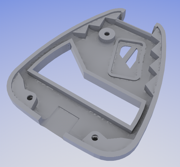
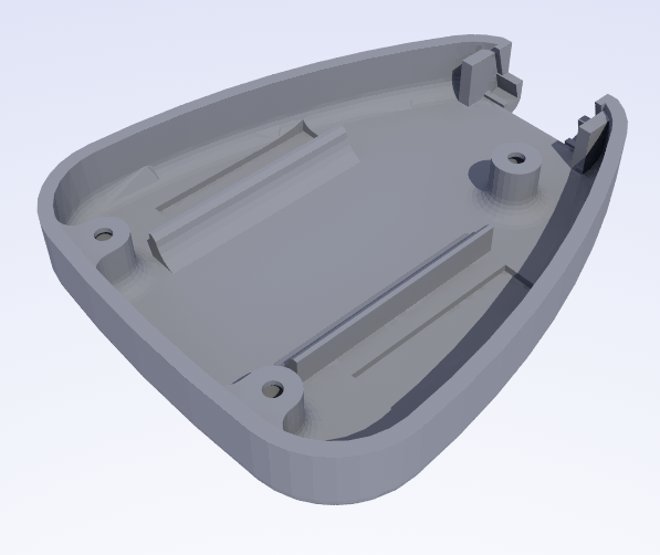
Believe it or not, but aside from a few glitches that FreeCAD threw in, nothing that was not fixed by a restart or refresh, it held up incredibly well. It certainly is a tribute to people like Realthunder that we have such a capable FLOSS CAD available.Words always fail to describe the design well, so here are a few images of the casing as modelled:
No screws are visible on the front - nuts are embedded during the print to conceal any meddling! It's carefully held by the two halves and will face the wearer at a comfortable angle. Its 32x62 pixels will give great readouts! The assembly of the casing has been a little tricky, and despite being less than a day old it already has a second revision.
The first model had too small of a pin on the bottom that held the screw nuts, which led to a weak point that failed rather quickly.
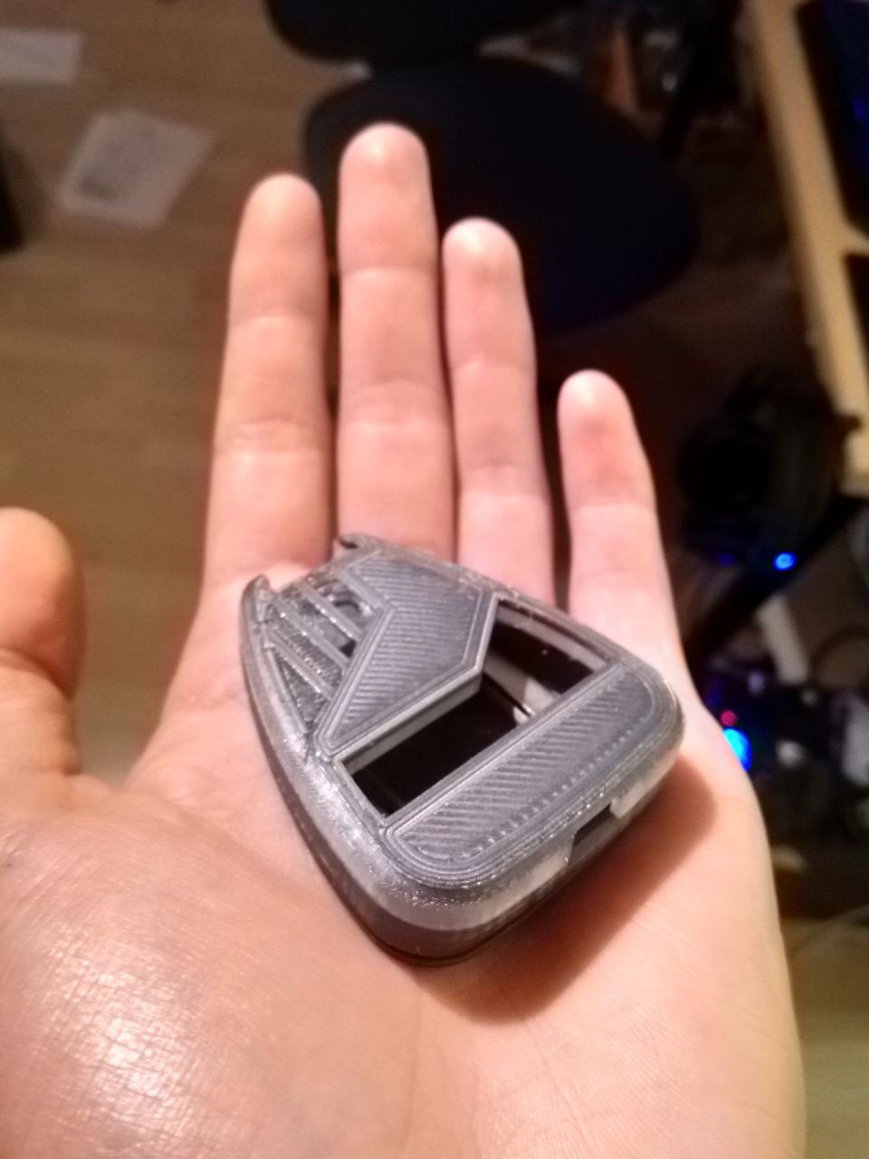
This was already mitigated by using larger diameters and a bit of extra spacing, just to be sure.The print itself is also a little more adventurous. It must be paused twice, once to swap the filament for the top half to a translucent material, providing a see-through "halo" that is later illuminated by the outwards-facing LEDs, and a second time to insert the nuts, which will be printed over to provide embedded threads. As they are tiny M1.5 screw nuts, actually getting them in there is finicky, but works well enough!
All in all, the casing looks great, and once the PCB is inserted to keep the halves aligned (as the PCB itself serves as a middle piece between the two halves), the casing will be sanded down to fit.
Have a look:
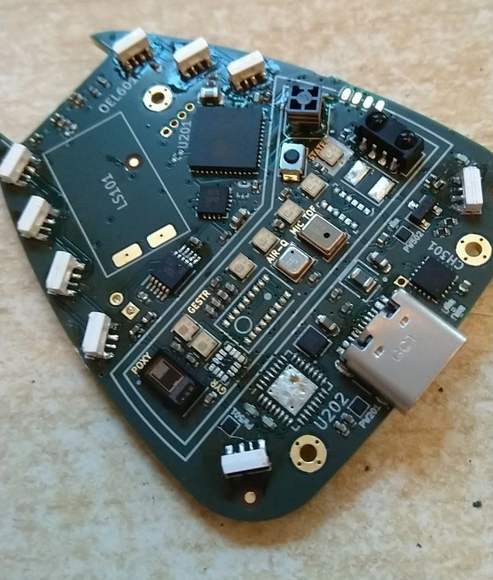
State of the PCB
The PCB has also been ordered not too long ago!
Aisler will still need a few days to manufacture it, and with how the design ended up, we will need to hope that they don't run into issues.In fact, their Gerber post-processing almost deleted a few traces without any warnings on my end, and also forgot to actually drill the screw mounting holes.
Someone really needs to change that... But I digress.The components, however, have arrived after just barely more than two days, which is a record even for DigiKey. It was like a surprise tiny Christmas - and truly tiny at that. Just take a look at some of our favourites!
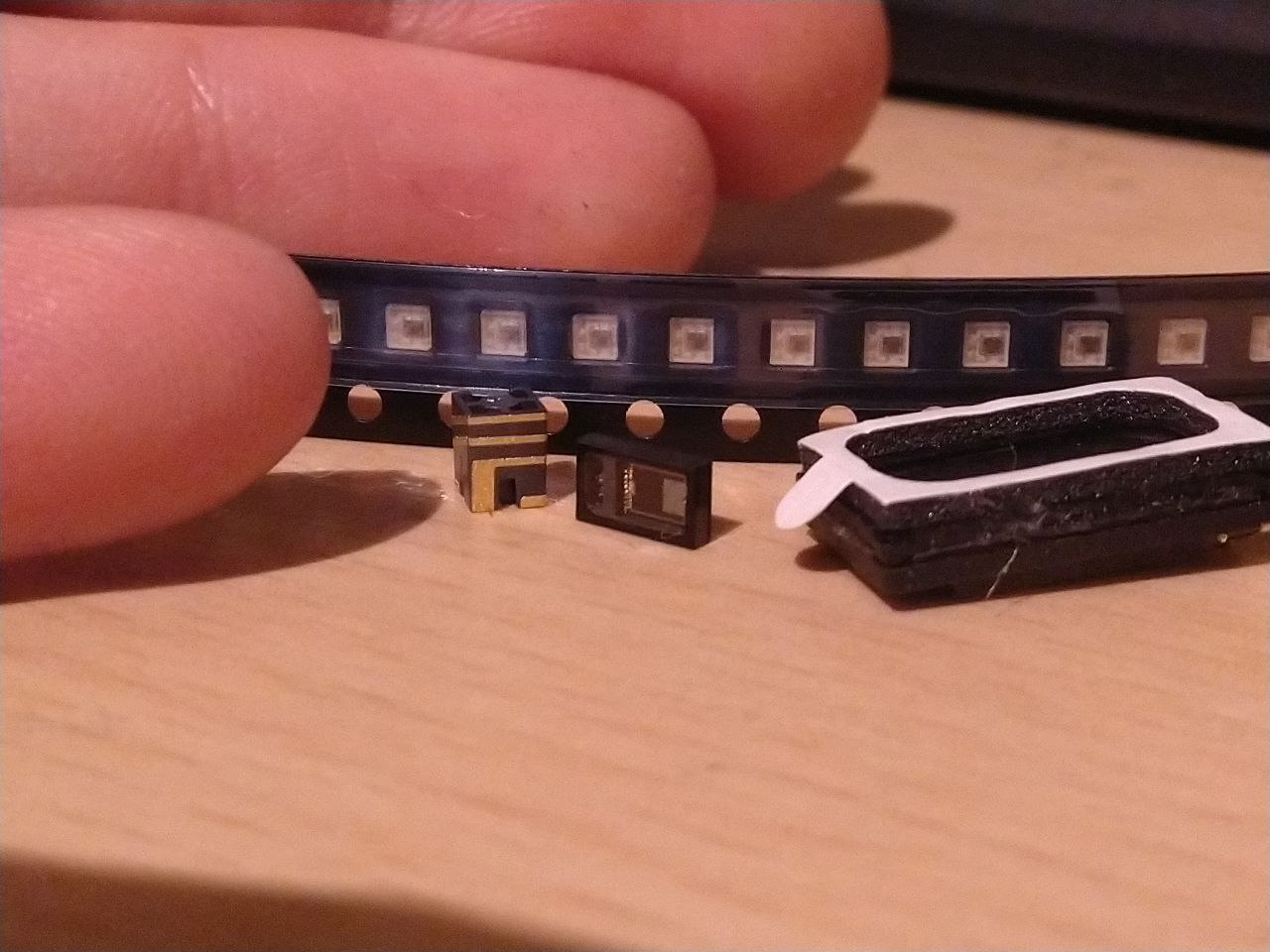
From left to right: A tiny 2.5GHz "on ground" Antenna for no ground clearance, a small PulseOximeter, a tiny speaker module, and in the back the myriads of 2x2mm WS2812-compatible LEDs (LX0707RGB). In total, the PCB BOM was about 100 EUR, but this does not include a few small sensors that were out of stock, so it would be more along the lines of 120 EUR for a full set. For a device as crammed as Tap, however, this is about right, so it was expected.
Soldering this will presumably take one whole, focused day of work. That's nothing unusual, but the small components will make it quite careful and time-consuming.
I will absolutely have to make a timelapse of the soldering process or at least the placement of the components.And definitely stick around for an upcoming video on Tap once it is all put together!
There will be a lot of features to show off, ranging from the ring of LEDs and how it can illuminate it, to the OLED screen, all the way back to the sound design and tapping and swiping based interfacing methods. -
Squishy wires
09/02/2021 at 13:57 • 0 commentsSo!
How have things gone with this project lately, you may ask? I may or may not have forgotten to add a few project logs in between... That would be my bad.
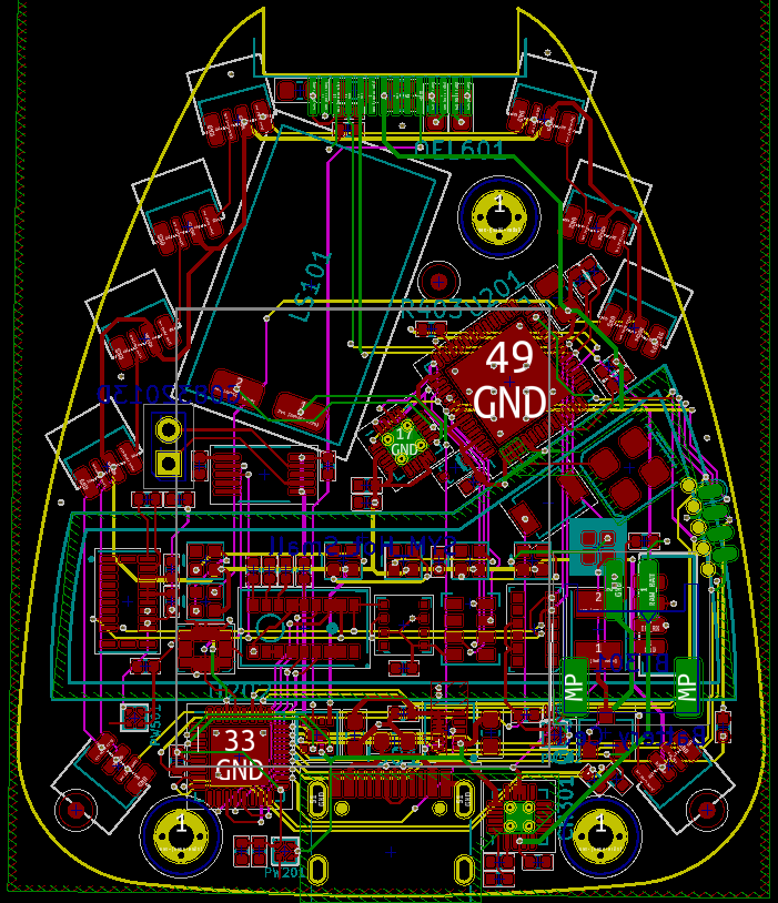
But the good news is, the PCB design is almost complete! And it is a gorgeous looking nest of wires.
Without a four-layer board design, this would have been nigh impossible, and even with the two extra layers it can be quite a squeeze! Luckily a clean, horizontal/vertical layout makes it much more headache-free. As mentioned in the previous log, the main battery charge IC had to be replaced. This was managed quite nicely, and the resulting mess of wires can be seen down below - the STM32 was squeezed in next to a USB-C port and now controls most of the power sequencing.
One of the changes resulting from further component shortage is that this STM now also includes USB connection, and the Power-Only USB-C port was replaced with a USB2.0 port. This will allow Tap to act as USB HID, and perhaps I will even utilize a fake mass storage device to write the ESP32 binaries onto the IC to update it that way?
Who knows!In any case, now that all components are fitted and most of the wiring has been completed, it is only a matter of polishing the design, double-checking tolerances, and ordering the PCB!
A lot of components are, sadly, out of stock, which will inevitably lead to a long wait on some materials. It is unclear how long it will take to actually assemble and build the badge due to this - some components are back in stock by the end of this year, some might not recover in a year, some I can leave out...
In any case, we will see when we get there.
And until then, there will be plenty of other projects to work on and polish - a rework of the Smart Home and LZRTag, a little Christmas gift, and perhaps even a simple "DIY Goto" for a Telescope we wanted to acquire :) -
Turning problems into opportunities
08/01/2021 at 17:48 • 0 commentsThere is a bit of a problem with Tap right now... Or, well, everything in general.
The chip shortage seems to have grown just a little further outward, and captured the battery charge IC that I was initially planning to use. There are alternative models, of course, but... I thought, why not try and replace it with components I am more comfortable with using. The BGA is very tricky to solder, after all.
This, however, turned out to be tricky. This single charger IC has so much functionality all in this little module:
- 1.8V LDO
- 2x Load switch
- Button reset circuit with power on/off
- ADC for battery measurement
At first I wanted to use discrete components to fill this gap, but that quickly turned into a bit of a mess, because for the button reset function alone you need three new ICs.
But... What about a separate controller? Something low powered, like an STM32L0 at low clock speed. This would be able to control the load switch, it has an ADC, and might even provide extra GPIO pins if necessary.
And then it hit me - it can do a lot more than this. It can, for example, take over the SPI slave role required to extract the camera feed of the ADPS gesture sensor, something the ESP might struggle with. It could act as battery gauge, estimating battery current over a resistor.
Best of all, it could read the ESP32's UART log output.
When the ESP crashes, it dumps a crash message to UART, which cannot be rerouted to, ex., MQTT or Bluetooth, because it's crashed. But the STM? It could happily receive the crash message, buffer it, and then write it onto the OLED screen that is built in, or send the crash message back to the ESP once it rebooted so it can be sent to a log server.
Even though STMs are in short supply and a bit more expensive, I did find that digikey still has the STM32L051 series - at 4€ in single quantity, but better than nothing.
This will, of course, take further work to program and get right, but it could elevate the badge even further.
More importantly, this STM external coprocessor could be reused in a large number of other projects to fill in some of the gaps that the ESP leaves in terms of analog, power consumption and IO pin count.
I will have to play with the idea and report back!
-
Adding some details
07/26/2021 at 21:20 • 0 commentsAnd, well, by details we mean... Everything else.
The board is both growing and shrinking - the former in the number of components that are already placed on the board, the latter in the amount of space that is still available for things.
All in all, the sensor slot has been populated pretty much completely, with only a few components left to sprinkle in such as support capacitors.
The rest of the board has also gotten models for programming, the illumination and signalling LEDs, as well as a few other components - FreeCAD has been especially helpful in the creation of missing 3D models for things such as the speaker and OLED screen.
A few components are still missing - mounting holes for the M1 screws to keep the casing together, and a little bit of passive circuitry all around.
The OLED screen might also change position a little, as currently it is quite squished in, though I always knew this would be the case.
She's looking better with every update, and with a few more hours of gently placing everything where it belongs, she's ready to order!
That is, if we can find a manufacturing service up for the task. This board features a rather large number of unusual footprints with individual parts that might throw a P&P machine off...
Input on where to get this done is greatly appreciated.
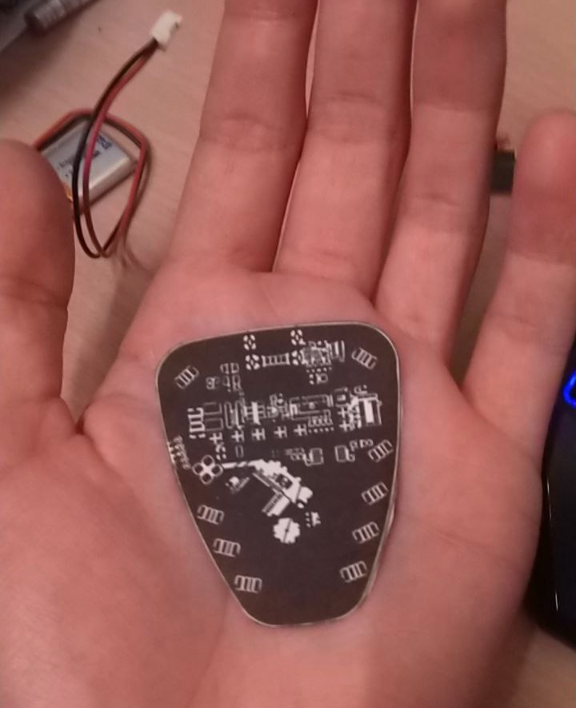
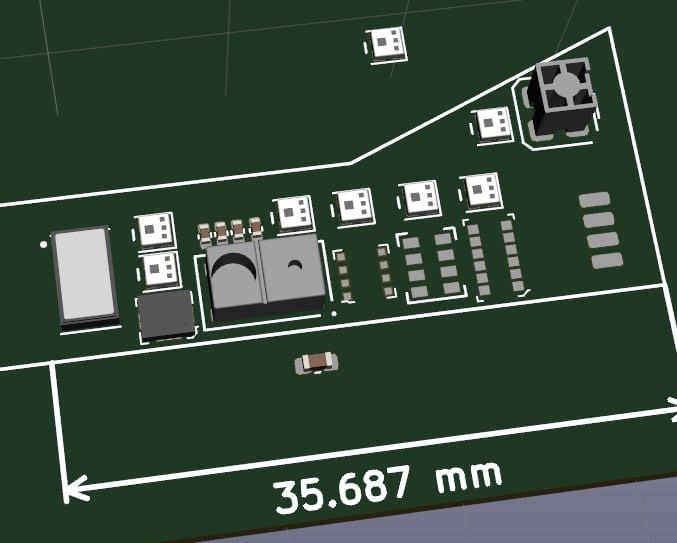
Also, for those wondering how big this PCB is in reality, here's a 1:1 scale print:
All I have to say is... Oh dear
-
Squishing the sensors
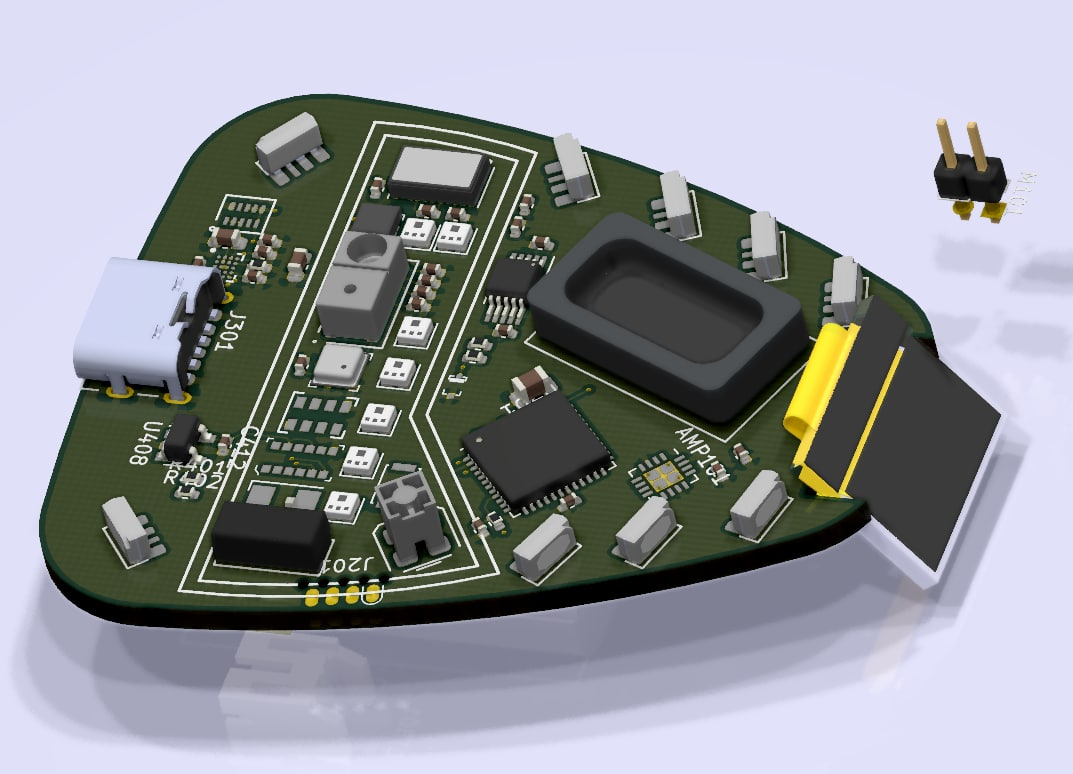
07/19/2021 at 21:23 • 0 commentsThose that look closely may see that the boundary of the sensor space looks a bit like the Mobile Emitter's cutout - you'd be right! As the description of this project already describes, TapV2's main purpose is to be a playground of various sensors and other bits of data processing. Not for any specific reason, mind you - a lot of these elements here are just sensors we'd love to try out, or that we might find useful once a year and would like to have on hand.
Some of them may even be genuinely useful!
Right now we are still in the process of squishing the sensors we already selected as close together as possible and might go ahead and add one or two more if we find them interesting enough.
Perhaps the comments could even recommend something to add to the arsenal.For now, the list is already quite capable.
Going from left to right we have:- A pulse oximeter that can measure pulse and SpO2 levels when the user places their finger on it.
- An LSM6DSM 6-axis gyro (although almost all MEMS gyros are out of stock for a few years - this one might have to be retrofitted somehow, or salvaged from another board)
- An APDS-9500 gesture sensor. Although simple looking at first, this little device sports a 60x60 pixel IR array that can act like a rudimentary camera, potentially even enough to read QR codes!
It is the main motivation for this board, and will hopefully serve us well. - A BME680 air quality sensor. Aside from the standard humidity, temperature and pressure, the 680 also reads "Volatile Compounds" that correlate roughly to how used-up the air is, and can give warnings about low air quality.
- A I2S MEMS microphone, used for simple whistle command input as well as Fourier Frequency analysis. Being able to isolate that one frequency that's annoying you should always be easy.
- And STM ToF LIDAR with about 1m range in good conditions. Not only will it replace a slide rule, it could also be used to automatically measure vibrations up to 50Hz!
The very rightmost components are for communication, such as a "On-Ground" WiFi antenna chip, and a IR module.
One last potential candidate as sensor is an ambient brightness and UV meter, to warn about excessive solar radiation, however the only part we could find for this has a big "Not recommended for new design" label across the datasheet, so it's a "maybe".
Oh, and those squares that are lined up next to every sensor module?
Those are 1.8mm sized NeoPixel clones, to illuminate each sensor's status and readouts - mainly to look flashy and interesting.Let's see how hard it is to wire everything up. There is a reason why we chose automated assembly and 4-layer boards right from the conception of the project!
 Xasin
Xasin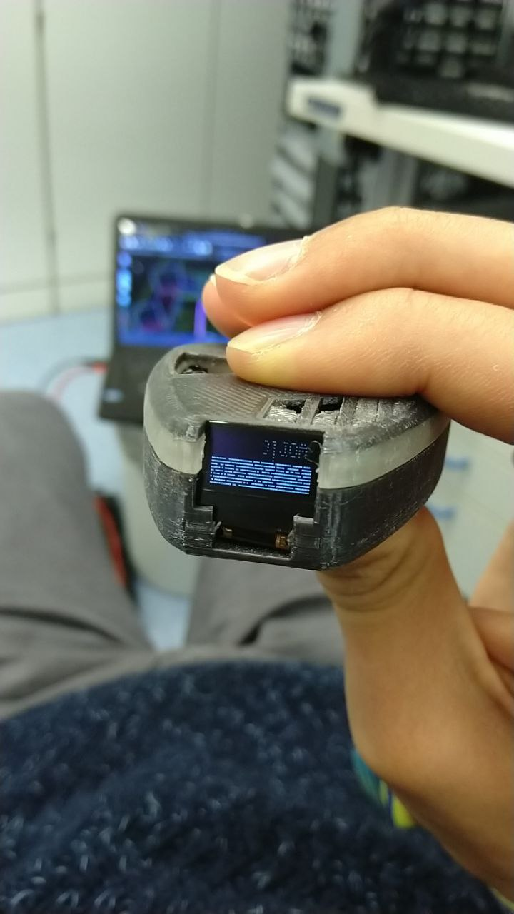


 State of the PCB