0%
0%
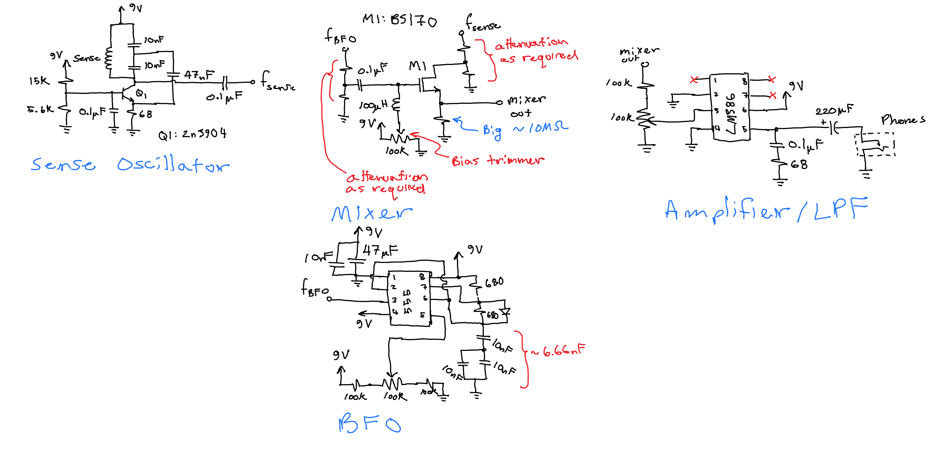
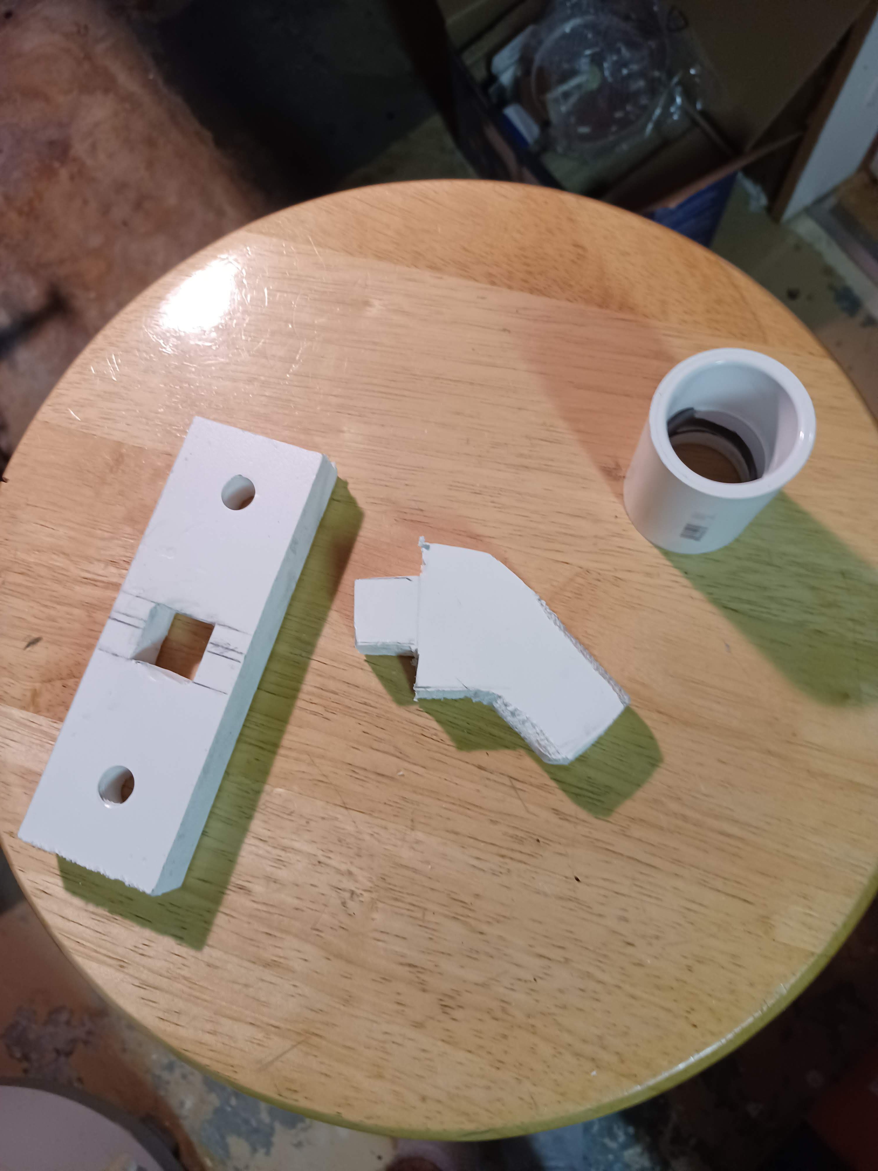
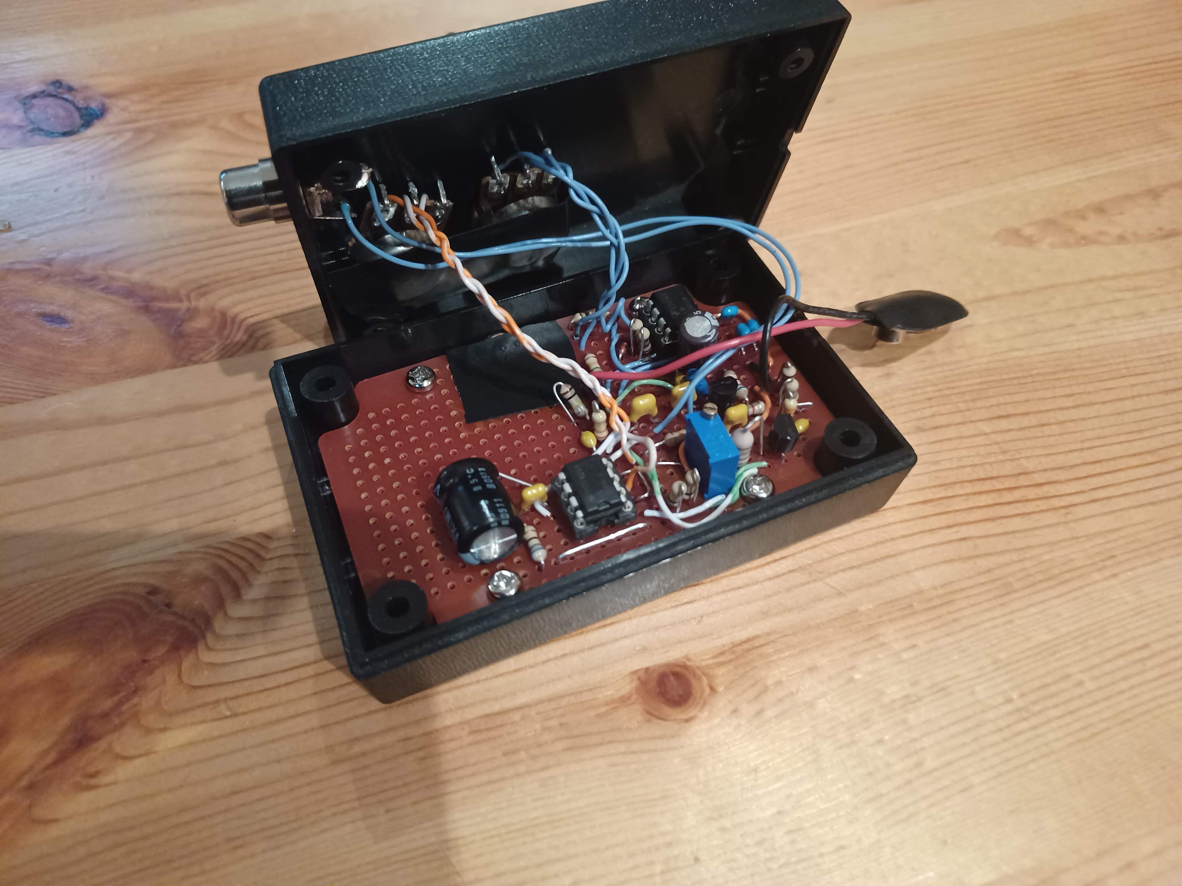
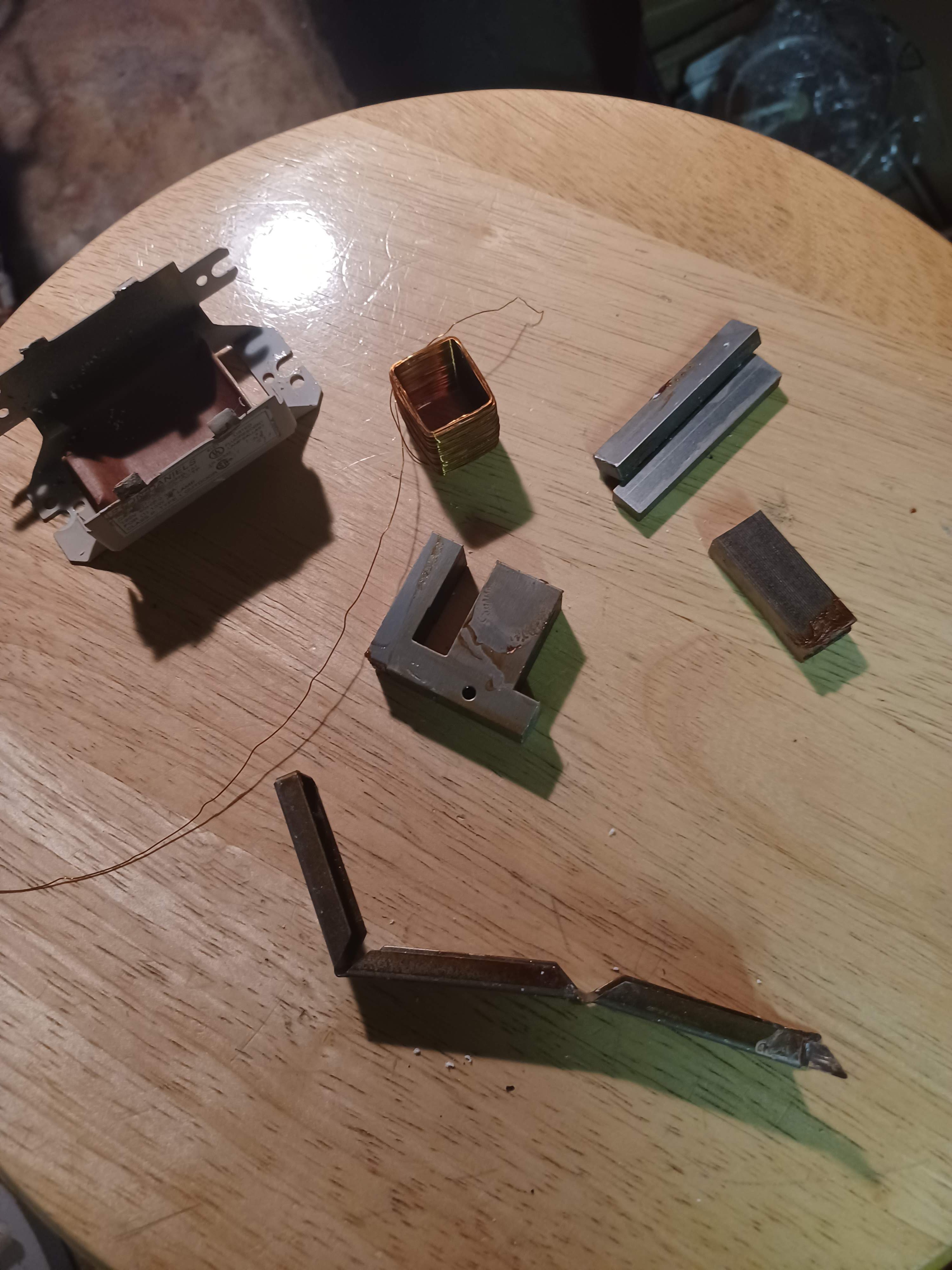
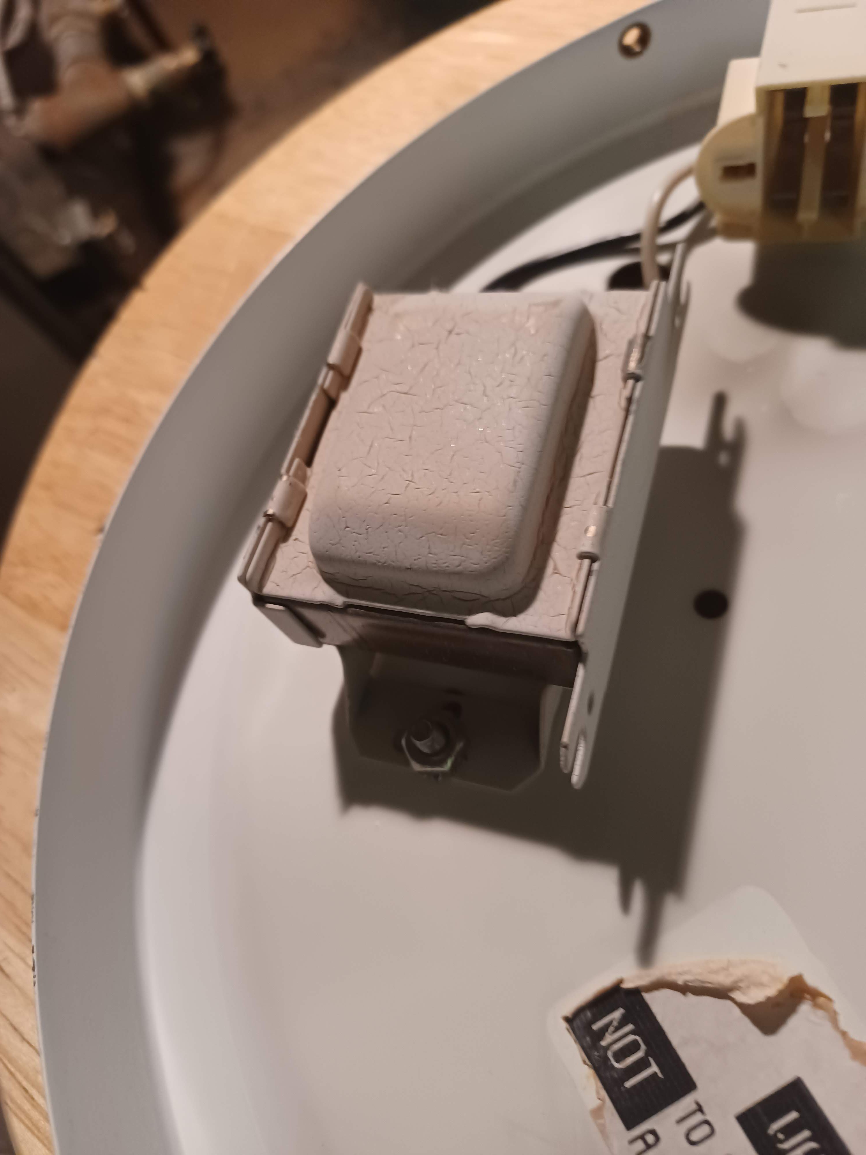
Junk Box Metal Detector
Can I build a working metal detector from what's in my junk box?
 zaphod
Become a Hackaday.io member
Already have an account? Log in.
Just one more thing
To make the experience fit your profile, pick a username and tell us what interests you.
Pick an awesome username
hackaday.io/
Your profile's URL: hackaday.io/username. Max 25 alphanumeric characters.
Pick a few interests
Projects that share your interests
People that share your interests


 Cees Meijer
 Kelly Heaton
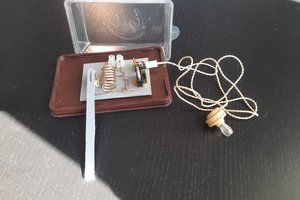
 Andrea Console
It truly encompasses a wealth of information about the subject matter.. Like
https://sassastatuscheck350.co.za/