 Timo Birnschein
Since, I don't know, 2016 or so, I have a K40 laser. I had great fun with it and learned an infinite amount about CO2 laser engraving, cutting, and got a glimpse into whatever else one can do with a laser.
The K40, at the price it comes at, needs some rather mandatory upgrades right out of the box but I won't go into those here.
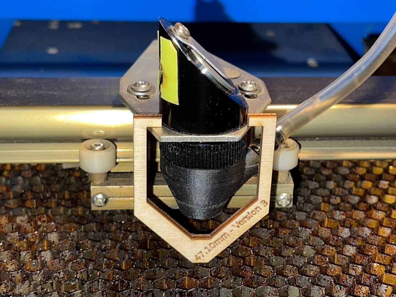
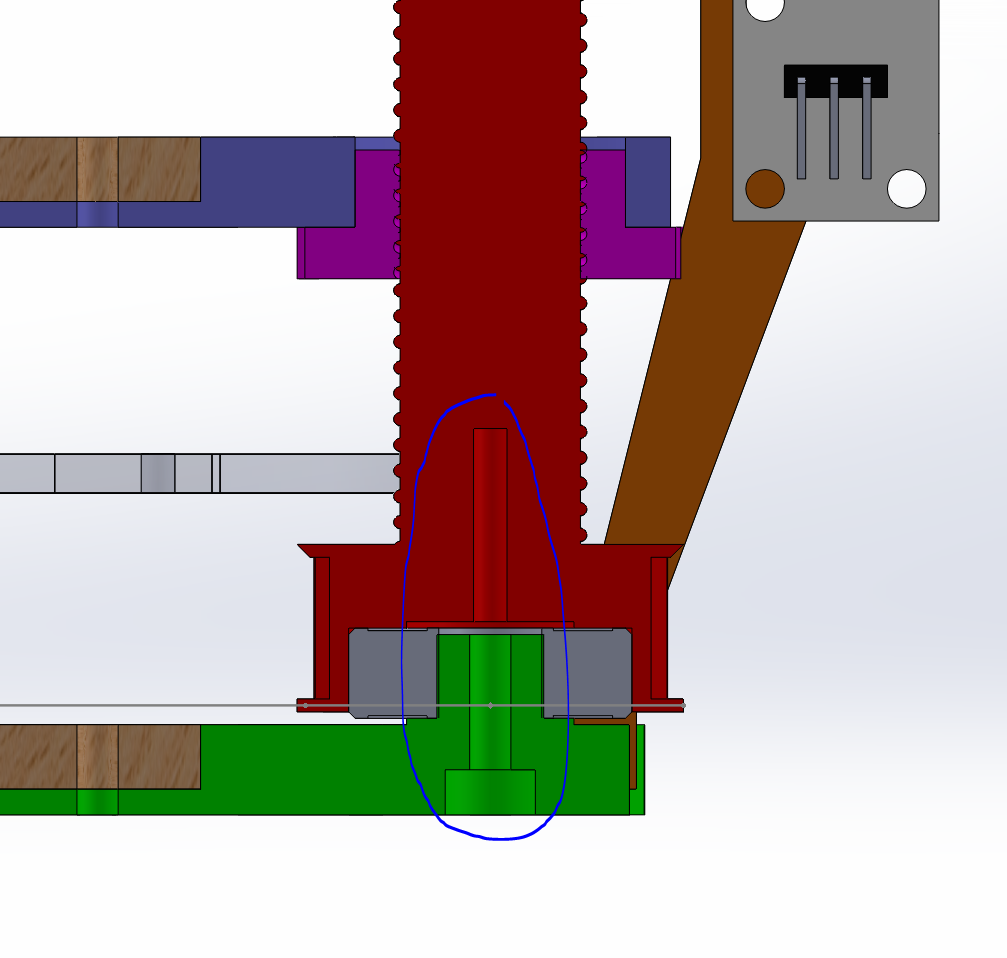
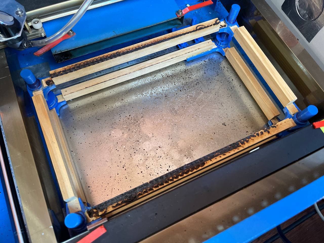
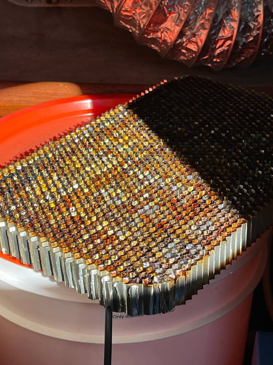
I want to concentrate on the Z-Axis, or the laser engraving platform your material rests on while it's being cut.
Shortly after I got the machine, I removed the god-awful original cutting table and replaced it with a simple construction that would just hold the work in place. I didn't want to spend the $200 on the LightObject Z-Axis Table because I didn't know how much I would end up using the thing. It looks great though!
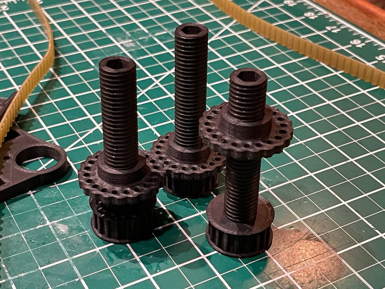
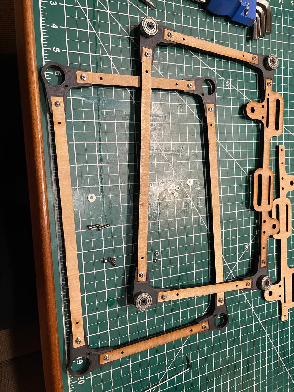
I, instead, suffered through pretty much every issue in the book of cutting until I learned enough to know where the focus point of the laser needs to be and how to get it there. However, with my first table setup that simply wasn't possible so I designed a really crappy, held together by gravity, Z-axis table that allowed me to manually adjust all four corners but not more.
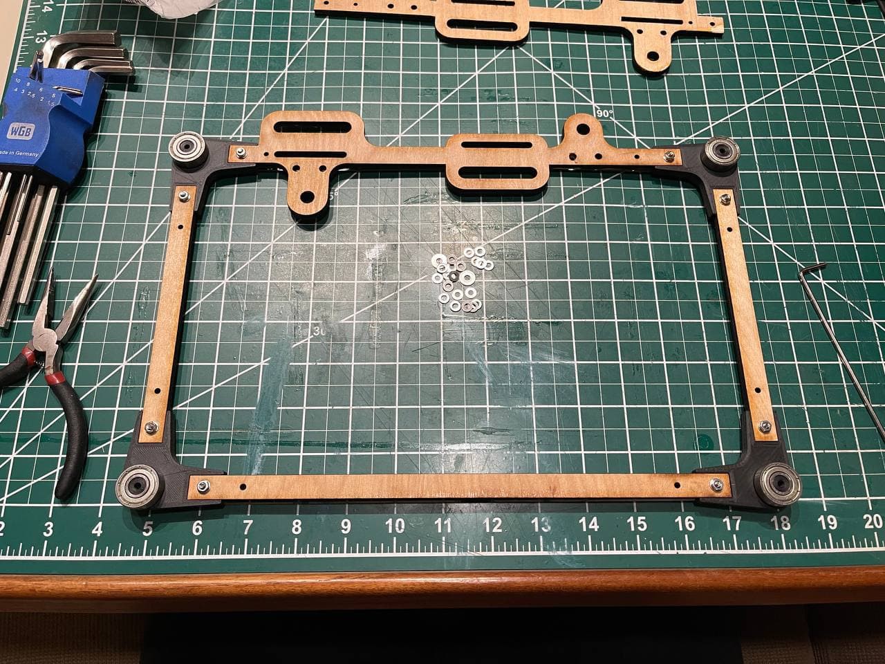
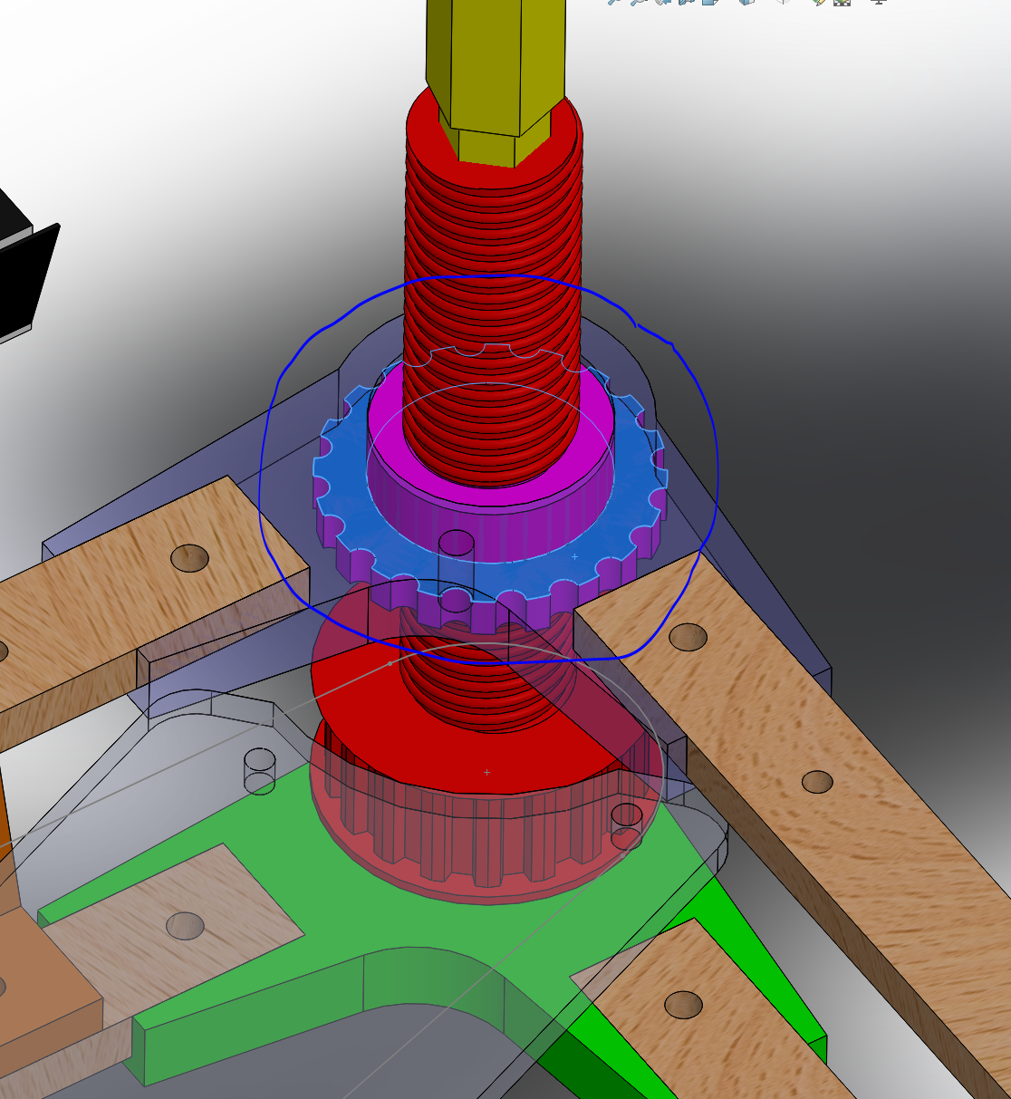
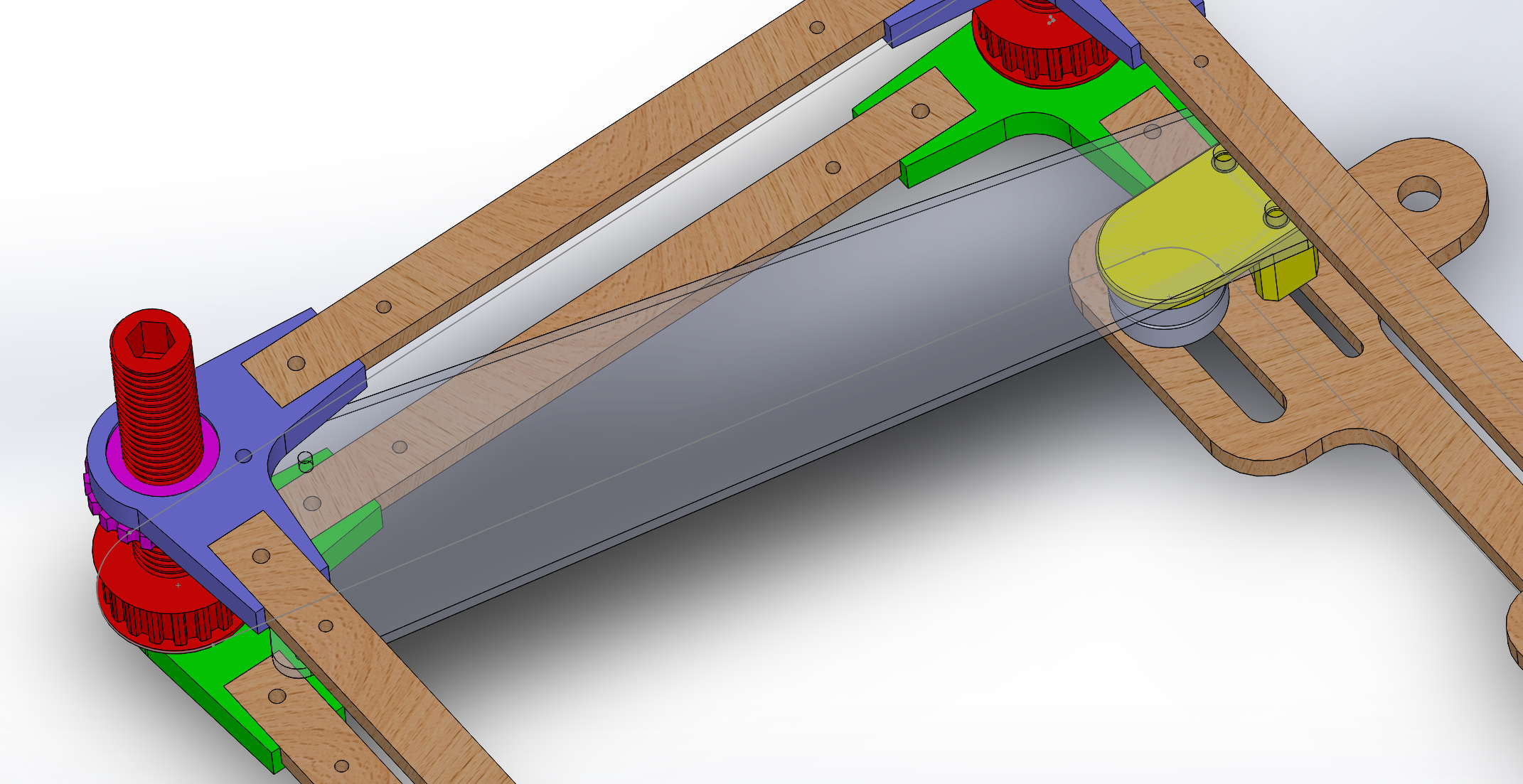
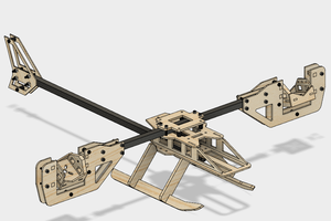
Years later, when I really needed to adjust the table to engrave something tall, it escalated quickly....
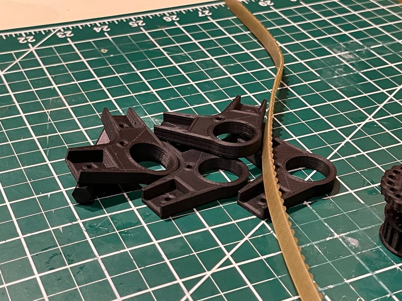

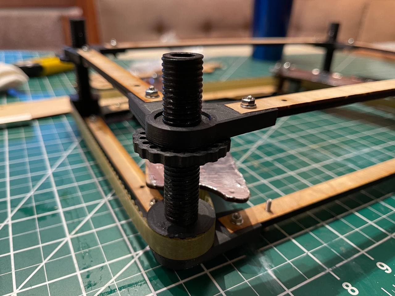
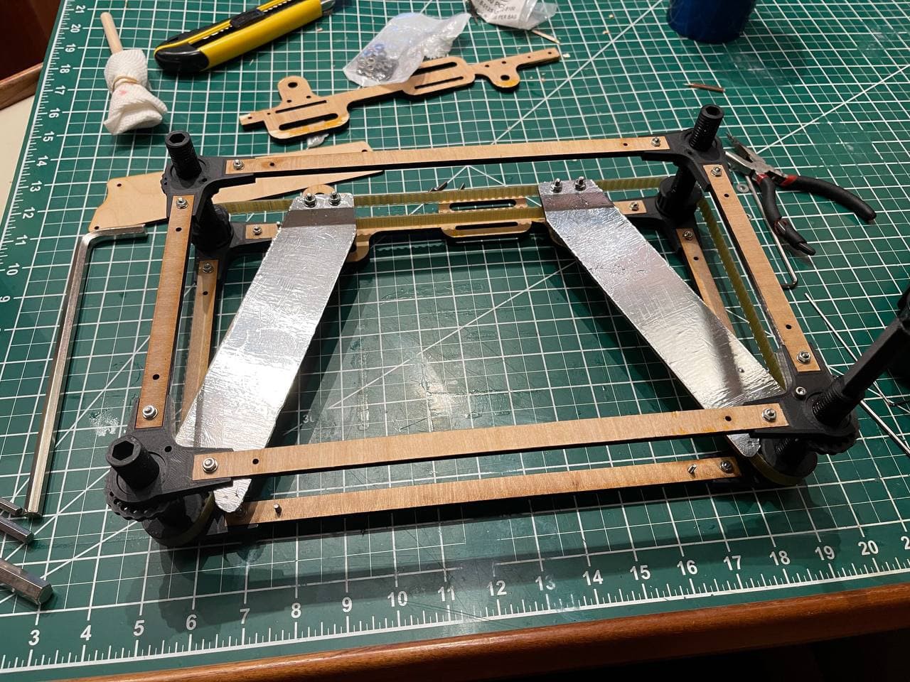
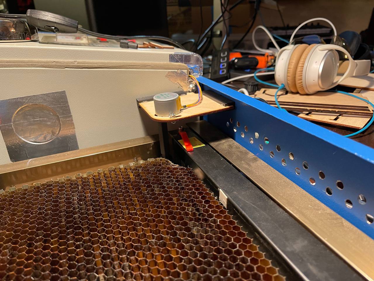
 The belt is way too thick and bending it alone causes so much friction in this design. I will attempt to redesign this to work with a short GT2 belt that can be easily purchased in the US. That will make this design more opensource compatible. Stay tuned.
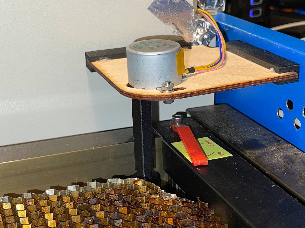
 Spencer
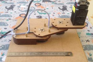
 agp.cooper
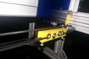
 phil
phil
 Russell Hay