 Jithin Sanal
5V – 3.3V Logic Level Shifter IC for Arduino and Raspberry Pi
Hey, Guys welcome back to RootSaid. In this post, I will show you how you can make your own 5V to 3.3V logic Shifter for connecting 5V sensors to new Arduino Boards and Raspberry Pi.

Why do we need a Logic Level Shifter IC?
Most of you love playing with Arduino and Raspberry Pi during your free time right? Of Course, that’s what hobbyists do!
Along with Arduino, we will definitely use various sensors such as IR sensor, PIR sensor, and Ultrasonic sensor. But the problem is most of today’s boards are not 5 V tolerant and almost all of the boards work under 3.3V.
Does that mean we can't use our old sensors anymore?
Not exactly. Almost all of the microcontrollers work under 3.3V logic these days. Most of the devices that work under 3.3V do not like being provided with 5V and will get burned in seconds. So what can we do about it? Luckily, there is a way, there are logic level shifters that will convert 5V to 3.3V. One such IC is 74LVC245.
74LVC245 Logic Level Shifter IC
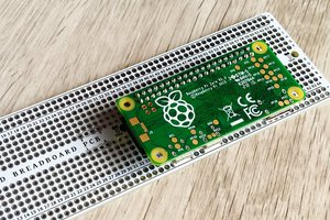
This chip solves the problem of connecting and sending data from 5 V logic level devices to 3.3 V logic microcontrollers such as Raspberry Pi and Arduino. This chip stands in between Arduino and the Sensor and converts the 5V signals from the sensor to 3.3V which can be directly fed to Arduino.
74LVC245 can be used with digital signals and works great with SPI, Serial, Parallel bus, and other logic interfaces.
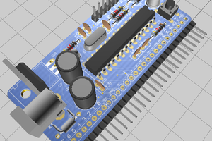
Designing the Circuit 74LVC245 Logic Level Converter IC
I used Altium Designer to draw the circuit and design the PCB. It is a powerful tool that can be used to design and create your own PCBs for your project as well as complex and multiplayer PCBs for industrial use. Here is the link to the Altium trial version. So make sure you check it out.

Working with this IC is pretty simple. You can set up the circuit in a matter of minutes.
- Simply connect VCC to your logic level you want to convert to. If you are converting 5V to 3.3V, connect 3.3V to VCC.
- Ground connects to Ground.
- OE (output enable) to ground to enable the chip
- DIR to VCC (3.3V).

Once you have finished drawing the circuit, save the circuit by clicking save and creating the PCB layout.
Getting PCB Done
I ordered PCB from PCBWay. PCBWay is a PCB manufacturer specializing in PCB prototyping, low-volume production, and neat and tidy PCB assembly.

To order your PCB from PCBWay, go to the PCBWay website and fill in the basic board details in the instant order form. From there you will be directed to a form where you can provide more elaborate board details. Update your board information in the PCB specification screen. On the next screen, you should be able to upload your Gerber file and submit it for review. Once the review is completed, all that is left is to add to the cart, make payment, and wait for your PCBs to arrive.
Once you get all the components and the PCB, it’s time for you to solder them together. Solder all the components onto the board and make sure to check the polarity of the components. After soldering the PCB looks like this.
I personally find soldering on this kind of PCBs a fun task, because of these pads soldering becomes very easy. The solder takes up the conical shape and gets soldered from all the sides evenly. After soldering the PCB looks like this.
This is the assembled board. Neat and Clean. Once you get the board, you can take one and solder the remaining components into it. I have soldered the header pins and this is the finished board.
Testing the 5V to 3.3V Logic Level Shifter
Now if you connect the 5 V Signals at A Pins, you will get 3.3 V at corresponding B Pins.

Now we will check that by connecting a 5V in A1 and 0V in A5
So this will give 3.3V Out at B1 and 0V at B5.

 Simon
Simon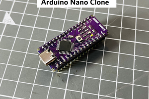
 Lithium ION
 Clovis Fritzen