 Clovis Fritzen
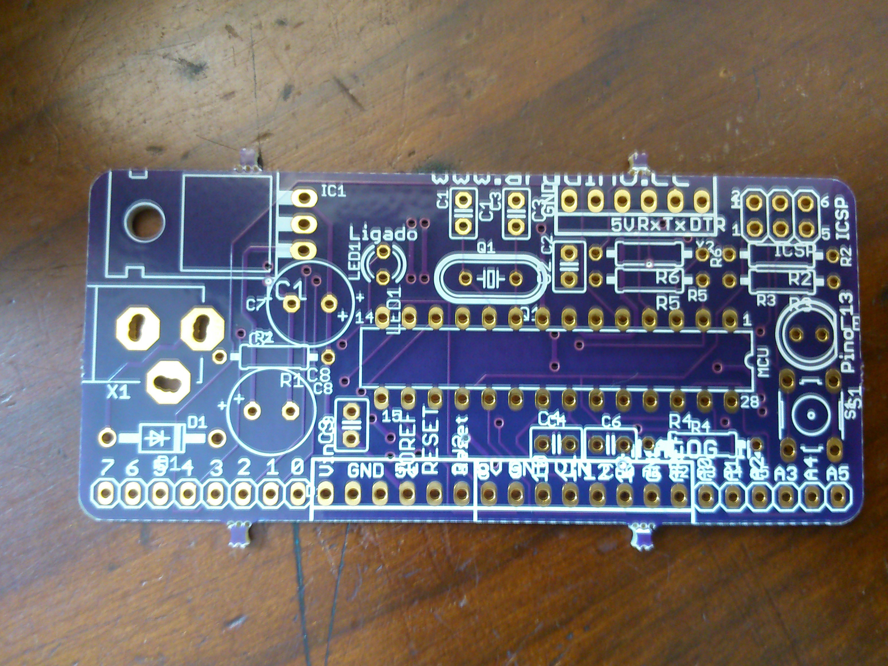
Basically what I did was download Arduino UNO design files from the Arduino.cc website and strip down all parts and circuits I didn't need; I also replace most parts for similar/compatible ones from Adafruit/SparkFun/SeeedStudio Eagle CAD libraries.
My final goal was to creat an all-Through-Hole (TH) board that could be assembled by virtually anyone with a soldering iron and some will to do it.
The result of this work would be (I tought) an Arduino-compatible (vertically)- attachable prototipying board for breadboards or final products.


 Pratik Makwana
 Simon
Simon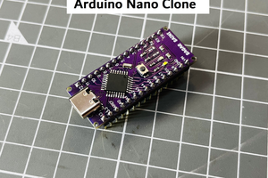
 Lithium ION
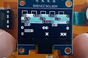
 ElectronicABC
I just received your board. I see that there are five components listed and I know where on the board they go but the board contains many other connections for other components. What are they for? Can I leave them disconnected?