Close
0%
0%

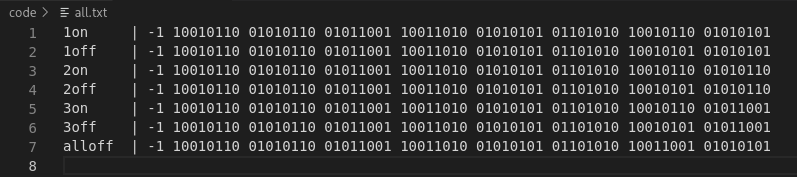
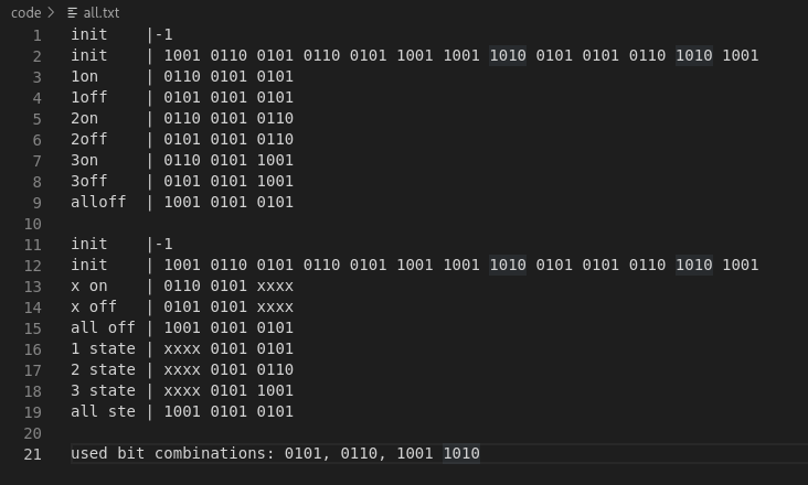
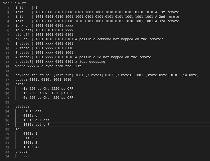
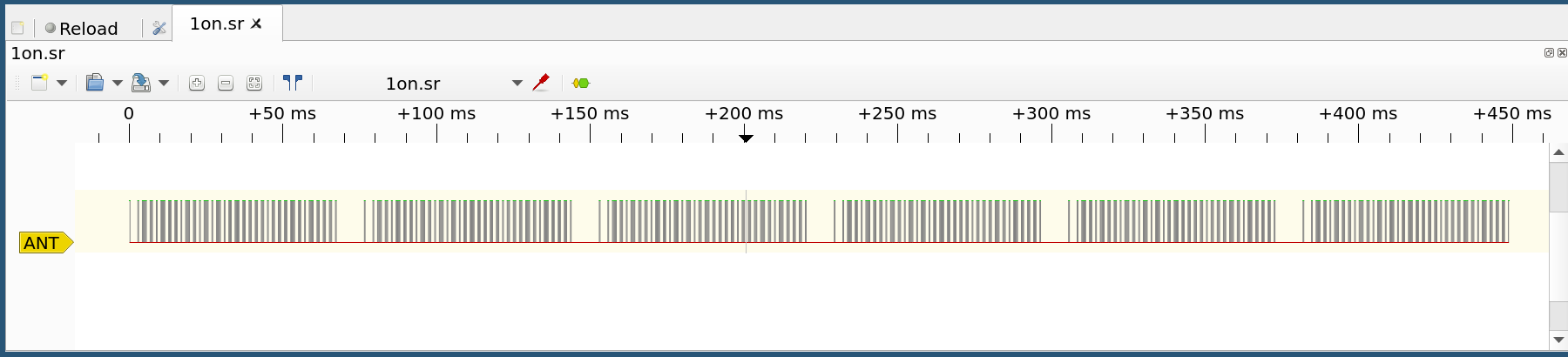
Reverse engineering wireless plugs

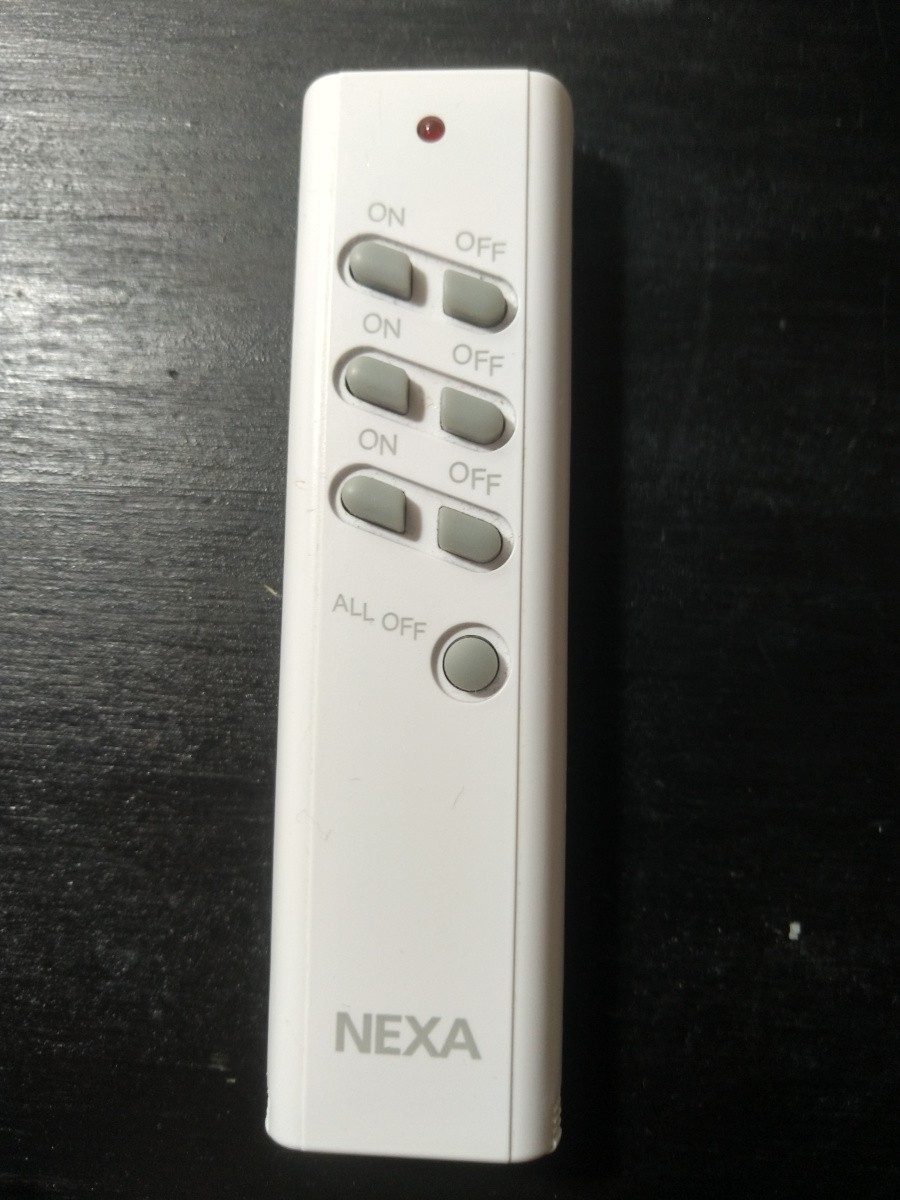
Attempt to control Nexa MYCR-1000 wireless plugs with Raspberry Pi

Similar projects worth following
This is an attempt to control wireless plugs through a Raspberry Pi. At first I will capture the remote signal, then make my own remote using cheap 433MHz transmit modules which will be controlled with the Raspberry Pi GPIO pins
  • 8. A working firmware for the Attiny85

    suikale03/22/2022 at 15:57 0 comments

    The previous code I wrote worked perfectly fine if the Raspberry Pi would send just one byte containing critical information to the Attiny85. However you can just cram so little information to 8 bits. When trying to send two or more bytes everything failed, and it took me ages to figure out why. The short answer to this question is timings.

    At first when the Attiny received data it had no way of knowing if it would receive 1 or more bytes. It would just cram everything it received into a FIFO buffer. But the write operation to that buffer was so slow that it would not keep up with the SPI bus. Data would get corrupted because the previous interrupt caused by the SPI write was not over when the new one would begin. This was the most infuriating part to debug without using GDB (yeah, I'll need to learn how to use that properly) only with just a logic analyser. To overcome this problem I had to lower the SPI frequency from 2MHz to 250 KHz.


    Then I encountered another problem. The Attiny would start unloading the buffer before all the data was written to it. So then I had to learn about the hardware timers and how to use them to delay the buffer unloading operations a bit. At the moment the Attiny waits 0.13056 seconds before it looks into the buffer. (calculated with p * t * 1 / f, where prescaler = 1024, timer count = 4*255, frequency = 8000000). It works fine when receiving 1 to 5 bytes, but fails with more. So I'll need to find out a better way to trigger the interrupt that launches buffer handler.

    But now the code works perfectly in this usecase. You can emulate all the 4^13 different remotes and hardcode in your bought remotes. All the devices, states and groups work as expected. Also while testing and pondering the logic behind my code I foud out that I made a mistake while pentesting the differences with Klik aan Klik uit and Nexa codes. The payloads sent by the remotes might be the same, but the timings differ so much that the KaKi code does not work with the Nexa devices without adjusting the timings.

    Now I'll need to write a controller to send the necessary bytes from the Raspberry Pi side to the Attiny.

  • 7. Tests with Attiny85

    suikale02/21/2022 at 15:30 0 comments

    I modified the test code to work with an Attiny85

    #include <avr/io.h>
    #define ANT_PIN PB3
    
    int main(void)
    {
        // set ANT_PIN as output
        DDRB |= (1 << ANT_PIN);
    
        for (int i = 0; i < 10000000; i++)
        {
            PORTB |= (1 << ANT_PIN);  // high
            PORTB &= ~(1 << ANT_PIN); // low
        }
        
        return 0;
    }

    I flashed the IC with Raspberry Pi, and captured about 30 seconds of data from the antenna pin.

    Analyzing a few million lines from the captured data shows all of the state changes are now between 1 and 3 microseconds. There is a bit of fluctuation but less than the original remote has

    $ cat attiny.txt | awk '{if ($2 > 3) {print $0}}' | wc -l
    0
    
    $ cat attiny.txt | head -n 10
    time:    2.875000 µs, state: 0
    time:    1.375000 µs, state: 1
    time:    2.750000 µs, state: 0
    time:    1.375000 µs, state: 1
    time:    2.875000 µs, state: 0
    time:    1.375000 µs, state: 1
    time:    2.875000 µs, state: 0
    time:    1.375000 µs, state: 1
    time:    2.750000 µs, state: 0
    time:    1.375000 µs, state: 1
    

    After changing a few lines from the main code I could capture the "1 ON" -signal. It looks exactly like from the original remote. After switching the logic analyzer for an antenna it turns on the plug every single time

    Now it's time to write some code to make the IC behave more like a remote control rather than spamming just one signal

  • 6. Raspberry Pi capabilities

    suikale02/19/2022 at 10:02 0 comments

    To test the RPi GPIO delays I used this short code

    #include <pigpio.h>
    
    int main(void)
    {
        gpioInitialise();
        gpioSetMode(2, PI_OUTPUT);
    
        for (int i = 0; i < 10000000; i++)
        {
            gpioWrite(2, 1);
            gpioWrite(2, 0);
        }
    
        return 0;
    } 

    The compiled program ran on Pi Zero with no other programs on the background. Output was captured with the logic analyzer and it doesn't look so good

    I ran the parser on the captured output writing precise timings to a file, this snipper shows average output

    time:    0.125000 µs, state: 0
    time:    1.000000 µs, state: 1
    time:    0.125000 µs, state: 0
    time:    0.250000 µs, state: 1
    time:    0.125000 µs, state: 0
    time:    0.250000 µs, state: 1
    time:    0.125000 µs, state: 0
    time:    0.250000 µs, state: 1
    time:    0.125000 µs, state: 0
    time:    0.125000 µs, state: 1
    time:    0.250000 µs, state: 0
    time:    0.125000 µs, state: 1
    time:    0.250000 µs, state: 0
    time:    0.125000 µs, state: 1
    time:    0.250000 µs, state: 0
    time:    0.125000 µs, state: 1
    time:    0.250000 µs, state: 0
    time:    0.125000 µs, state: 1
    time:    0.250000 µs, state: 0
    time:    0.125000 µs, state: 1
    time:    0.250000 µs, state: 0
    time:    0.125000 µs, state: 1
    time:    0.250000 µs, state: 0
    

    This doesn't look so bad. But when sorting the output you'll start to notice that the output is not stable. At most the delay is about 4300 times more than expected.

    $ cat capture.txt | awk '{if ($2 > 100) {print $2}}' | sort -n
    101.000000                                                                     
    104.125000
    105.875000
    107.125000
    108.375000
    109.250000
    109.500000
    110.500000
    110.875000
    112.750000
    114.625000
    114.750000
    115.250000
    115.625000
    117.750000
    120.250000
    121.500000
    122.000000
    122.750000
    123.500000
    133.375000
    142.125000
    146.875000
    148.625000
    149.250000
    149.375000
    149.875000
    194.250000
    200.625000
    207.625000
    230.625000
    236.125000
    236.500000
    269.875000
    351.750000
    445.500000
    451.500000
    538.625000

    And this is on an idle Pi Zero (load avg 0.09), imagine the delays on a Pi with more load. It could work sometimes, but I need to trust that the remote works without failures more than 99% of time. Looks like the remote needs a separate microcontroller.

  • 5. Sending the bits

    suikale02/18/2022 at 09:41 0 comments

    I wrote some C code to test the Raspberry Pi capabilities. For now it is hardcoded to send ON to first device of first remote I used. There's two versions, other uses bits like I initially thought they would be and the other uses shorter KaKu-like bits.

    Capturing the data with a logic analyzer shows it sure looks a lot like the data captured from original remote control. There is no noticeable differences between the two versions, so I'll stick to the first one. However analysing the data with remote payload parser there seems to be something that does not look promising. This is a snippet from a random range showing the precise time spent in each state.

    time: 1089.000000 µs, state: 0
    time:  340.500000 µs, state: 1
    time:  287.000000 µs, state: 0
    time:  286.250000 µs, state: 1
    time: 1090.625000 µs, state: 0
    time:  340.125000 µs, state: 1
    time:  290.375000 µs, state: 0
    time:  285.000000 µs, state: 1
    time: 1089.750000 µs, state: 0
    time:  338.375000 µs, state: 1
    time: 1086.250000 µs, state: 0
    time:  283.500000 µs, state: 1
    time:  282.125000 µs, state: 0
    time:  280.250000 µs, state: 1
    time:  286.125000 µs, state: 0
    time:  282.000000 µs, state: 1
    time: 1087.875000 µs, state: 0
    time:  284.000000 µs, state: 1
    time: 1086.625000 µs, state: 0
    time:  284.625000 µs, state: 1
    time:  282.250000 µs, state: 0
    time:  280.750000 µs, state: 1
    time:  297.875000 µs, state: 0
    time:  282.500000 µs, state: 1
    time: 1085.000000 µs, state: 0

    It is not consistent enough. The pulse lengths should be about 250, 1250 and 2500 microseconds. Even after I changed the delay in code to 200 µs the variation is between 260 and 380 µs for the shortest pulse. Longer delays should be 1000 µs, and it does not vary so much as the shorter pulse. I switched the logic analyzer to a 433MHz antenna and the code worked only on about every fourth attempt. Spamming the payload more than 6 times may work, but it does not seem trustworthy. The Raspberry Pi GPIO pins might not be accurate enough for sub-millisecond scale delays.

  • 4. Comparing Nexa and Klik aan Klik uit

    suikale02/17/2022 at 17:48 0 comments

    Recently the project got a comment about similar looking plugs from a dutch company called Klik aan Klik uit. The plugs could be controlled with this Arduino library. So I did a comparison between my findings for Nexa and the KaKu Arduino code.

    First, these are my latest notes on Nexa plugs. I changed the payload structure a little bit based on this comparison. The timings are also rounded a bit more.

    payload structure: 
        [init] 1001 [7 bytes] 0101 [3 bytes] 1001 [state byte] 0101 [id byte] # first quess
        [init] 1001 [11 bytes for remote id] 1001 [state byte] [group bits] [id byte] # refined quess
    
    bytes: 0101, 0110,    1001,   1010
    state:  off,   on, all off, all on
       id:    0,    1,       2,      3
    group:    0,    1,       2,      3
    
    bits:
     init: 250 µs ON, 2500 µs OFF 
        1: 250 µs ON, 1250 µs OFF
        0: 250 µs ON,  250 µs OFF

     After analysing the KaKu code I was able to extract this information

    kaku payload structure (without dimmer):
        [syc] [32 bits]
        where:
            syc is roughly the same as nexa init 
            32 bits are ((id<<6|dev)|state<<4)|(group)<<2
            
            0000iiii iiiiiiii iiiiiiii ii000000 | between 0 and 4194303
                                       00e000dd | e = 1, dd = 00 for every device, else dd = 00 - 11
                                  0000 000s0000 | 1 or 0
                                  0000 0000gg00 | 00 - 11
        ->  0000iiii iiiiiiii iiiiiiii iiesggdd | full payload
    
    ->  payload: [syc] [0000iiii iiiiiiii iiiiiiii iiesggdd]
    
    kaku bits:
      syc: 10810 µs OFF, 230 µs ON, 2760 µs OFF 
        1: 230 µs ON, 1380 µs OFF, 230 µs ON, 322 µs OFF
        0: 230 µs ON, 322 µs OFF, 230 µs ON, 1380 µs OFF
       -1: 230 µs ON, 322 µs OFF, 230 µs ON, 322 µs OFF # used in dimmer payload only
    
    kaku states:
         0: off
         1: on
    100000: control group instead of single device
    
    kaku id and group:
        00: 0
        01: 1
        10: 2
        11: 3

    The bits  and timings look surprisingly similar. To make the comparations easier I had to do some translations

    kaku bits to nexa bits:
        kaku | nexa
         syc | init
          1  |   10
          0  |   01
    
    comparing: 
    kaku payload translated to nexa bits:
        [init] 0101 0101 [44 id bits] [2 whole group bits] [2 state bits] [4 group bits] [4 device bits]
    nexa payload:
        [init] 1001 [44 id bits] 1001 [4 state bits] [4 group bits] [4 device bits]
    
    kaku payload: 
        [syc] 0000iiii iiiiiiii iiiiiiii iiesggdd
    nexa payload translated to kaku bits:
        [syc] 10iiiiii iiiiiiii iiiiiiii 10ssggdd

    So there are some subtle differences in timings and payload structures. I will test this more when I get some working hardware to send these payloads.

  • 3. Parsing the data

    suikale02/15/2022 at 08:32 0 comments

    Step 1: All of the the payloads grouped in to a single file. Then I separated the initial pause and 64 bits that follow, grouped by 8 bits. Notice some similarities. The first 52 bits after the initialisation are the same on each command

    Step 2: Further dissection shows some more patterns starting to emerge

    Step 3: Repeat the same process for two more remotes all of which are in different groups. The product packaging says theres 32 different memory slots so there's possibly 4 IDs and 8 groups?

  • 2. Trying to parse the data

    suikale02/14/2022 at 18:57 0 comments


    Step 1: Take a look at the data on Pulseview. There are 6 blocks of similar looking values.


    Step 2: I wrote a quick Python script to tell time spent on each state. Notice that the values are roughly 250 µs, 1250 µs, 2550 µs and 9150 µs

    Step 3: This is a single data block which length is about 68 ms. Seems that the payload structure is 250 µs ON, 2550 µs OFF for initialiser bit. After that comes series of bits which are 250 µs ON, 250 µs OFF (or HIGH to LOW and 250 µs pause) for 0 and 250 µs ON, 1250 µs OFF (or HIGH to LOW and 1250 µs pause) for 1. Lets call the longer states -1 for now.

    Step 4: Quick rewrite of the parser shows we are getting some decoded data.

    Step 5: It is also easier to see that the payload is 65 bits transmitted 6 times in a row with a ~10ms pause in between

    Step 6: Changed two lines from the parser and now we have a bit presentation of the payload. -1 is the longer initial bit, 1 and 0 are described above

  • 1. Capturing the remote signals

    suikale02/14/2022 at 11:36 0 comments

    Step 1: Open the remote


    Step 2: Use electical tape to secure the battery and buttons to the PCB leaving the main IC exposed. It is not required to identify the IC, but it would help with the complete reverse engineering process

    Step 3: Attach a logic analyzers digital pins to the IC. Order of the wires doesn't matter

    Step 4: Setup Pulseview, start capture and press each of the remote keys. 8MHz is a good quess for initial frequency. D0 is IC pin 1, D7 is IC pin 8 and so on

    Step 5: Label the pins and figure out what the pins are used for. BTN1 is for capturing 1st row of buttons, BTN2 for 2nd row and "All off" -button, BTN3 is for 3rd row. ANT is for the data sent to antenna. D3 and D5 are used for differentiating key presses for each BTN line and they are not needed here

    Step 6: Try to decode the signals using Pulseviews decoder selection. Since the every decoder I tried give garbage data lets treat the signal as unknown proprietary data

    Step 7: Save the unmodified data. Delete all other lines but ANT. Add markers sandwitching out only the essential data. Save each label range as separate .sr file

    Step 8: We now have isolated the data that needs to be sent through the homemade transmitter to seven different .sr files

View all 8 project logs

  • 1
    Open the remote
  • 2
    Prepare the board for logic analyzer

    Use electical tape to secure the battery and buttons to the PCB leaving the main IC exposed. It is not required to identify the IC, but it would help with the complete reverse engineering process

  • 3
    ​Attach a logic analyzers digital pins to the IC

    Order of the wires doesn't matter. Use of a test clip is highly recommended but soldering the wires works also

View all 7 instructions

Enjoy this project?

Share

Discussions

Christian wrote 02/18/2022 at 12:45 point

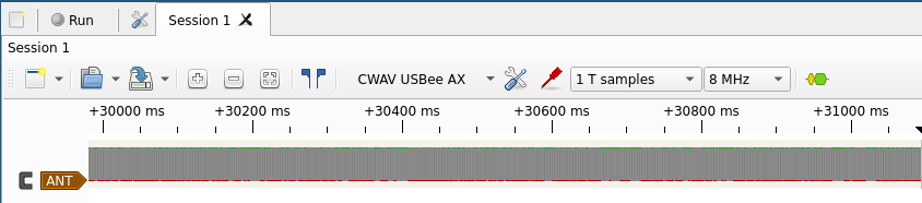
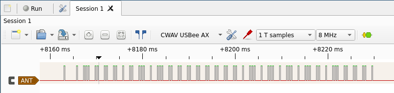
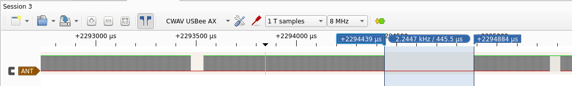
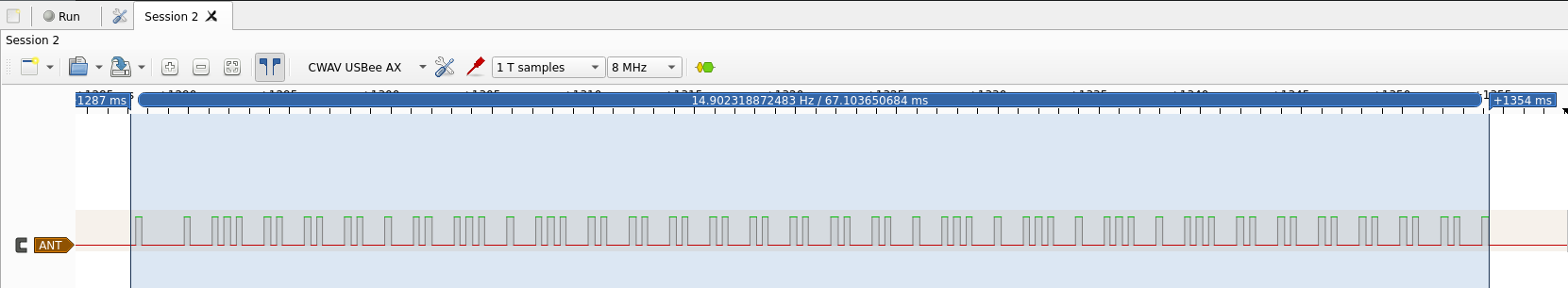
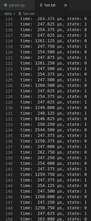
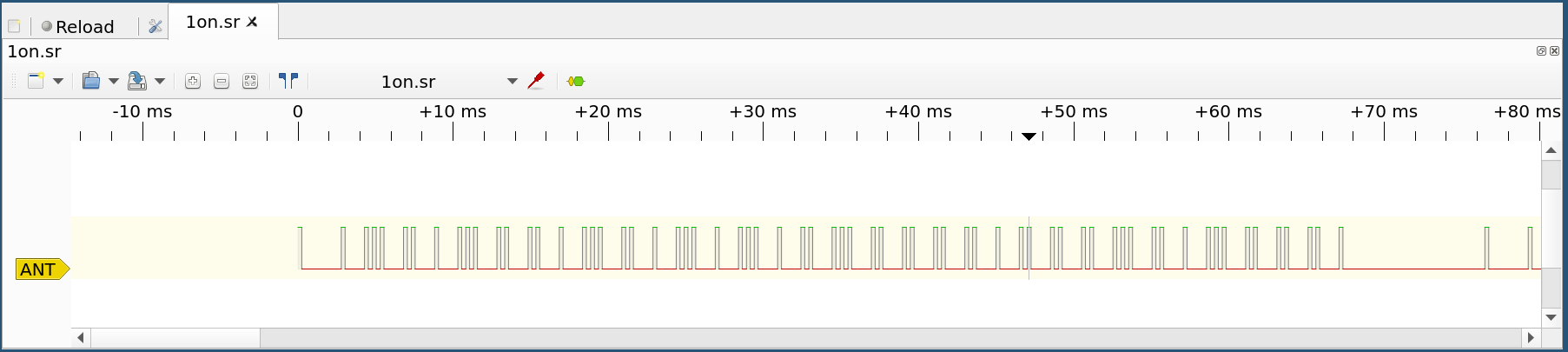
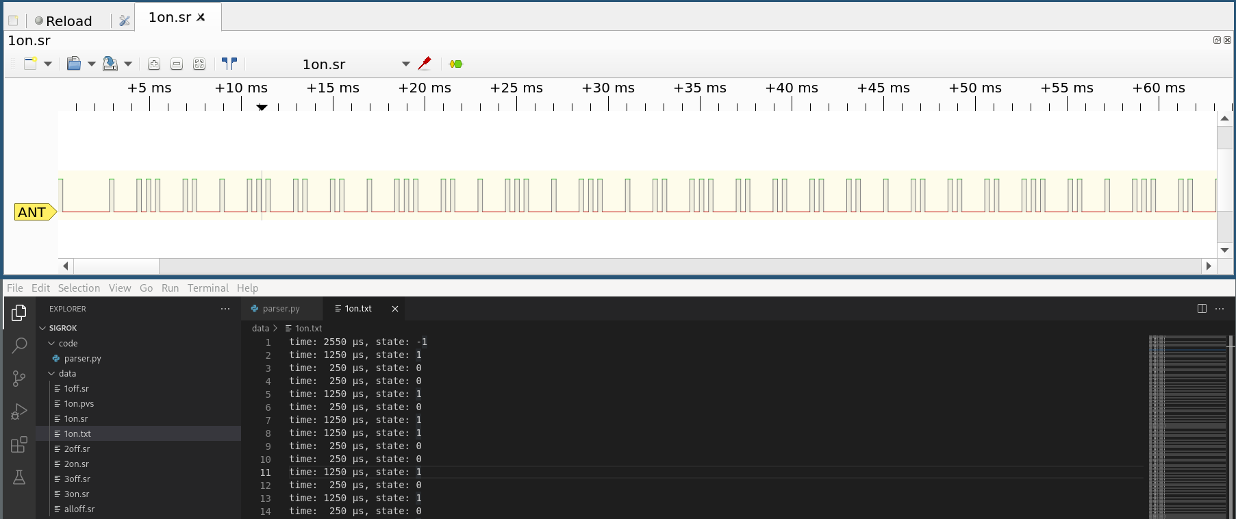
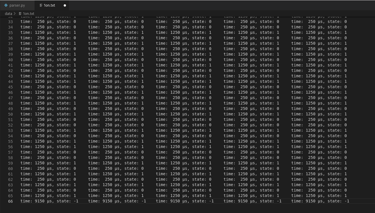
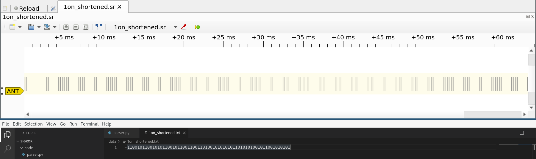
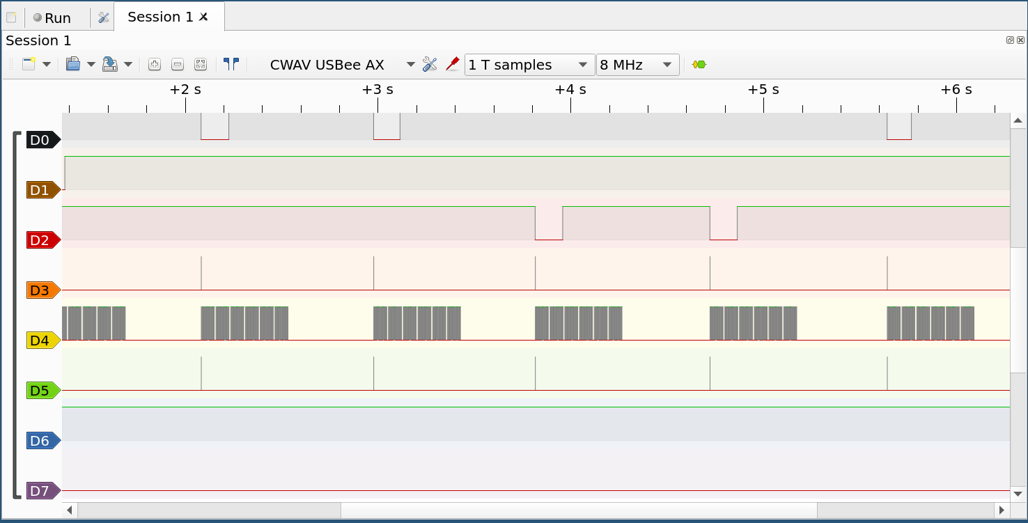
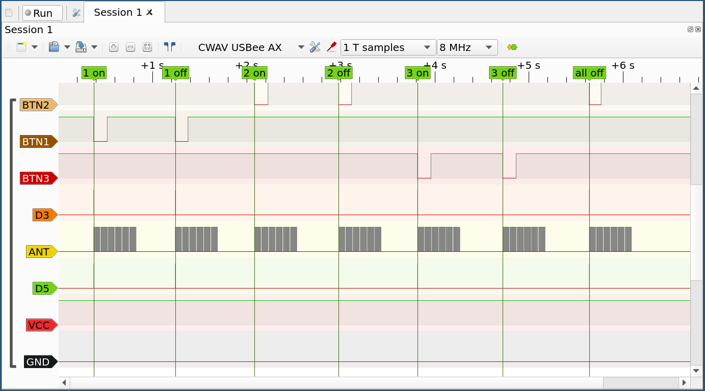
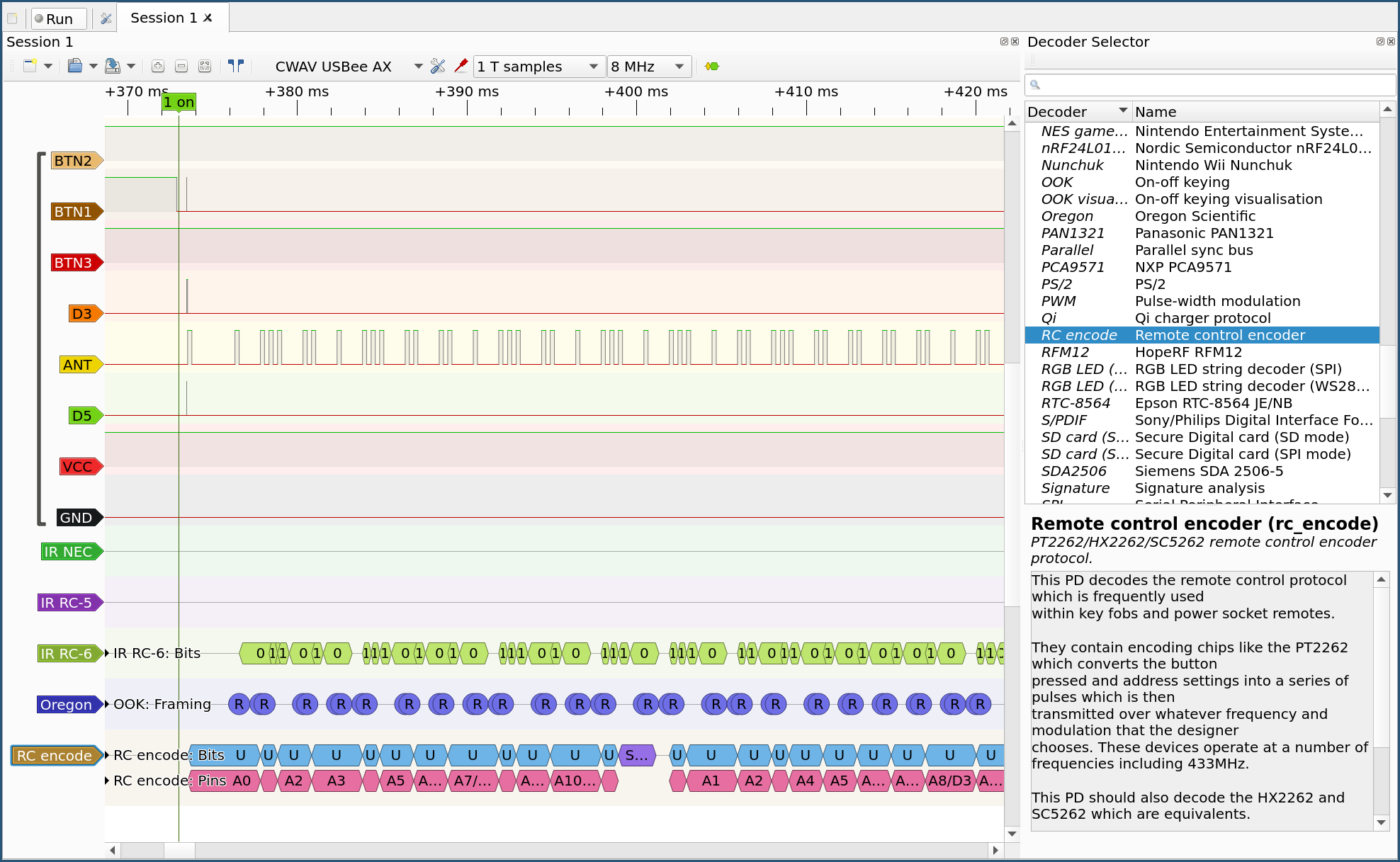
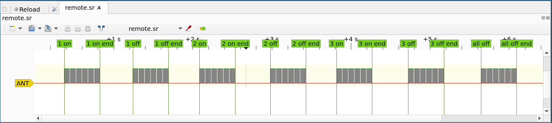
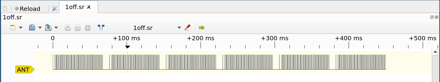
I reversed the wireless protocol. it was simple OOK.... well that was 2017 and I have to find the grc files again ;-)

Nice work.

  Are you sure? yes | no

suikale wrote 02/19/2022 at 10:20 point

Thanks! You are most likely correct. I can't confirm that at the moment because I do not have equipment for capturing the 433MHz radio signals yet

  Are you sure? yes | no

Gerben wrote 02/16/2022 at 13:05 point

Those look exactly like the ones I have. Here the are called "Klik aan Klik uit". There's already an Arduino library from controlling them ( https://github.com/vdwel/switchKaKu ). That library worked perfectly for me.

  Are you sure? yes | no

suikale wrote 02/17/2022 at 17:49 point

Thanks for the information. I posted a project log about this

  Are you sure? yes | no

Similar Projects

Does this project spark your interest?

Become a member to follow this project and never miss any updates