kelvinA
-
[T] Keyboard Shortcut Abstraction Layer
06/17/2023 at 21:39 • 4 commentsI'm mainly going to develop the workflow for #Tetent [gd0090] first, but I was also thinking about how I was going to handle keyboard shortcuts.
Similar to FreeCAD, I'm going to have the feature where you can press 2 keys (like Key Q, Key E) to do a function (in this case, switch to the Equalize constraint). The thing is, these shortcuts are chosen by where the key physically is on the keyboard. Thus, the idea I've got is to have a feature where the keyboard layout is determined or input by the user and then the software bulk-switches all the shortcuts to match up. Thus something like CTRL+Q in QWERTY would be CTRL+A in AZERTY.
-
[C] It doesn't seem that bullet/markdown CAD is going to work
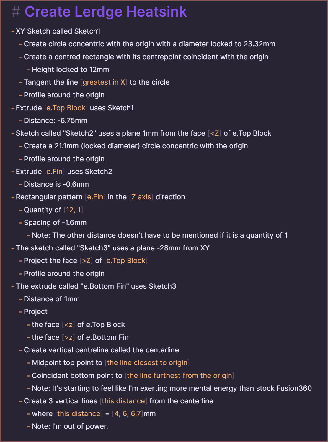
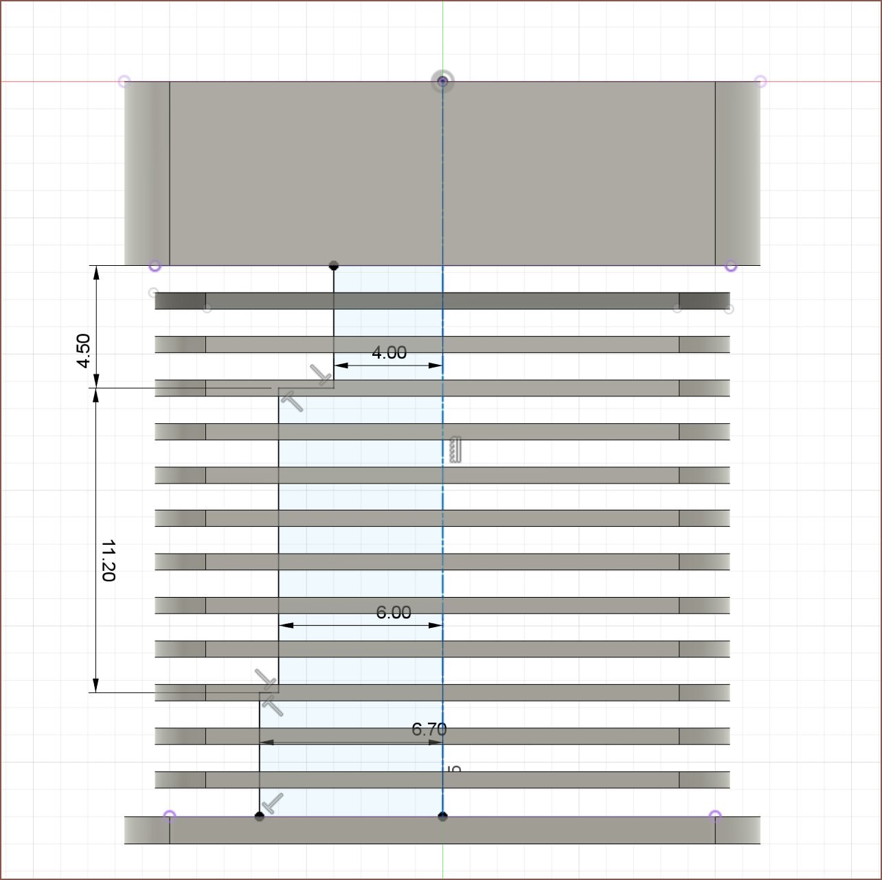
08/28/2022 at 15:08 • 1 commentToday I tried to model the Lerge heatsink for the SecSavr Sublime, and I ran out of mental power 34 mins in.
![]()
Like I noticed in the previous log, things get difficult when describing sketches. This is where I got to:
![]()
For reference, this is about halfway though the model and Me In The Past finished the entire thing in less time, even though I didn't even know how I was going to model it back then:
![]()
Thus, a solution... fails.
-
[C] Markdown Based CAD
08/28/2022 at 01:40 • 3 comments[C] = Code project log
With the requirement of research for #SecSavr Suspense [gd0105] dwindling down, I'm starting to suspect that all my projects seem to slow down or stall because of Fusion360. I'm wondering if it's just modelling in CAD in general, but I don't like the idea of spending 10s of hours in Fusion for what I think should take 1/10th the time. Even if I get to the other side with a completed model, projects like #Revolving Hotend [gd0012] just take a hard stall straight after and this seemingly random phenomenon could actually be attributed to all my mental energy being spent on Fusion360!
My research concludes that creating a new CAD package is a long and multi-year process, and I don't really have that kind of time, so I'm hoping to meet in the middle somewhere and feed my custom stuff with all the instructions into a Fusion360 plugin, kind of like Grasshopper or CAD Sketcher.
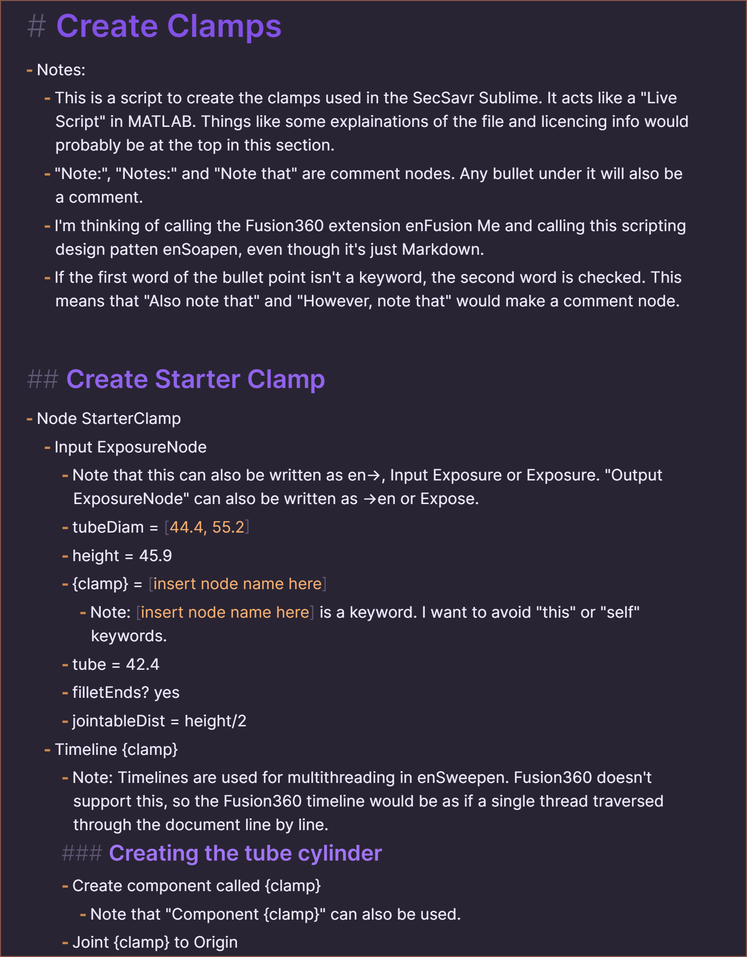
Suprisingly, searching "markdown based CAD" on the internet produces no relevant results. I was under the impression that, similar to many things being written in JavaScript, if a task is doable in text it's been done in Markdown. So I opened Obsidian and got to writing some clamps I modelled for gd0036. Here's the raw:
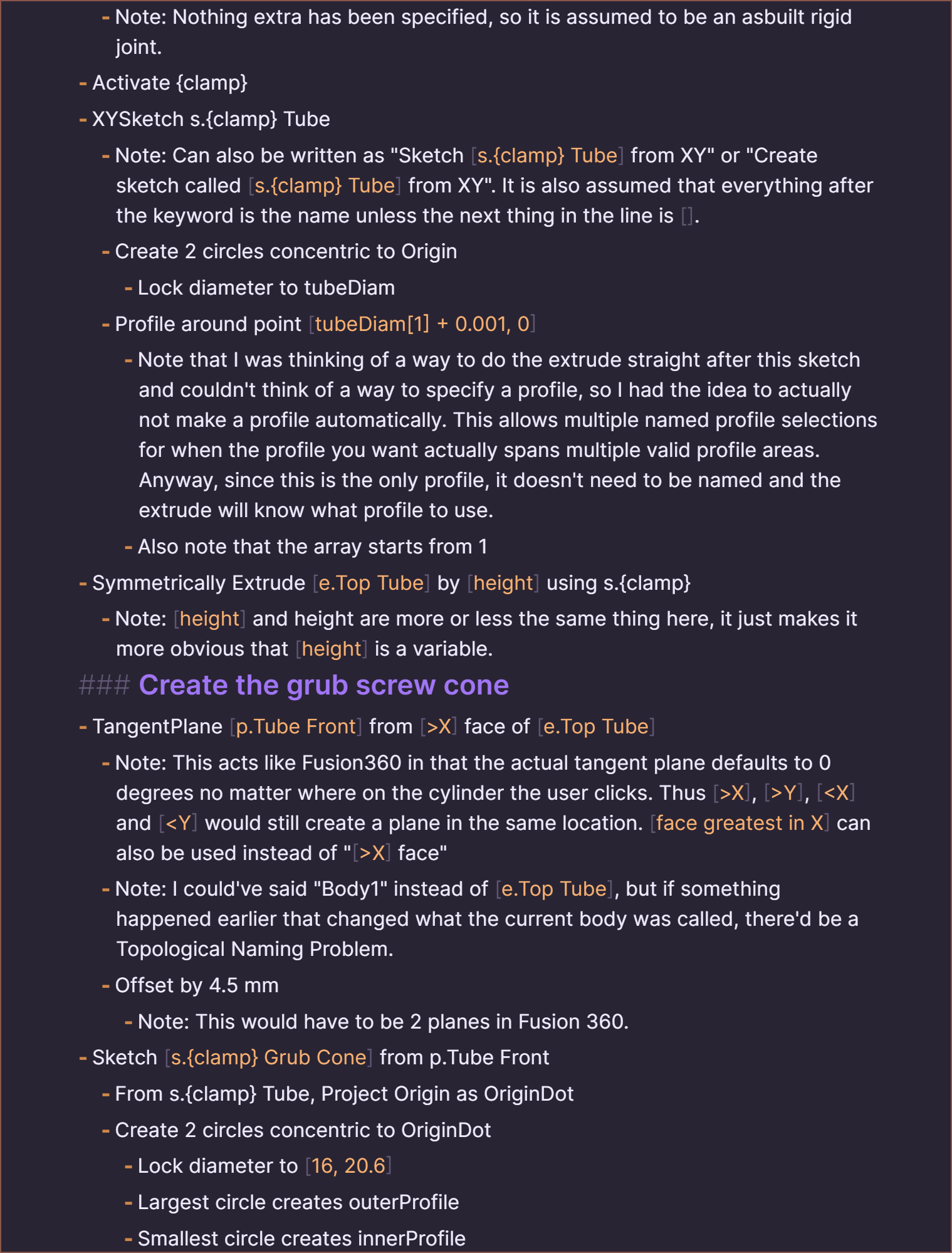
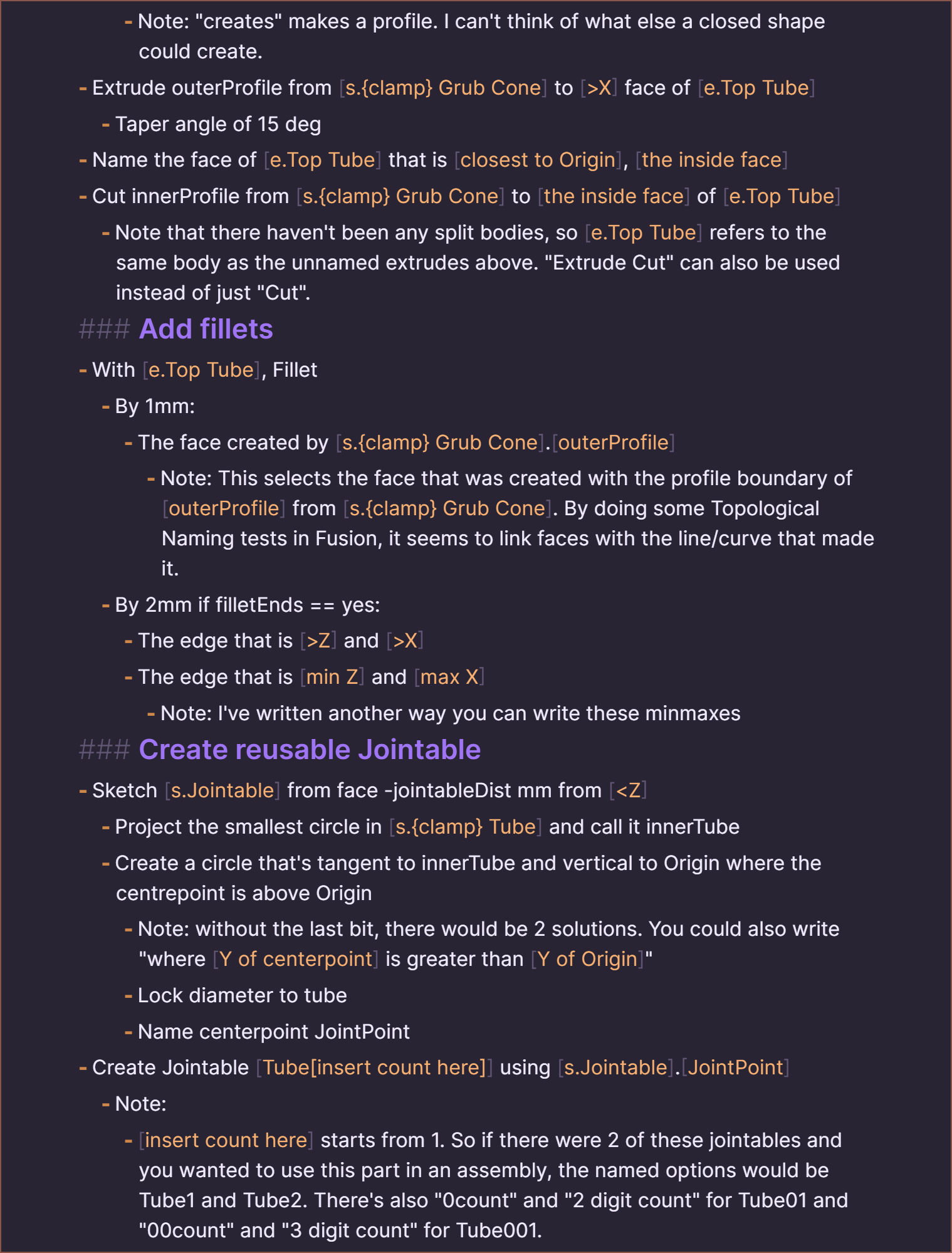
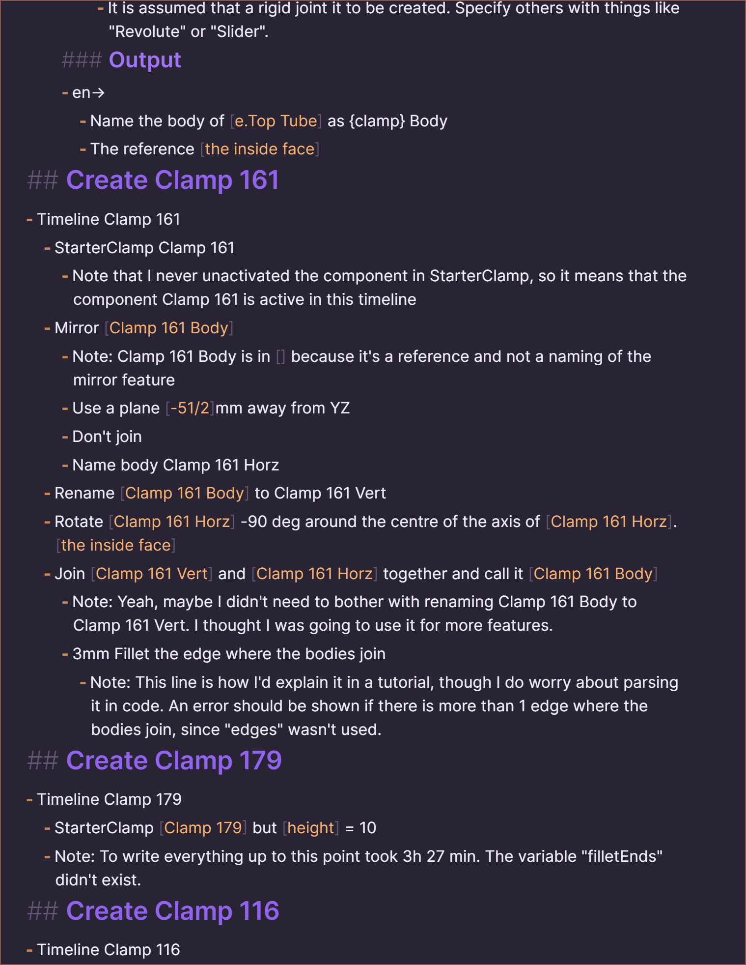
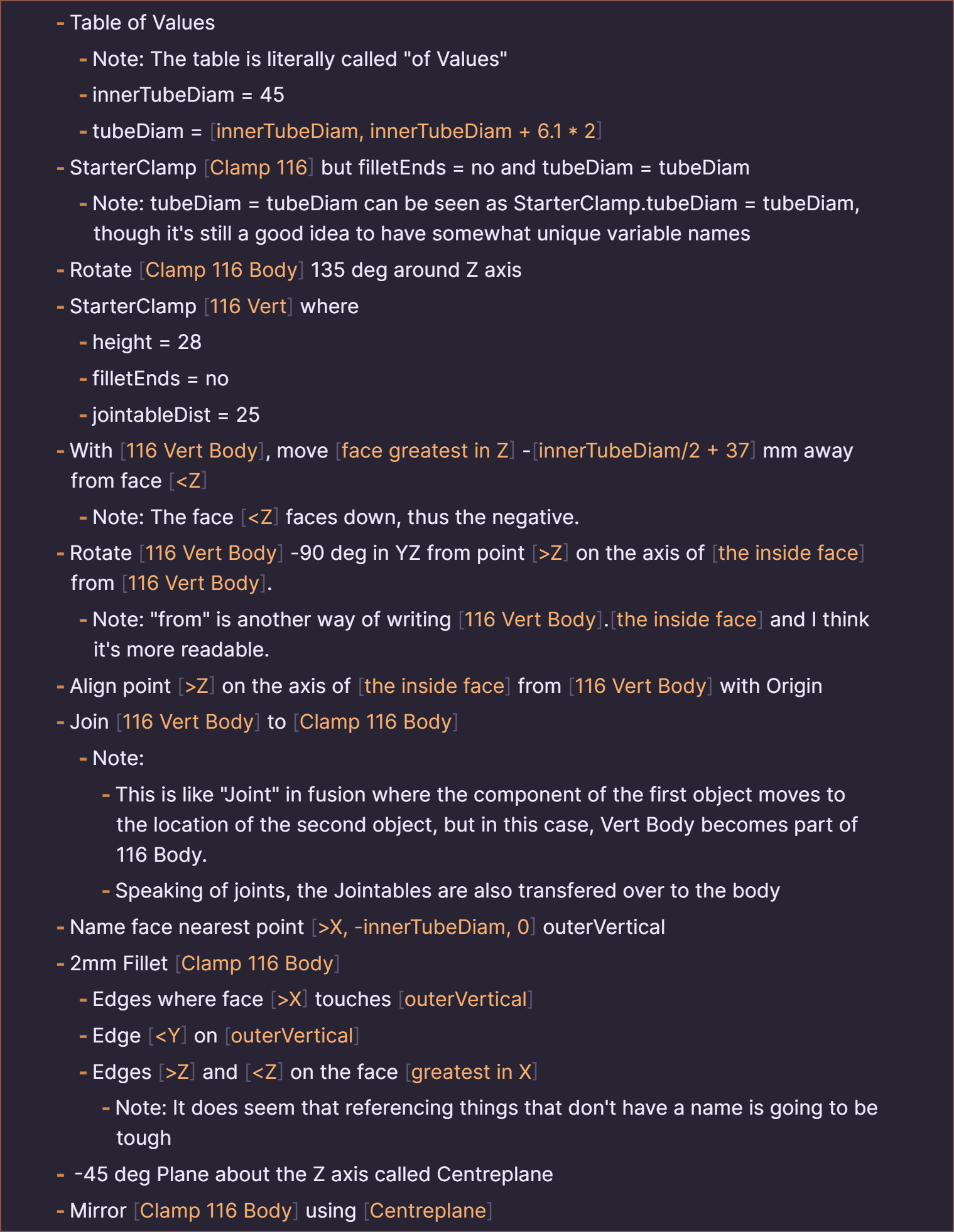
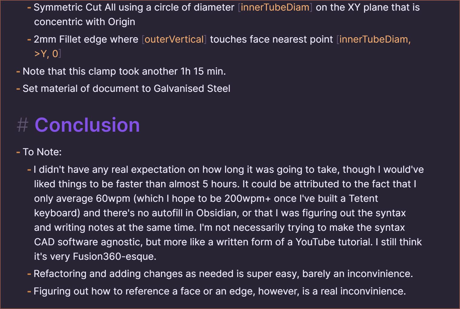
# Create Clamps
- Notes:
    - This is a script to create the clamps used in the SecSavr Sublime. It acts like a "Live Script" in MATLAB. Things like some explainations of the file and licencing info would probably be at the top in this section.
    - "Note:", "Notes:" and "Note that" are comment nodes. Any bullet under it will also be a comment.
    - I'm thinking of calling the Fusion360 extension enFusion Me and calling this scripting design patten enSoapen, even though it's just Markdown.
    - If the first word of the bullet point isn't a keyword, the second word is checked. This means that "Also note that" and "However, note that" would make a comment node.


## Create Starter Clamp
- Node StarterClamp
    - Input ExposureNode
        - Note that this can also be written as en->, Input Exposure or Exposure. "Output ExposureNode" can also be written as ->en or Expose.
        - tubeDiam = [44.4, 55.2]
        - height = 45.9
        - {clamp} = [insert node name here]
            - Note: [insert node name here] is a keyword. I want to avoid "this" or "self" keywords.
        - tube = 42.4
        - filletEnds? yes
        - jointableDist = height/2
    - Timeline {clamp}
        - Note: Timelines are used for multithreading in enSweepen. Fusion360 doesn't support this, so the Fusion360 timeline would be as if a single thread traversed through the document line by line.
        ### Creating the tube cylinder
        - Create component called {clamp}
            - Note that "Component {clamp}" can also be used.
        - Joint {clamp} to Origin
            - Note: Nothing extra has been specified, so it is assumed to be an asbuilt rigid joint.
        - Activate {clamp}
        - XYSketch s.{clamp} Tube
            - Note: Can also be written as "Sketch [s.{clamp} Tube] from XY" or "Create sketch called [s.{clamp} Tube] from XY". It is also assumed that everything after the keyword is the name unless the next thing in the line is [].
            - Create 2 circles concentric to Origin
                - Lock diameter to tubeDiam
            - Profile around point [tubeDiam[1] + 0.001, 0]
                - Note that I was thinking of a way to do the extrude straight after this sketch and couldn't think of a way to specify a profile, so I had the idea to actually not make a profile automatically. This allows multiple named profile selections for when the profile you want actually spans multiple valid profile areas. Anyway, since this is the only profile, it doesn't need to be named and the extrude will know what profile to use.
                - Also note that the array starts from 1
        - Symmetrically Extrude [e.Top Tube] by [height] using s.{clamp}
            - Note: [height] and height are more or less the same thing here, it just makes it more obvious that [height] is a variable.
        ### Create the grub screw cone
        - TangentPlane [p.Tube Front] from [>X] face of [e.Top Tube]
            - Note: This acts like Fusion360 in that the actual tangent plane defaults to 0 degrees no matter where on the cylinder the user clicks. Thus [>X], [>Y], [X] face"
            - Note: I could've said "Body1" instead of [e.Top Tube], but if something happened earlier that changed what the current body was called, there'd be a Topological Naming Problem.
            - Offset by 4.5 mm
                - Note: This would have to be 2 planes in Fusion 360.
        - Sketch [s.{clamp} Grub Cone] from p.Tube Front
            - From s.{clamp} Tube, Project Origin as OriginDot
            - Create 2 circles concentric to OriginDot
                - Lock diameter to [16, 20.6]
                - Largest circle creates outerProfile
                - Smallest circle creates innerProfile
                - Note: "creates" makes a profile. I can't think of what else a closed shape could create.
        - Extrude outerProfile from [s.{clamp} Grub Cone] to [>X] face of [e.Top Tube]
            - Taper angle of 15 deg
        - Name the face of [e.Top Tube] that is [closest to Origin], [the inside face]
        - Cut innerProfile from [s.{clamp} Grub Cone] to [the inside face] of [e.Top Tube]
            - Note that there haven't been any split bodies, so [e.Top Tube] refers to the same body as the unnamed extrudes above. "Extrude Cut" can also be used instead of just "Cut".
        ### Add fillets
        - With [e.Top Tube], Fillet
            - By 1mm:
                - The face created by [s.{clamp} Grub Cone].[outerProfile]
                    - Note: This selects the face that was created with the profile boundary of [outerProfile] from [s.{clamp} Grub Cone]. By doing some Topological Naming tests in Fusion, it seems to link faces with the line/curve that made it.
            - By 2mm if filletEnds == yes:
                - The edge that is [>Z] and [>X]
                - The edge that is [min Z] and [max X]
                    - Note: I've written another way you can write these minmaxes
        ### Create reusable Jointable
        - Sketch [s.Jointable] from face -jointableDist mm from [
            - Name the body of [e.Top Tube] as {clamp} Body
            - The reference [the inside face]
## Create Clamp 161
- Timeline Clamp 161
    - StarterClamp Clamp 161
        - Note that I never unactivated the component in StarterClamp, so it means that the component Clamp 161 is active in this timeline
    - Mirror [Clamp 161 Body]
        - Note: Clamp 161 Body is in [] because it's a reference and not a naming of the mirror feature
        - Use a plane [-51/2]mm away from YZ
        - Don't join
        - Name body Clamp 161 Horz
    - Rename [Clamp 161 Body] to Clamp 161 Vert
    - Rotate [Clamp 161 Horz] -90 deg around the centre of the axis of [Clamp 161 Horz].[the inside face]
    - Join [Clamp 161 Vert] and [Clamp 161 Horz] together and call it [Clamp 161 Body]
        - Note: Yeah, maybe I didn't need to bother with renaming Clamp 161 Body to Clamp 161 Vert. I thought I was going to use it for more features.
        - 3mm Fillet the edge where the bodies join
            - Note: This line is how I'd explain it in a tutorial, though I do worry about parsing it in code. An error should be shown if there is more than 1 edge where the bodies join, since "edges" wasn't used.
## Create Clamp 179
- Timeline Clamp 179
    - StarterClamp [Clamp 179] but [height] = 10
    - Note: To write everything up to this point took 3h 27 min. The variable "filletEnds" didn't exist.
## Create Clamp 116
- Timeline Clamp 116
    - Table of Values
        - Note: The table is literally called "of Values"
        - innerTubeDiam = 45
        - tubeDiam = [innerTubeDiam, innerTubeDiam + 6.1 * 2]
    - StarterClamp [Clamp 116] but filletEnds = no and tubeDiam = tubeDiam
        - Note: tubeDiam = tubeDiam can be seen as StarterClamp.tubeDiam = tubeDiam, though it's still a good idea to have somewhat unique variable names
    - Rotate [Clamp 116 Body] 135 deg around Z axis
    - StarterClamp [116 Vert] where
        - height = 28
        - filletEnds = no
        - jointableDist = 25
    - With [116 Vert Body], move [face greatest in Z] -[innerTubeDiam/2 + 37] mm away from face [Z] on the axis of [the inside face] from [116 Vert Body].
        - Note: "from" is another way of writing [116 Vert Body].[the inside face] and I think it's more readable.
    - Align point [>Z] on the axis of [the inside face] from [116 Vert Body] with Origin
    - Join [116 Vert Body] to [Clamp 116 Body]
        - Note:
            - This is like "Joint" in fusion where the component of the first object moves to the location of the second object, but in this case, Vert Body becomes part of 116 Body.
            - Speaking of joints, the Jointables are also transfered over to the body
    - Name face nearest point [>X, -innerTubeDiam, 0] outerVertical
    - 2mm Fillet [Clamp 116 Body]
        - Edges where face [>X] touches [outerVertical]
        - Edge [Z] and [Y, 0]
- Note that this clamp took another 1h 15 min.
- Set material of document to Galvanised Steel

# Conclusion
- To Note:
    - I didn't have any real expectation on how long it was going to take, though I would've liked things to be faster than almost 5 hours. It could be attributed to the fact that I only average 60wpm (which I hope to be 200wpm+ once I've built a Tetent keyboard) and there's no autofill in Obsidian, or that I was figuring out the syntax and writing notes at the same time. I'm not necessarily trying to make the syntax CAD software agnostic, but more like a written form of a YouTube tutorial. I still think it's very Fusion360-esque.
    - Refactoring and adding changes as needed is super easy, barely an inconvinience.
    - Figuring out how to reference a face or an edge, however, is a real inconvinience.
Here's what I see in Obsidian:
![]()
![]()
![]()
![]()
![]()
![]()
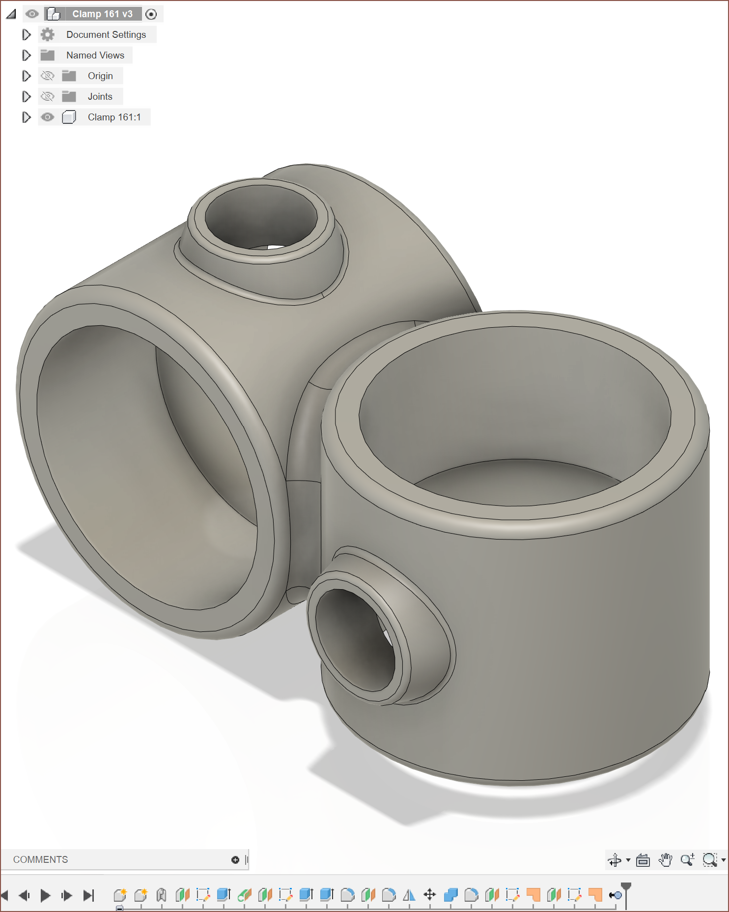
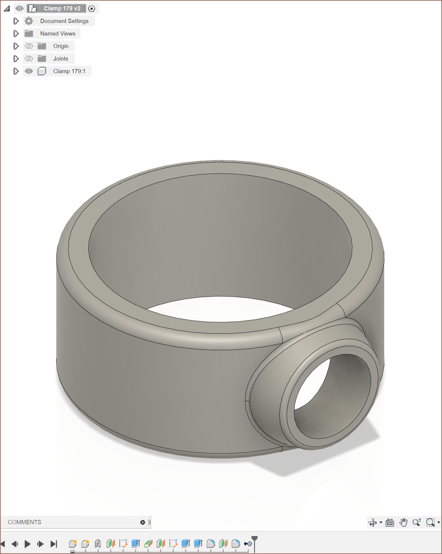
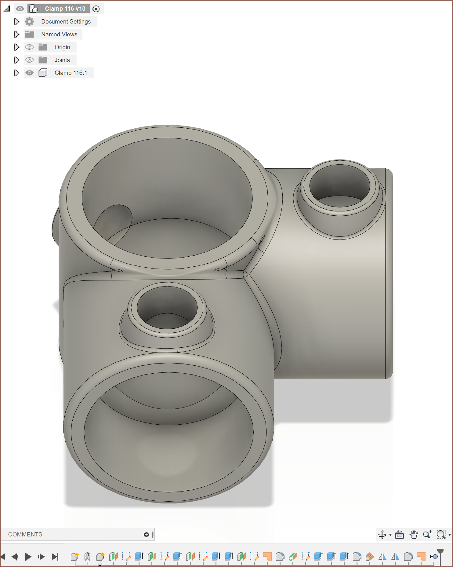
And here is the intended results (minus the Fusion360 group stuff like the temp component created at the start and deleted at the end):
![]()
![]()
![]()
It's 2:38am right now, so I'm too tired to make sure the syntax is completely consistent, but this should give anyone reading an idea as to what I'm envisioning.
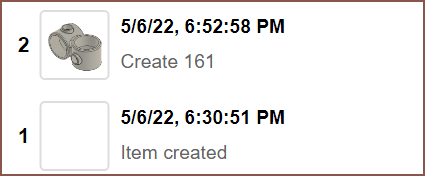
For reference of time:
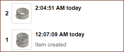
![]()
Clamp 161: 22 minutes
![]()
Clamp 179: I think about 2 mins
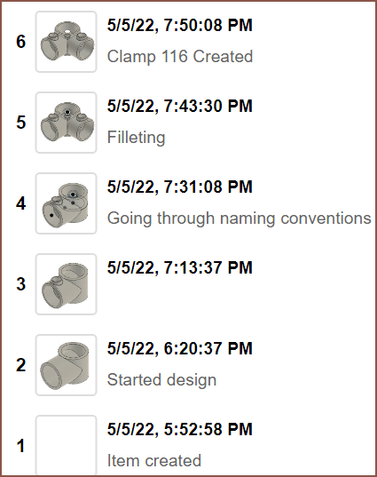
![]()
Clamp 116: About 1h 45 min
-
[T] Bullet-based CAD
08/16/2022 at 07:59 • 1 commentI just got an idea. I've been thinking about Fornjot-developer's stance on code-based CAD and I saw the appeal in everything (like git versioning and vast text editor options) except the code. Now I'm thinking that I just need to think differently on how the "code" is layed out. With bullet points, I can visualise a solution that works like the node-based solution, just in raw text. It's like the merge of HTML, the "with" keyword from Visual Basic, indentation from Python, CLI syntax and a dash of cadquery.
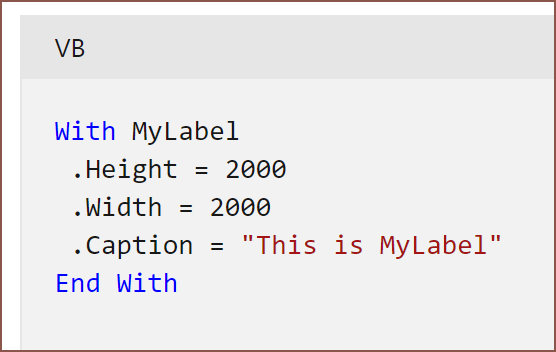
For those unaware, if I recall correctly, the with keyword in VBA went something like this:
with Application.Current()
    .action1
    .action2
end with
Searches it up...
![]()
Yeah something like that.
The reason I prefer this idea to something like codeblocks (think Scratch) is that the path of operations is linear by scrolling down, and features aren't encapsulated inside other features. I'd very much like to be able to use 1 sketch for more than 1 extrude.
CadQuery is pretty cool in that it captures more design intent. The main showcase is with .faces(">Z"), which finds and selects the face of the parent object with the highest Z elevation.
Proposed Example
- Exposurenode in - CarriageLength = 40 # Exposurenodes are all the things you want to expose to other # files. "Exposurenode in" works like function arguments for # the group (each feature bullet is a group, like Timeline or # Sketch) and "Exposurenode" is the output. The vast majority # of Exposurenodes don't need to be visible or specified by the # user. - Timeline MainTimeline
- Joint Carriage to Rail - Slider along XZ # Specify if joint type is different from # file defaults - Jointpoint1 - Select centre snap position from <Z face - Jointpoint2 - Select centre snap position from >Z face - Timeline CreateRail # This bullet is actually minimised # Each Timeline is computed from the start at the same time. This # is why the MainTimeline can reference from Timeline's under it. # Unless you make a sub-timeline, features under a timeline are # procedural. You can think of Timeline's more like media tracks # in video editing software. Want max multithreading? You gotta # bump those Timeline's up. - Timeline CreateCarriage - Sketch from XZ Plane - Centerpoint Rectangle from Origin # In Fusion, the above would be clicking "Center Rectangle" # and clicking from the origin. Using "coincident to" # instead of "from" would apply a constraint to the centre # of the rectangle. - Width: 20mm Locked # Locked = Dimension to this value - Height: 10mm Locked - Nonplanar # All sketch entities that you don't # want auto planar constraints - Line - Set as Guide Rail # This is for the sweep - Coincident Line01 Startpoint to Origin - Perpendicular Line01 to XZ plane - Dimension Line01 to CarriageLength mm - Sweep Sketch01 - Make Body01 into Component called Carriage -
[R] Smartwatch Screens
06/22/2022 at 11:17 • 0 commentsSo I decided to scan the Android smartwatch market to see if I can replace my aging Zeblaze Thor Pro and I thought that it would also be a good time to see what kind of variance there is in smartwatch screens these days.
UI Sketch
For starters, it seems I forgot to write a log about the UI design I started on the train from the Birmingham, UK TCT show.
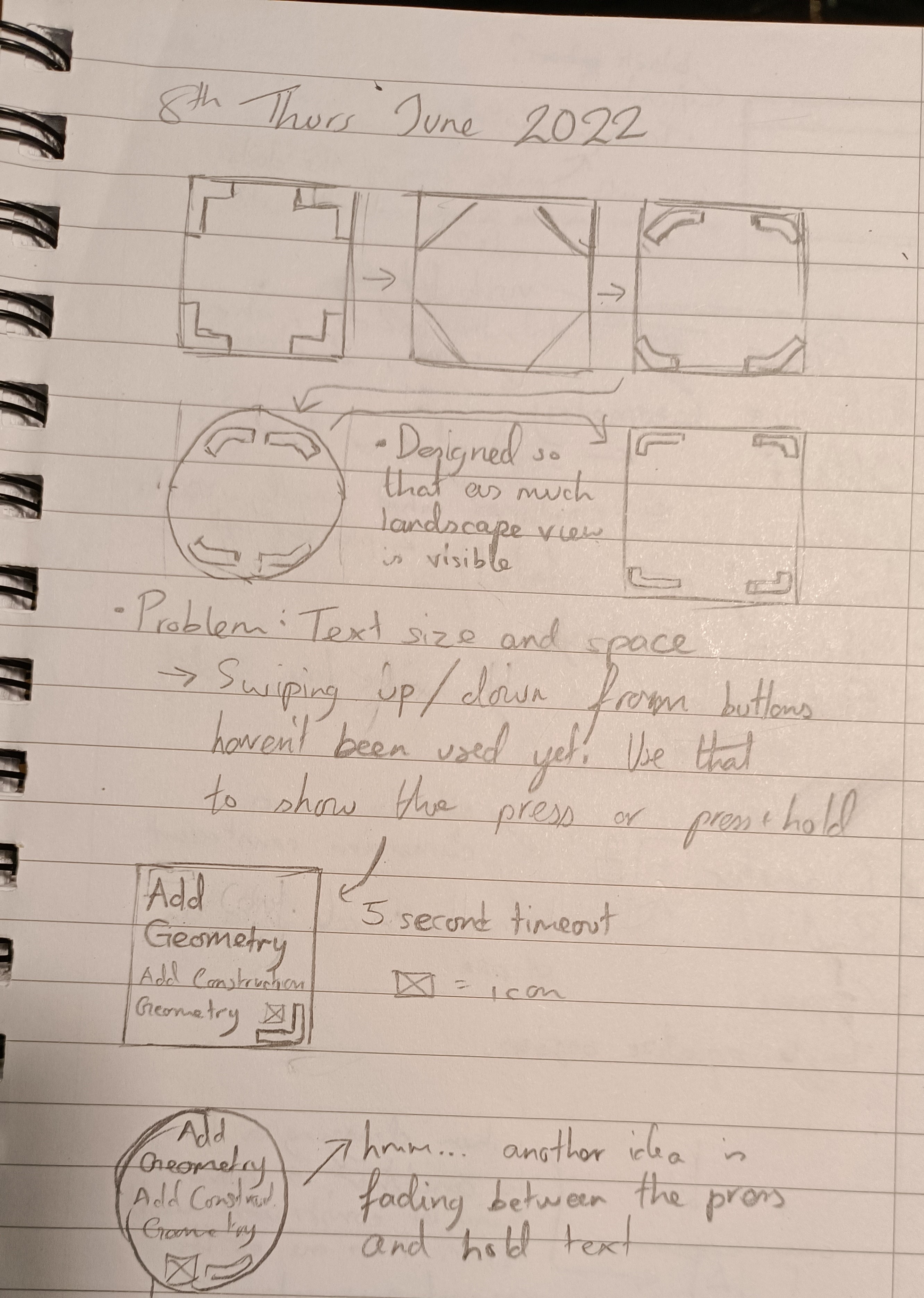
![]()
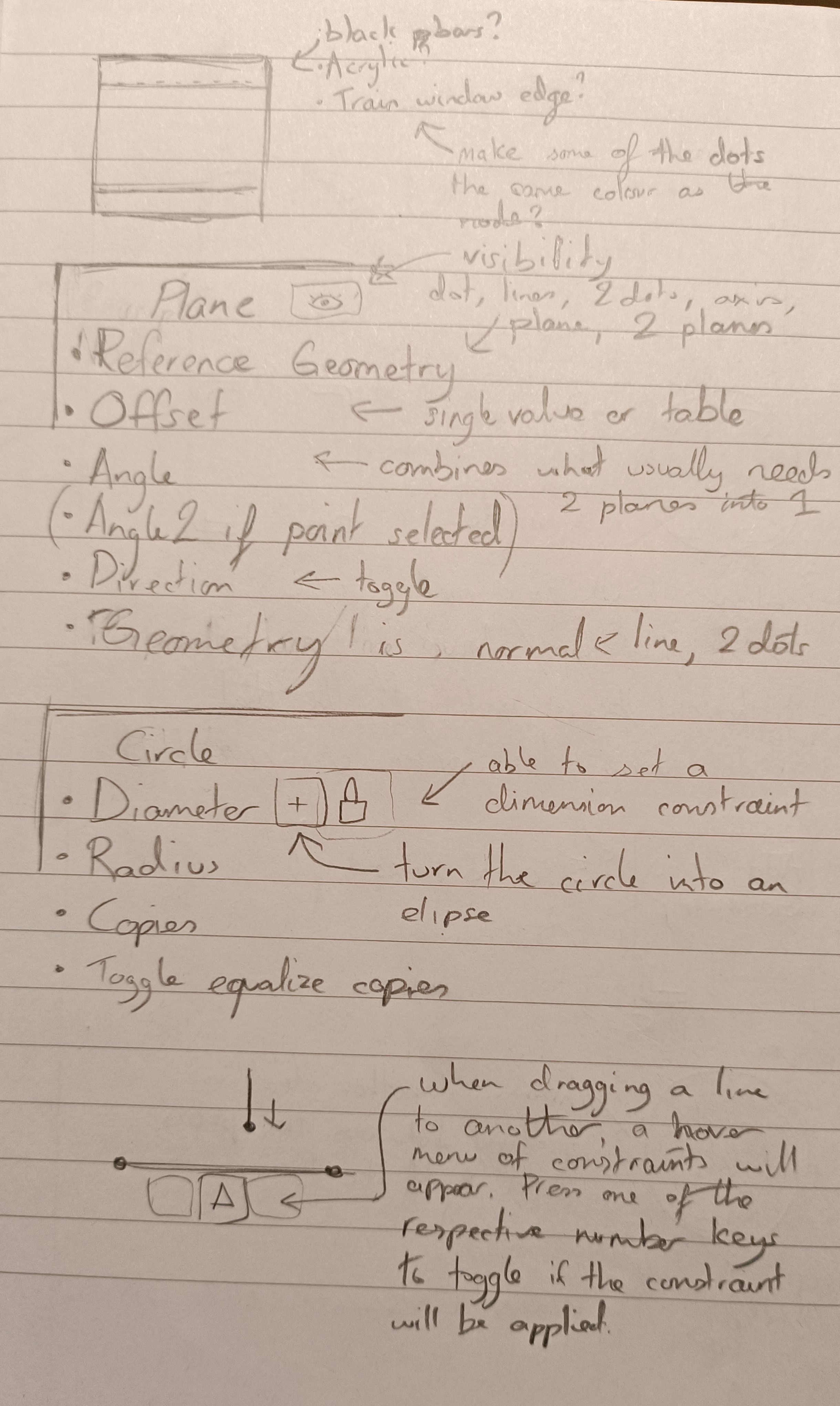
So the arrows show things like design progression. I'm thinking of a thick line that has a smooth bend when hitting the corners. As seen in this log, there would be a press and a press+hold function of the buttons. Then I thought about how a new user would think when they just started the app for the first time and added a swipe gesture to open a tooltip with a 5 second timeout.
![]()
Then I started thinking about the look of the area behind the buttons. Should it be acrylic like Windows 10/11, black bars or maybe even something like the edge of the windows in the train I was in:
 After that, I started thinking about some example nodes so that I could create a UI for it. There would be a lock button next to entries like "Diameter" which will set a dimension constraint without having to add seperate nodes.
I also thought of a desktop UI feature where the user could toggle what constraints to apply whilst something like a line was being dragged. For example, you want to keep the vertical constraint of the line you're currently dragging, but aren't aligned with the midpoint of the horizontal line below. The user should be able to press 2 on the keyboard to say to the software "I want to keep the vertical constraint, but also apply a midpoint constraint to the endpoint I'm currently dragging.".
---------- more ----------Circular
The Thor has a 1.6 inch transflective display and is the only smartwatch I've ever had that preserves the time when reaching 0% battery. Due to that, and the fact that I was never all that keen on the round screen, I basically glossed over all of todays options on the market. It does seem that there are more 1.6 inch screen watches now compared to back when I got the Thor and 1.6 was the exception.
It looks like the common sizes are 1.39" for the smaller and/or older watches and 1.6" for the more flagship grade watches, and other than resolution they're pretty much all the same as far as the UI for enSweepen is concerned.
The only outlier is still the LEM X with its 2.03" screen and bottom chin. I do wish LEMFO came out with a new version that was a full circle.
![Black Lemfo LEM X 4G Smart Watch, Rs 17900 Zeblaze Solutions LLP | ID: 20811816230]()
Square/Rectangular
Now the square and rectangular watches have more variance. As far back as when Android was put in a smartwatch, and even before, there were watch phones like this:
![The World's First SmartWatch That's Actually A Smartphone! Move Over iWatch! -- 3G Watches | PRLog]() alongside square ones like this:
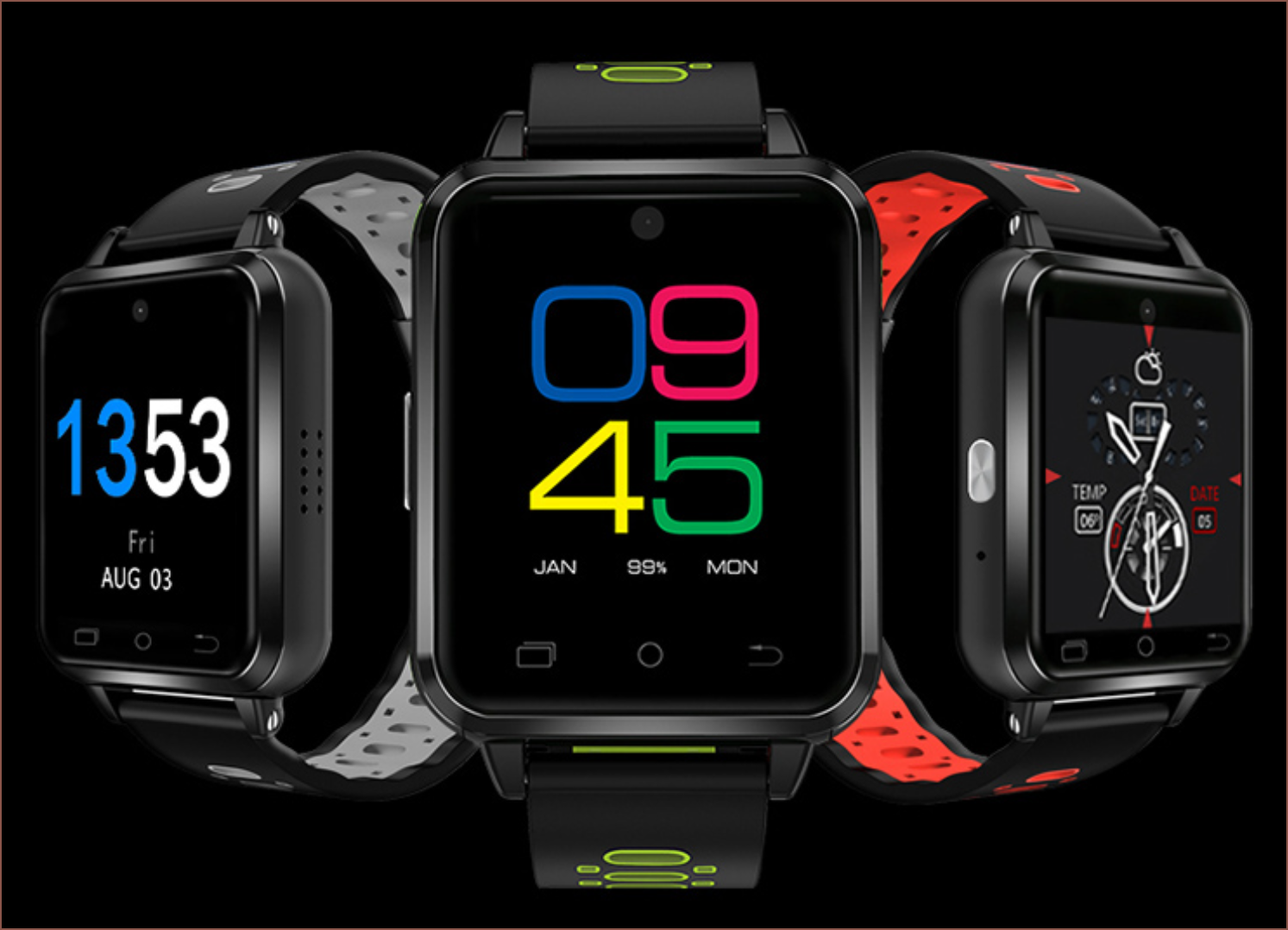
alongside square ones like this:![ZGPAX S5 Watch Smart Phone Dual Core 1.54 Inch Capacitive Touch Screen Android 4.0 512MB RAM+4G ROM 2MP Camera with GPS - Silver+Black]() It still looks like most of the square watches today are 1.54" and either 240 or 320px, and that the large, rectangle ones have a 4:3 aspect ratio. Strangely enough, 3 out of the 4 large watches I've had broke at the strap (e.g. LEM T, DM98) and I hypothesise that the 4th one broke due to water getting in through a crack near the strap (Ticwris MAX), so it's probably for the best if I pass on the DM101:
It still looks like most of the square watches today are 1.54" and either 240 or 320px, and that the large, rectangle ones have a 4:3 aspect ratio. Strangely enough, 3 out of the 4 large watches I've had broke at the strap (e.g. LEM T, DM98) and I hypothesise that the 4th one broke due to water getting in through a crack near the strap (Ticwris MAX), so it's probably for the best if I pass on the DM101:![]() Searching some more, I found this very nice looking watch with an AMOLED screen:
Searching some more, I found this very nice looking watch with an AMOLED screen:![]()
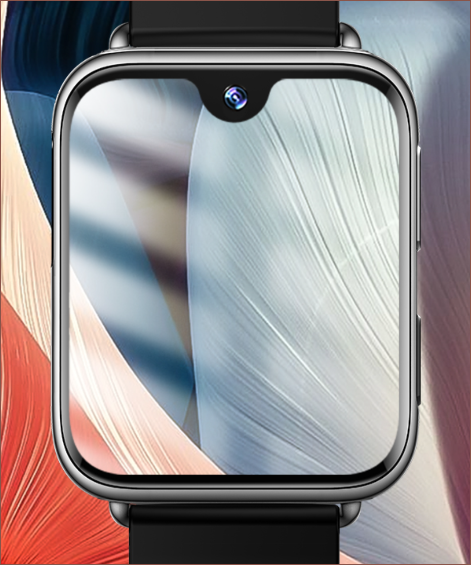
The i3 AMOLED watch. I was able to find some videos (Video1, Video2, Video3) despite it having such a generic name. The thing is, it's got a notch and curved edges:![]()
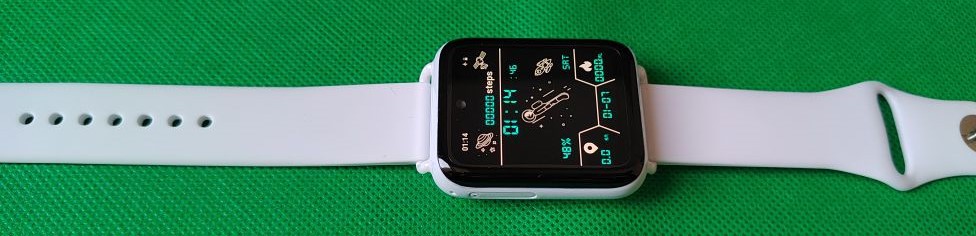
Basically a screen "never before seen in this industry". The cool thing about the notch is that the status bar is always visible, like a smartphone, unlike other smartwatches I've had in the past. Now in usual app development fashion, targetting such a specific screen design that would probably only be used by an incredibly small potential user base would be somewhat pointless. However, since I'm most likely going to pick up this watch on the Monday 27th sale, le obviously I've got to.![]() I think it would look nice with the #Teti [gd0022], #TetInventory [gd0039] and #TEOSS [gd0037] all-white look I'm aiming for, and the screen is probably the single most important feature of a smartwatch. I've had the Finow Q1 Pro and while it was amazing on paper (one of the first 4G smartwatches, removable strap, capacitive buttons), it's 30fps (possibly lower), 240p screen completely ruined it.
I think it would look nice with the #Teti [gd0022], #TetInventory [gd0039] and #TEOSS [gd0037] all-white look I'm aiming for, and the screen is probably the single most important feature of a smartwatch. I've had the Finow Q1 Pro and while it was amazing on paper (one of the first 4G smartwatches, removable strap, capacitive buttons), it's 30fps (possibly lower), 240p screen completely ruined it.![]()
The Finow Q1 Pro. Great specs. Mutliple colours. Nice fit. Trash screen. Virtually every other Android smartwatch only has a power button and most have a back button, requiring the use of some 3rd party app or gestures to get the missing ones back, so having capacitive ones in the area that would have otherwise been a plain black bezel was a very welcome feature. -
[A] Project renamed to enSweepen
06/18/2022 at 11:38 • 0 comments[A] = Announcement
I've decided to go though with the name change.
-
[T] Fusion 360 Used Modelling Features
06/16/2022 at 17:59 • 0 commentsI've compiled a list of features, in order of importance, required in another program to be able to port over my Fusion 360 designs. Some features have been grouped together and there are some additional features I wish Fusion had sprinked about. The grouped together features aren't in any particular order.
- Parameters / functions
- Components
- Sketches
- Constraints
- Coincident
- Equal
- Midpoint
- Horz/vert
- Tangent
- Symmetry
- Planar
- Colinear
- Parallel
- Perpendicular
- Lock
- Dimension Tool
- Profiles
- Project / include
- Redefine sketch plane
- Offset
- Text
- Extend / trim
- Polygon
- Helix
- Constraints
- 3D / 2D Patterns
- Circular
- Rectangular
- On path
- Joints
- Rigid
- As-built
- Slider
- Revolve
- Rigid body
- Extrude To
- Revolve
- Loft
- Sweep
- Chamfer / fillet
- Variable
- Different angle
- Different lengths
- Mirror
- Combination
- Defeature
- Align
- Patch / thicken
- Scale
- Shell
- Version history
- Name features
- Groups
- Timeline
- Split body/face
- Measure distances
- Planes
- Midplane
- Tangent
- Appearance
- Selecting through faces
- Section view
- Procedural move/rotate faces
- Draft
- Push-pull
- Threads
- Modelled / textured
- Sheet Metal
- Emboss/cut onto curve
- Import/export
- .step
- .dxf
- .svg
- Image canvas
- 3MF/STL
Whilst the list of features is long, it does make the problem feel a measurable amount more feasible to achieve.
Looking at the development of Fornjot (video below), it seems that the timescale would be quite long to get to a desirable stage, thus I should continue modelling in Fusion 360 while I slowly work on this project on the side. I still think gd0096 would still be useful as a tool to plan designs before modelling it in CAD if it wasn't connected to a geometric kernel.
-
[T] Kernel Choice: Fornjot over OCCT?
06/10/2022 at 18:47 • 0 commentsMaybe OCCT's gotten better in the past few months/years, but I've heard that FreeCAD's been kind of rocky with bugs because of it. It's also decades old, which is a double edged sword from my point of view; while feature rich, it may be difficult to add new features, understand old ones or implement Quality Of Life (QOL) enhancements, as seen in FreeCAD. I've also heard that OCCT also takes a considerable amount of time to learn.
Fornjot is the new kernel on the block, has similar goals to this project and seems to get a considerable amount of progress done each week. It could also help both projects progress, as explained in this blog post.
I've still got a lot of work to do before I even need to start interfacing with a geometric kernel, so there is the option of delaying the decision until I get to that point.
-
[T] Name Idea: enSweepen
06/10/2022 at 18:33 • 0 commentsReasons why I thought of this:
- Sounds smoother to say than "sketch", especially the phrase "enSweepen me!" over "enSketchen me!".
- Seems more consistent of a name than "loft" when looking at it with the rest of the SecSavr ecosystem.
- Sweep is one of the main 4 body creation tools, and one that usually requires more than one sketch in other CAD programs, showcasing the multi-plane sketch workflow of this project.
- Timeline / file cleanliness and housekeeping is a priority.
- Sounds refined because it is similar in sound to "ensuite".
- Timelines could possibly look like a 2D sweep operation, maybe?
-
[T] Branding
05/30/2022 at 08:12 • 0 commentsSome branding ideas to further explore the idea of "enLoften" over "enSketchen".
![]()
![]()
enSweepen [gd0096]
Procedural and parametric, node-based CAD for 3D modelling with sketches.


 alongside square ones like this:
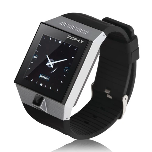 It still looks like most of the square watches today are 1.54" and either 240 or 320px, and that the large, rectangle ones have a 4:3 aspect ratio. Strangely enough, 3 out of the 4 large watches I've had broke at the strap (e.g. LEM T, DM98) and I hypothesise that the 4th one broke due to water getting in through a crack near the strap (Ticwris MAX), so it's probably for the best if I pass on the DM101:
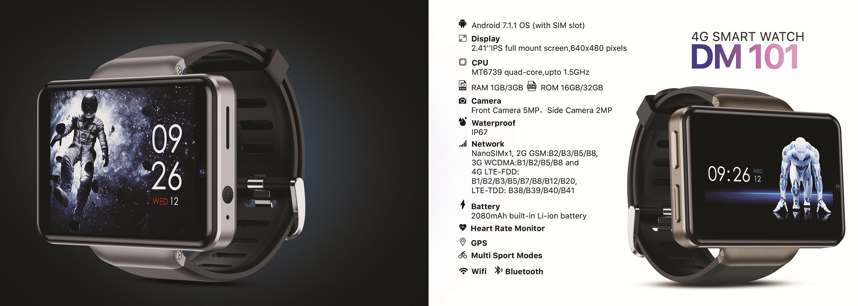 Searching some more, I found
 I think it would look nice with the