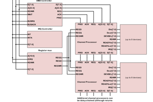
This project aims to do most things using lookup tables (LUTs) that are in ROMs that are copied into fast SRAMs on boot. It intends to have a 3-stage or 4-stage pipeline. The stages are:
1. Fetch -- Loads the instructions from the SRAM that is shadowing the system ROM into the Instruction Register.
2. Decode -- Uses the address lines to look up the opcodes and convert them to control signals on the control SRAM's data lines. The instruction decoder is a ROM to make it easier to replace unused or redundant instructions. New native instructions can be added this way. It is possible to merge fetch and decode by feeding the instruction ROM through the control matrix ROM on boot and storing that into SRAMs.
3. Access -- Memory accesses are to occur before the ALU stage since only reads are processed. Writes always come directly from registers. A high-speed SRAM is used to hold user data. So the reads are done in this stage and placed into the pipeline registers to either be worked on by the ALU or forwarded to the accumulator in the next stage.
4. ALU -- This will use a ROM that is shadowed into a fast SRAM that uses 20-21 address bits. Sixteen of the address bits will be used as the two 8-bit operands. The other bits will be used for control lines to set the operation. The ROM and SRAM pair likely should be 16-bits wide to allow for a flags register. While the memory could have 19 address lines, more would enable adding additional instructions.
Additional Instructions
Possible additional instructions besides new memory modes and registers could include:
1. Full left and right shifter -- The Gigatron has the Ac=Ac+Ac instruction. That could be expanded to use the operand field that is currently unused. An operand of 0 could still function as Ac=Ac+Ac. In fact, the same instruction could be used for a right shifter by using another bit. You'd only need 5 bits to do both, and the highest bit of those would be the direction bit. While it takes 3 bits to represent 8 possibilities, it would be nice to start with 1 to avoid confusion and let a 0 function as 1 for current compatibility. So that leaves a value of 7. So if you want to shift 8 places (all zeroes, but you could then copy to/from another register (such as a fixed point register or an upper register to help with 16-bit vCPU ops), then being able to shift by 8 would be helpful, then another bit would be used. And this could leave room to allow for 16-bit operations, though only up to 15 bits. The other 224 pages of the ALU shifter segment could possibly be used for other things such as an RNG.
2. RNG -- This could be a table-based RNG. Yes, it would be highly predictable, but that is no worse than a properly trapped Shift-XOR PRNG. A counter register could be used to hold the offset into the table. The counter could either run freely or only increment when used. This could be stored in the same part of the ALU table as the shifter.
3. Multiplication -- With a large enough ROM shadowed through a fast SRAM, single-cycle multiplication could be done. The Flags register output could be sacrificed to be the upper half of the result.
4. Division -- This could even have a modulus returned in the upper byte.
5. Neg -- That may or may not be added. Really, it can be done on the stock Gigatron with 2 instructions.
 Ed S
Ed S
 Boxerbomb