ElectronicABC
DATASHEET 2N2222A
https://mega.nz/file/zV5wUBoL#si2rGjGcpOkAr2Fw533GWEGPfR3Hgf5WH7H-8-h0aF4
GERBER PCB
https://mega.nz/file/zM4HUKrQ#UQoz6jh9dnY1aeTuF_lFwfqFk5nBVBz8lWoU_vE1Yrw
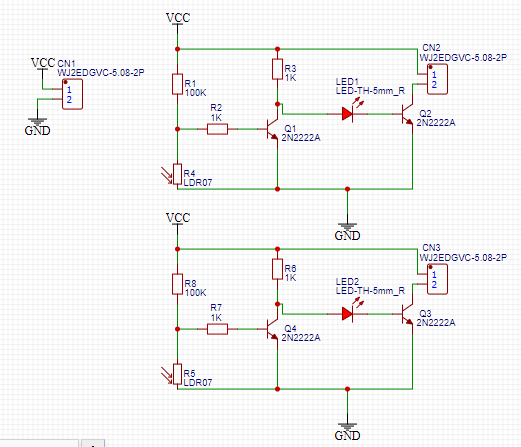
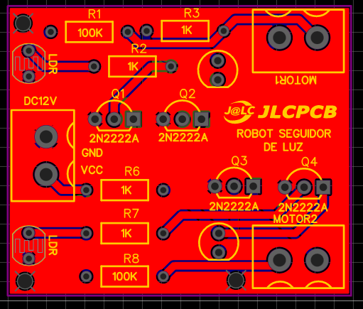
This project is an autonomous system, that is, the LDR sensor, when detecting light, will drive a DC 12V motor and thus achieve movement. In this case we will have 2 sensors and 2 motors that will allow us to move to the right or left following the light.
Firstly, to design this circuit we will have to start knowing how an LDR works, which is very easy and understandable, when the LDR does not detect light its resistance is HIGH and when it detects light its resistance is very LOW, knowing that we can make a divider voltage at the input of the transistor to automatically activate or deactivate the motor.
At the output of the first transistor we will put another one to have the DARLINGTON configuration, this will allow us to increase the current to activate the motor since we need approximately 200 mA for each motor, and thus we solve or prevent the transistors from burning.
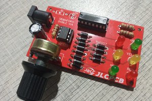
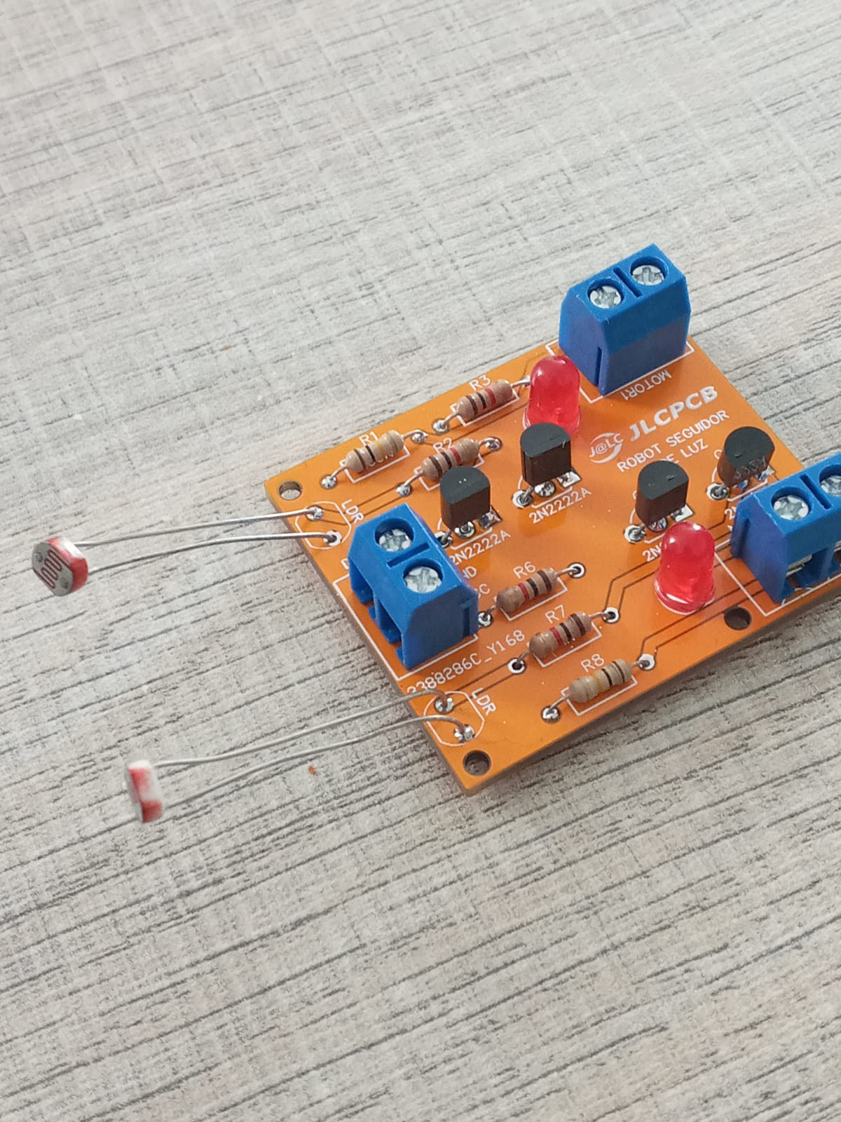
This circuit can be done by getting the necessary components for its operation
ELECTRONIC COMPONENTS:
· 4 TRANSISTORS BJT 2N2222A
· 4 RESISTORS 1/4W 1K
· 2 RESISTORS 1/4W 100K
· 2 LDRs
· 2 LED DIODES 5MM
· 3 BLUE TERMINAL BOARDS 2 PINS
PROJECT FEATURES
· VIN 12VDC
· IMAX 500mA
· 2 OUTPUT 12VDC
· PCB 40mm x40mm
JLCPCB

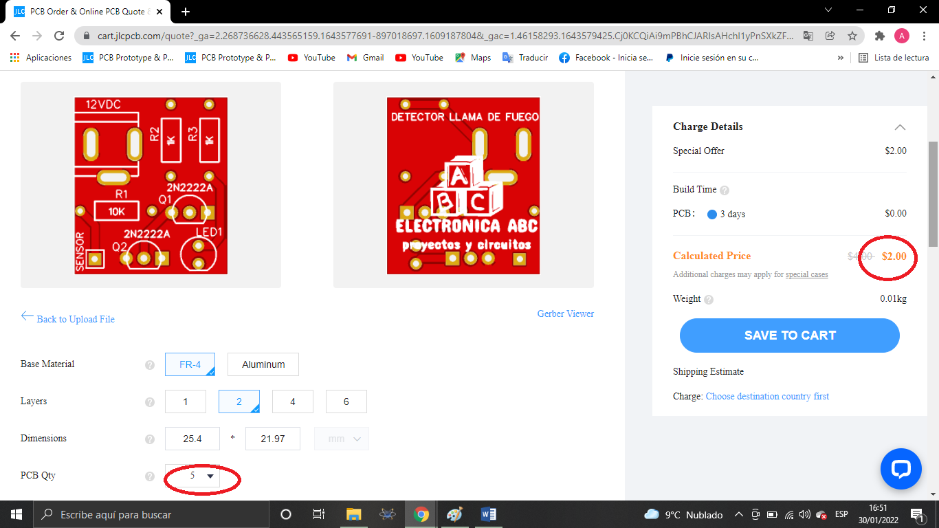
we thank JLCPCB for the professional pcbs you can purchase
5 pcbs a $ 2
order your pcb here:
Gerber:
https://mega.nz/file/zM4HUKrQ#UQoz6jh9dnY1aeTuF_lFwfqFk5nBVBz8lWoU_vE1Yrw
 Cornelius Robinson