Close
0%
0%

Tippy Timer

A simple "box" to make it easier to time out discrete intervals.

Similar projects worth following
This box will have 7 discrete timing intervals: 3, 5, 10, 15, 30, 45 and 60 minutes. The box will be an octahedron (not regular), so the eighth state will be "Off". It uses a low power accelerometer to determine position, and will have a small 128x32 OLED display. When the box is tipped over the side facing up determines the timing interval. When the timer expires it will beep and go to sleep if not interrupted. Yes, I know you can buy one of these on Amazon for not much money, but complexity of such a simple device is a real challenge.

[Edit 2022-06-10: updated Current State of Progress.]

[Edit 2022-04-21: added a section describing the code flowchart and updated the project status.]

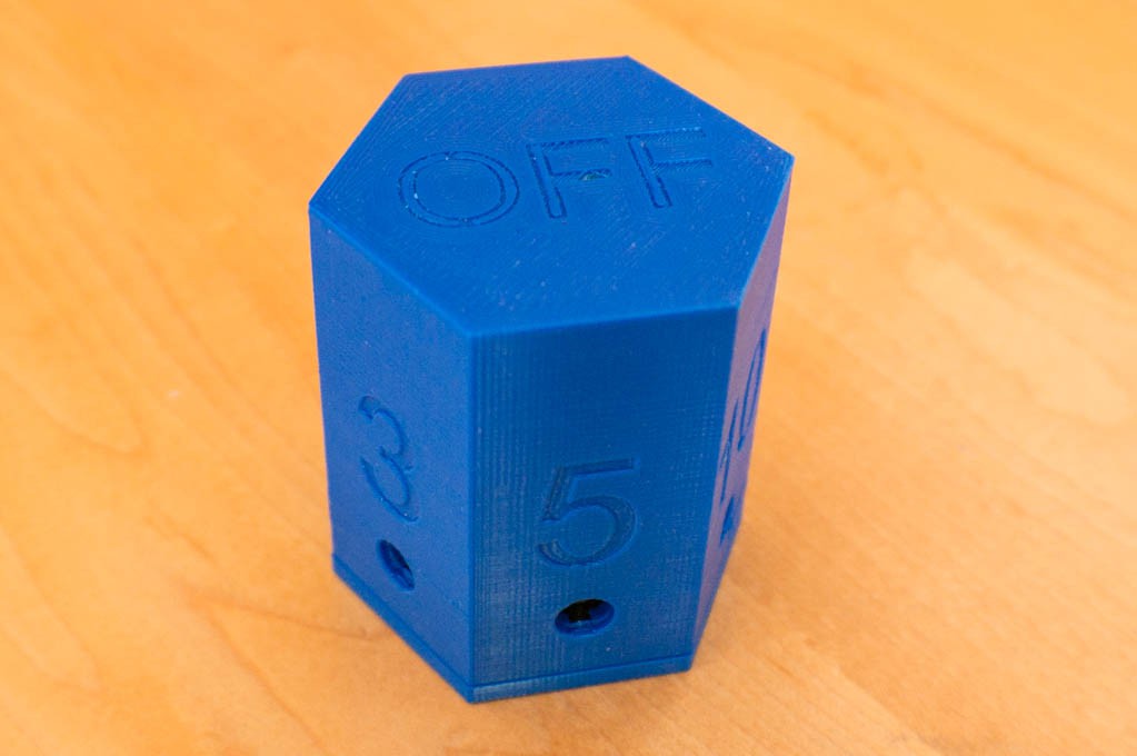
I have a timer cube -- from Amazon -- that will timeout 4 intervals: 1, 5, 10, 15 minutes. You simply tip the cube from the "off" side to one of the labeled intervals and it begins to timeout the interval. When it's done it beeps for about one minute, or until you flip it back to the side that designates "off". There is not much to it...no menus...just an on/off switch (which seems unnecessary.) The cube uses a metal ball (I'm guessing here) that rolls to the lowest point and informs the intelligent circuits which side is downward so that it can time out the interval properly. There is also a 4-digit LCD display that I almost never look at. I use this timer cube most often to let me know when to let Lucy, our Border Collie mix dog, back into the house after a potty break.

I thought it would be a nice simple project to employ some electronic hardware & software, as well as improve my 3D printing expertise, which is in its infancy.

Functionality:

  1. It should be low power since it will have a relatively small battery for power. I'm shooting for an idle current of less than 25uA, and less than 3mA average current when timing an interval. There is no on/off switch.
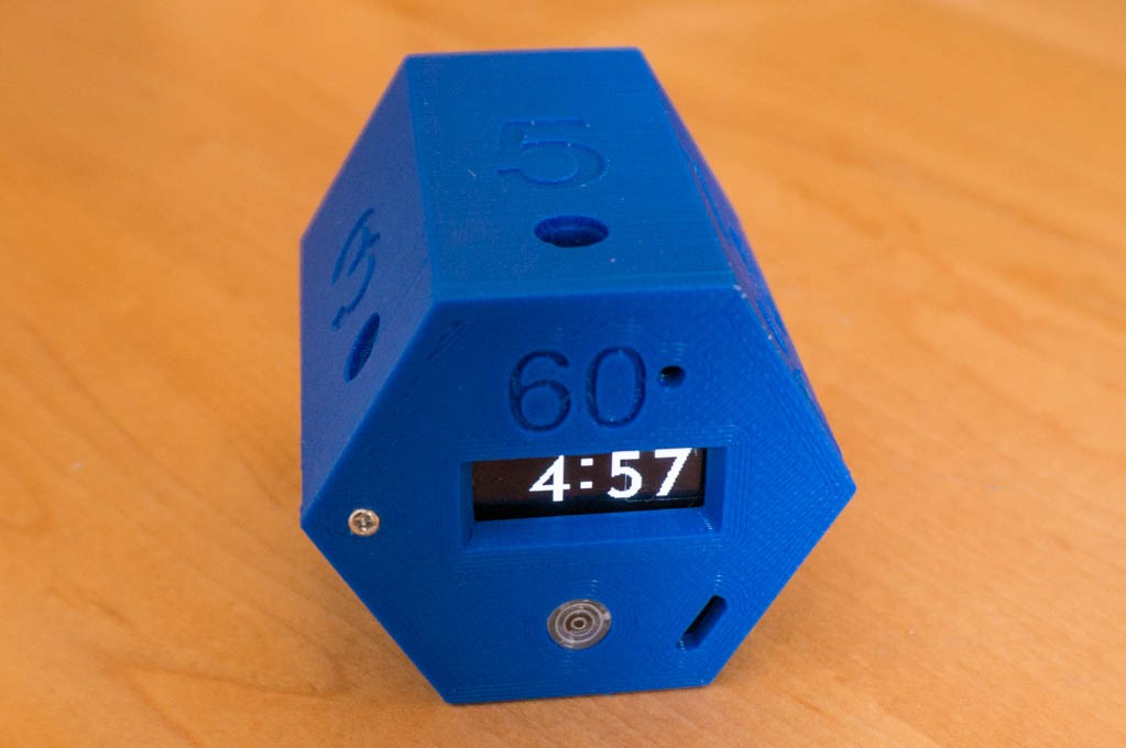
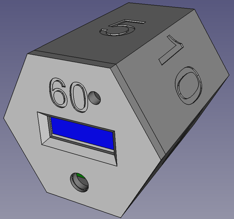
  2. It should begin a timing interval after having it's 3-dimensional position changed. There are seven timing intervals (3, 5, 10, 15, 30, 45 and 60 minutes) and an off state.
  3. The timing interval can be terminated simply by setting the box in the off position. In addition, any timing interval can be changed to another and restarted by tipping the box to a different side.
  4. The box will emit a short beep/tone/annunciation to confirm that it has started the interval.
  5. At the end of the timing interval the box emits 40 beeps/tones/??? until it is set to its off position or the series of beeps expires. 
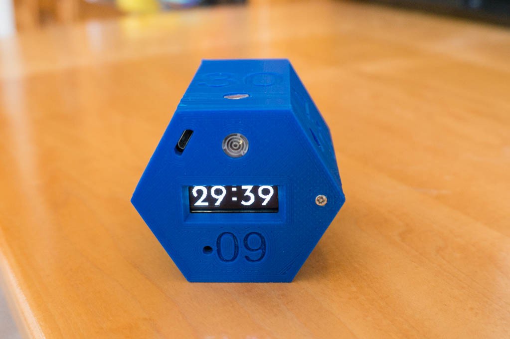
  6. The display will indicate the remaining time left in minutes:seconds. The Off position of the cube has the display face down on a surface, so that all of the timing intervals have a visible display. The display remains oriented so as to be always be "right side up" and readable.
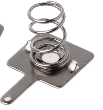
  7. Power is from a single lithium-Ion 10440 (AAA size) rechargeable battery. The battery should be easily replaceable. An internal charger gets 5V nominal power from a micro-USB connector. Recharging a depleted battery should require 1-2 hours, and the unit should have a standby operation of more than one year and be able to time out more than 100 hours per charge.

Other Features in the "It Would Be Nice To Have" Category:

  1. A menu mode to change certain parameters -- like beep volume, etc. This would be and interesting challenge since there are no buttons or switches on the box.
  2. Total cost < $10 USD.

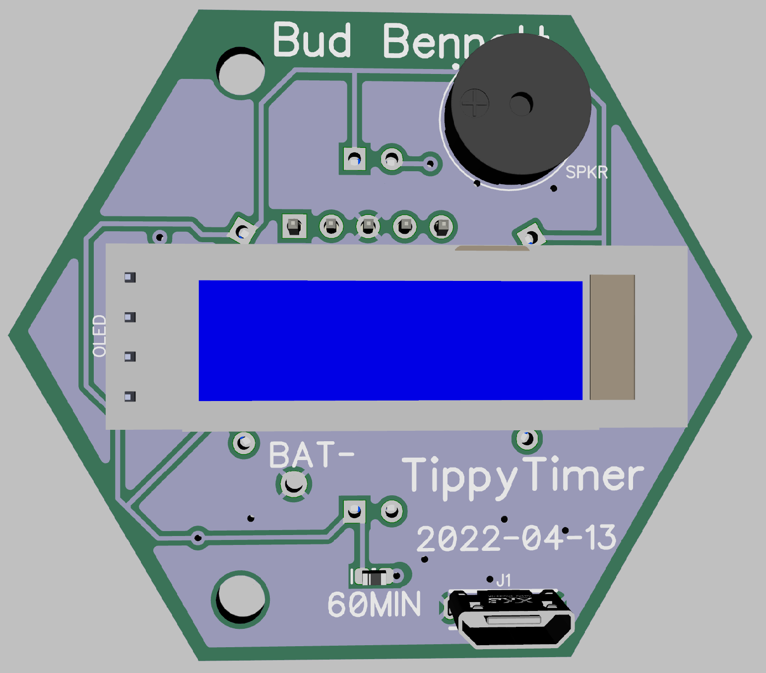
I've settled upon the PIC16F18345 micro-controller: a 20-pin 8-bit part that seems to contain the kitchen sink of stuff that you might need: I2C interface, ADC, PWM for beeper, low current secondary 32768Hz oscillator, timer/counters, 14k of program memory -- all for about $1.5 in low quantities. Here is my current schematic (currently rev.2):

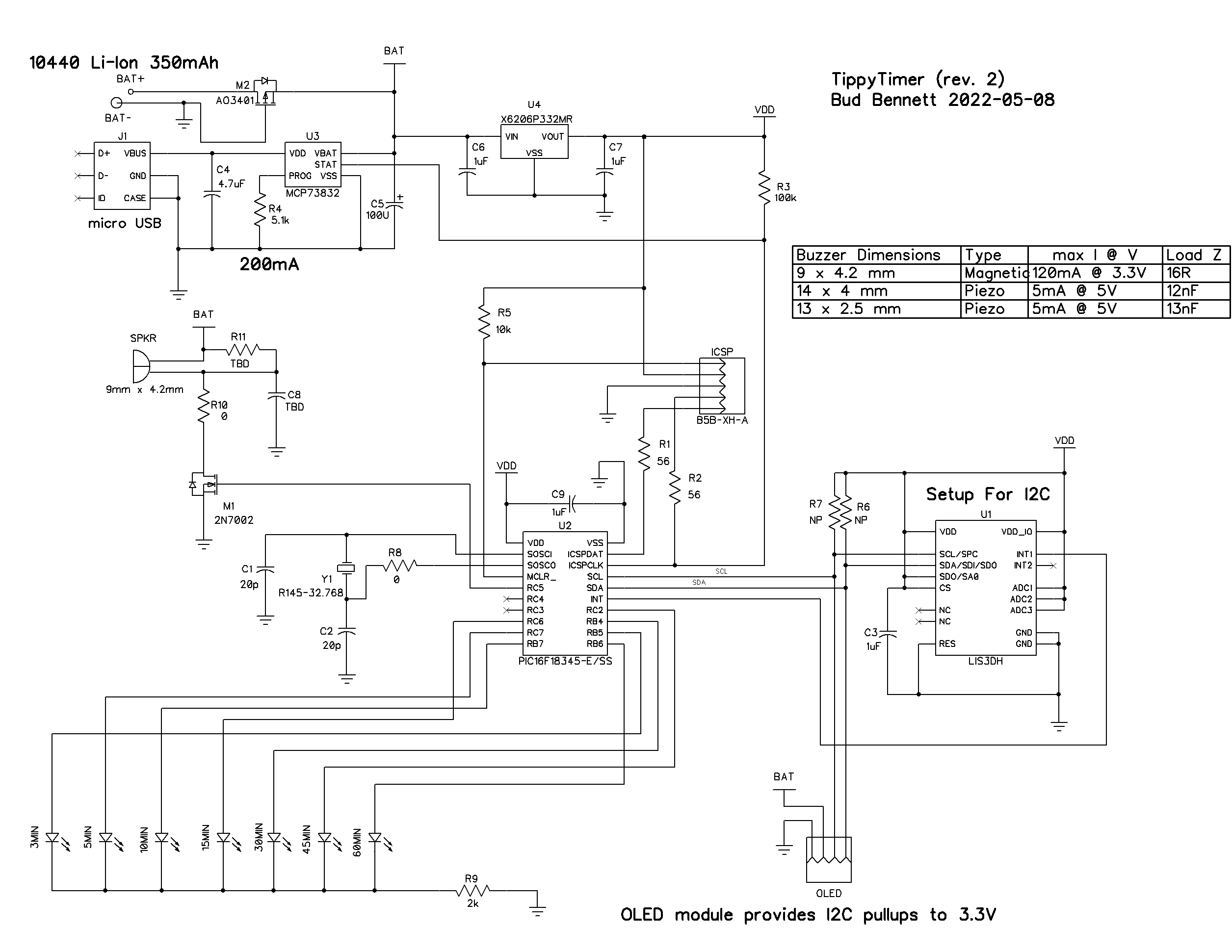
This design uses one AAA 3.7V Li-Ion battery. I have figured out a method to house/contain this battery. I initially intended to use LiPo chemistry, but the system uses a 3.3V regulated voltage for VDD. The PIC's ADC is setup to measure an internal 2.048V input voltage using VDD as the reference. This implies that the PIC won't know what the battery voltage is until it drops below 3.3V. LiPo batteries should not be discharged below 3.5V, hence the switch to Li-Ion since they can be discharged to 2.5V without damage. (Yes, I could have configured the ADC to use an external resistor divider from the battery, but this is more PIC pins, components and potentially more current.)

Instead of a rolling metal ball, I'm using an accelerometer IC -- the LIS3DH -- which is a cheap and low current IC to tell the system what...

Read more »

  • Second Pass PCBs and Firmware Feature Updates

    Bud Bennett06/09/2022 at 20:30 0 comments

    Second pass PCBs were waiting for me after a road trip in May. Rather than using new components to populate the PCB I removed them from the first pass PCB. This caused a few problems with intermittent solder joints, etc. But here's the top side of the second pass board:

    The red wire is just for testing purposes. The footprint for the PIC is a lot easier to solder on this version. After finding and fixing 2-3 bad/missing solder joints I have a fully functional Tippy Timer.

    Loading new firmware took less than a minute. Included in the new firmware was code to indicate a low battery and also when charging the battery.

    It's not perfect. The LOWBAT indicator only displays when a new charging interval begins -- and it overrides the timer function and beeps incessantly. That's probably better than beeping at 2:00am like my smoke detectors.

    The CHARGE indicator flashes every two seconds the entire time that the battery is being charged. When the STAT pin of the charger goes inactive (High) the unit goes to sleep until it is moved to begin another timing interval.

    It's getting close to complete, but I can see a lot more tweaking before it's finished.

    *****************

    The piezo passive buzzers arrived as well. They are a bust. With 4.2V applied to them the beeping was nearly inaudible. So it will be magnetic buzzers going forward.

  • Material Progress

    Bud Bennett05/07/2022 at 21:44 0 comments

    The battery spring contacts, 9x4.2mm passive buzzers and LED windows arrived a couple of days ago. I was able to test out the battery holder concept and the fit/finish of the case. Here's what I have right now:

    There is a single M1.7x6mm screw holding the top to the case bottom. I couldn't figure out how to make it secure with spring-loaded plastic catches -- they kept breaking.

    The battery holder scheme seems to work well. It is a bit difficult to install the spring clip at the bottom of the case. I used a battery to hold it in place while dripping CA glue onto the spring clip and inadvertently glued the battery into the holder. The PIC doesn't always run properly if there is intermittent power application while setting the PCB over the positive battery terminal. This should resolve itself when the watchdog overflows after about 5 minutes -- I'll have to test that.

    The USB charging port hole still needs some relocation to center it better over the connector. Note that the display inverts for the 15/30/45 minute hemisphere so that it is still readable. I have also implemented rudimentary versions of the start beep, end beep, and off beep. The end beep is two recurring short tones that start out quietly (5% duty cycle) and grow with each successive pair of beeps until the box is flipped to a new position or "Off". The end beep series is 30 pairs, which should give the user plenty of notice.

    Still Plenty Left to Do:

    1. Implement LED indicators.
    2. Fine tune the accelerometer parameters for initial position sensing interrupt trigger.
    3. Fine tune the accelerometer parameters for each timer position to avoid false triggers or changes from noise or small disturbances upon the resting surface.
    4. Implement the low battery indicator and charging indicator.
    5. Reduce the thickness of the bezel around the display. The 60 degree bezel doesn't allow the entire display to be viewed at an angle. This should be relatively easy to accomplish by just using the header spacers included with the OLED boards to increase the height of the OLED from the PCB surface.
    6. Stuff that I haven't thought of yet.

  • First Pass PCB Results

    Bud Bennett05/05/2022 at 14:33 0 comments

    I populated one PCB on 2 May, 2022. There were a few surprises. The footprint for the PIC was not wide enough and required very precise hand-soldering to properly register the pins. (Mea culpa...I replaced the proper footprint with a generic 20-pin SSOP without checking the data sheet.) The OLED protruded above the board more than the allowed 5.5mm. This was remedied by removing the plastic spacers on the 4-pin header and placing a piece of double-sided tape at the other end of the OLED board to properly space it. Also, the case opening for the PCB was not large enough, resulting in a very tight fit.

    My usual practice is to solder the LIS3DH accelerometer to the board by solder bumping both the board and the package. Using a generous amount of flux paste, the package is then hot air soldered with an extra tap, or push, to the top of the package to ensure the bumps connect. After that the pins are checked for connectivity by measuring input protection diodes from GND to each pin. Since there are no other components on the board this check is very predictive of a good solder joint. Then the flux is removed.

    Powering up the first time for a new design requires the power supply to be set to a low current. I set the power supply for 3.7V with a 10mA limit. The display was dead. It turns out that the display won't activate if the power supply ramps up too slowly. After I was confident that there were no high current problems with the board the power supply current was increased to 100mA, which solved the OLED startup problem.

    I could verify some preliminary functionality by tipping the board on its side an noting the display value, but it would not count down.

    Secondary Oscillator Problems:

    The 32.768kHz secondary oscillator was not running. I am aware of startup issues with these low frequency crystals and changed the two coupling capacitors from 22pF to 15pF along with several values of R8 with no luck. I returned to the protoboard to try and figure out how sensitive this oscillator was. 

    There appeared to be no problem with components on the protoboard. It wasn't until I swapped out the 3x8mm crystal for a 2x6mm crystal package that I was using on the PCB that the problem became apparent. I had ordered 20 pieces of the 2x6mm form factor crystals from Aliexpress. Half of them tested bad on the protoboard. Apparently the AliExpress seller was selling rejects, which makes me wonder about the quality of the nine crystals that did oscillate.

    When I replaced the bad crystal with a good one on the PCB the oscillator started up and ran properly. The OLED display counts down at a one-second interval.

    Current Drain Data:

    Average current draw in sleep: 30uA

    Average current draw active: ~4mA

    I'm gonna have to track down the source of the high currents during sleep...it's a mission now.

    Functionality:

    The code still reflects what was used for the protoboard version so the orientation of the accelerometer has changed with the PCB mounting. The Off position and 60 minute position are unchanged but all of the others need to be reworked. But the timing interval changes and resets every time the PCB is oriented to a different edge upward. It will take a few more days to find the bugs.

  • Figuring Out the OLED

    Bud Bennett04/16/2022 at 21:04 0 comments

    The OLED display is driven by the SSD1360 IC. The datasheet is available from Adafruit for your viewing pleasure. There is no PIC library that I'm aware of to make it easier to drive the display. The SSD1306 divides the display up into 4 horizontal pages and 128 vertical segments. There are three methods to address the display -- I chose the default method of manually addressing each page and segment. When you send a data byte to the OLED it fills up 8 sequential pixels from the top of the page to the bottom.

    I decided to assign digit locations to 4 areas. The 10 minute digit occupies segments 0-27, the 1 minute digit occupies segments 28-56, etc. The colon gets 16 segments in the middle. Each digit must have the same number of segments to make the coding easier.

    After the mapping was completed I needed to create graphical characters for the 10 digits. First, I created a 28 x 32 grid of the pixels in each digit space. Then I found a font that appealed to me -- Reem Kufi -- scaled up to 600pts and placed each character over the grid with some transparency, so you could still see the grid lines. As so:

    There is a bit more room to the right than to the left to allow for proper spacing. Then I laboriously filled in each byte position for every segment of every page. The result is a large display with fairly crisp characters. I made some small errors along the way that will have to be corrected after the main program is completed.

    Each character, plus an all-zeros blank character, was then transferred into the program memory of the PIC at the end of the program memory space. This requires 1232 bytes of program memory out of a total of 14k bytes. Here's an example of the "2" character:

    Digit2:
        DB    0x00,0x00,0xc0,0xe0,0xf8,0xfc,0xfe,0x7e,0x3e,0x1f,0x1f,0x1f,0x1f
        DB    0x1f,0x1f,0x3f,0x3e,0xfe,0xfc,0xfc,0xf8,0xf0,0xc0,0x00,0x00,0x00
        DB    0x00,0x02,0x3f,0xff,0xff,0xff,0xf4,0xc0,0x00,0x00,0x00,0x00,0x00
        DB    0x00,0x00,0x00,0x00,0xc0,0xff,0xff,0xff,0xff,0x3f,0x00,0x00,0x00
        DB    0x00,0x00,0x00,0x00,0x01,0x03,0x01,0x00,0x00,0x00,0x00,0x80,0xc0
        DB    0xe0,0xf8,0xfc,0xff,0x3f,0x1f,0x0f,0x07,0x01,0x00,0x00,0x00,0x00
        DB    0x00,0x00,0x00,0x80,0xc0,0xe0,0xf0,0xf8,0xfc,0xfe,0xff,0xff,0xff
        DB    0xf3,0xf1,0xf0,0xf0,0xf0,0xf0,0xf0,0xf0,0xf0,0xf0,0xf0,0x00,0x00

    When this is written to the OLED RAM, the Page number and segment start location is set to the digit location and then all 28 bytes are written in a single I2C communication for that page. Then the next Page is written, etc. until all four pages contain the character data for that digit. The other four digits and colon are written similarly. The entire I2C communication for all four digits requires about 220ms.

    This was a lot of effort.

  • From Concept to Development

    Bud Bennett04/14/2022 at 03:56 0 comments

    The schematic and layout are pretty firm. There were a few iterations back and forth to optimize the layout. The PCB has to integrate nicely with the enclosure so a few major decisions were made.

    Battery Holder Mechanics:

    I did not want to use a battery holder, though they're pretty cheap. The extra space for a commercial battery holder would be just wasted. I searched for spring clips to build my own battery holder and eventually settled on these, from AliExpress:

    They are 9mm x 10mm x 6mm high, and about $0.16/pair. They come as a +/- pair, but I don't think I'll need the positive terminal -- the battery positive button will just contact a soldered pad on the PCB. I'll probably just hot glue this piece to the bottom of the battery holder and solder a wire between the tab and the PCB. That will be the only wire connection to the PCB. To replace the battery, the user will have to remove the top cover and the screws holding the PCB to the case. The battery will then just pop out. There is protection for reverse battery, so no harm if the user replaces the battery backward.

    PCB Layout:

    There are 7 LEDs that serve as activity confirmation. They should light up a spot on the face of the enclosure corresponding to the timing interval. This complicates the layout. I'm doubtful that surface mount LEDs could provide enough directional light, so 3mm through-hole LEDs are used instead. The LEDs will be mounted at right angles to the PCB and probably secured with hot-melt glue. This is what the top side of the PCB looks like today:

    Since the LEDs will be mounted at right angles there must be nothing between the leads and the edge of the board. I measured the length from the holes to the top of the LED to be roughly 7mm and added another 3mm to clear any support shelf in the enclosure -- so all of the LED are 10mm from the respective PCB edge.

    You can see where the positive terminal of the battery will butt up into the PCB.  There is plenty of clearance to avoid any mishap with short circuits during assembly.

    The bottom side of the PCB has very few components -- just the speaker, the OLED display, the USB charging port, and the SMD LED for the 60 minute interval. This side faces the top of the enclosure. When the timer is running the display will be visible either from the side (for the 3,5,10,15,30,45 minute intervals) or from the top (for the 60 minute interval.) When the unit is "Off" this side will face down toward the surface it rests upon.

    All of the components on this side should be about the same height. The OLED is about 4-5 mm thick, the speaker is a 9042 passive buzzer that is 4.2mm high, and the vertical USB connector is 5.5mm high. I might reconsider the decision to use a SMD LED because I measures the 3mm through-hole LED to have a height of about 5mm when mounted straight to the board.

    The PCB measures 44mm between the parallel sides. Slightly more than that from the opposite vertices. These dimensions are about the smallest required to fit the OLED with the display centered in the face of the enclosure. The depth of the enclosure must be about 57mm to hold the 10440 battery, the PCB with its components and the enclosure lid.

    Getting the Light Out:

    The enclosure will be fitted with these small "windows" to allow light from the LEDs to be visible while keeping dust and dirt out of the enclosure.

    They are 6.85 mm in diameter, made for 5mm LEDs. They should just pop into holes in the 3D printed enclosure. I will need seven of these for each TippyTImer.

    The Box:

    I've made some progress using FreeCAD to model the enclosure. Here's a view showing the concept so far:

    The LED " window" is at the bottom of the face with the display. I have not yet added the windows to the other faces. The hole at the top left of that face is for the speaker -- I may need to move the speaker a bit further to the outside edge to get it away from the 60 minute label. I haven't yet added access for...

    Read more »

View all 5 project logs

Enjoy this project?

Share

Discussions

Similar Projects

Does this project spark your interest?

Become a member to follow this project and never miss any updates