Close
0%
0%

Night Light Control + PID Battery Charger

PWM Signal Charging the Battery of a "Night Light Control" by Using a PID Controller

Similar projects worth following
Renewable energy is a practical, affordable solution to our electricity needs. By ramping up renewable energy, we can reduce air pollution, cut global warming emissions, create new jobs and industries, diversify our power supply, decrease dependence on coal and other fossil fuels and move the World toward a cleaner, healthier energy future. We intend to create a lighting control system that allows us to save energy. Smart lighting control systems are widely used on both indoor and outdoor lighting of commercial, industrial, and residential spaces. Lighting control systems serve to provide the right amount of light where and when it´s needed, and this project do it!

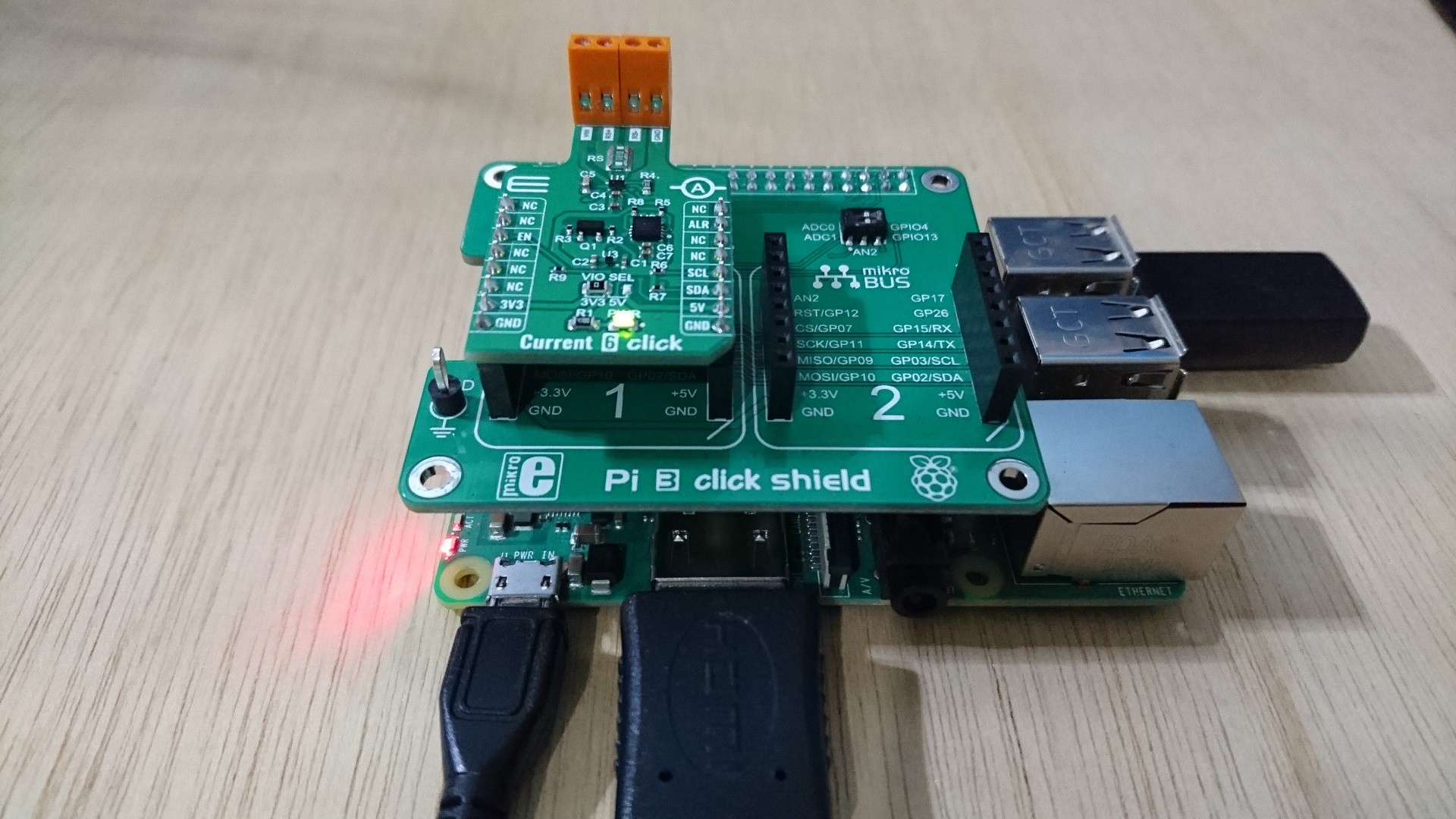
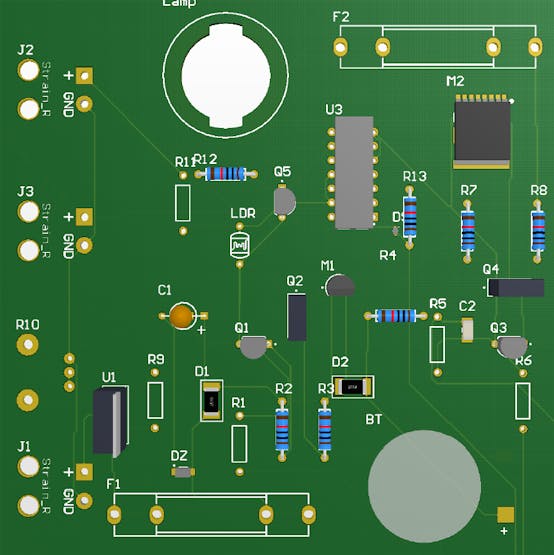
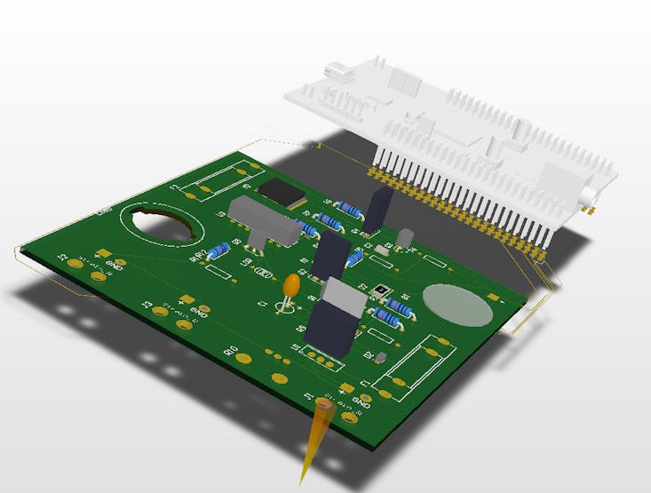
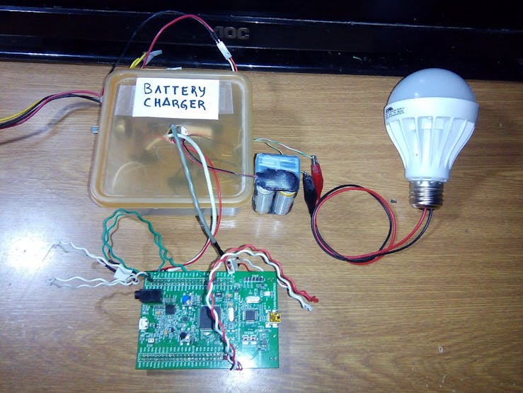
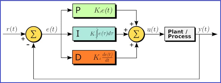
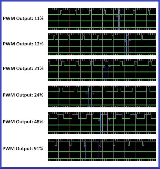
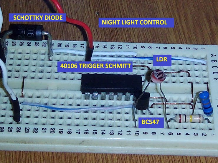
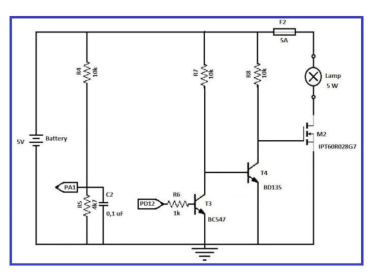
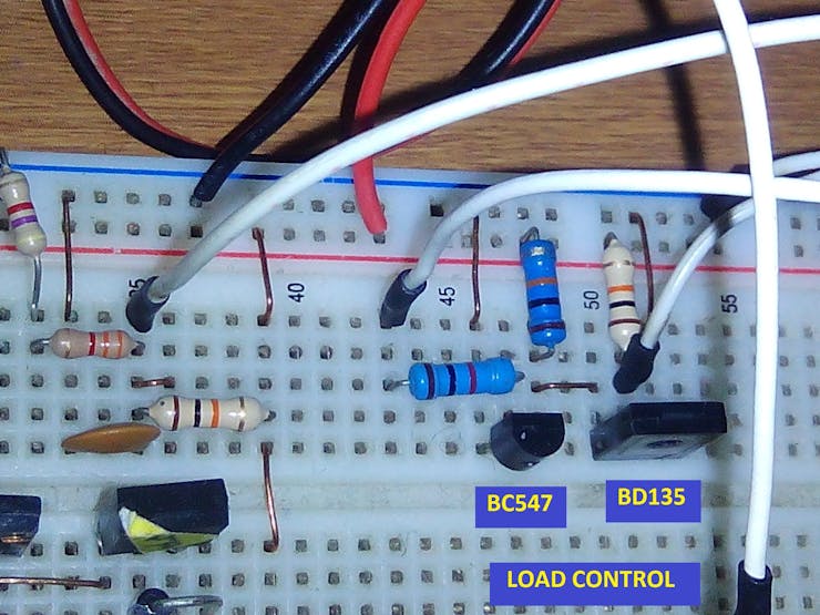
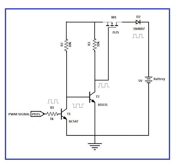
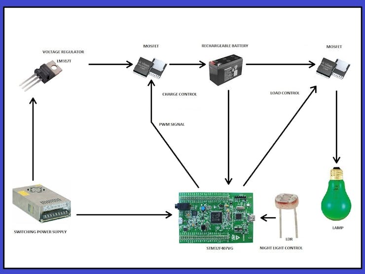
In this project I used different areas of electronics: a) Microcontroller (PWM signals and digital and analog ports); b) Power electronics (Mosfet, battery and lamp); c) Digital electronics (IC Trigger Schmitt); d) Sensors (LDR); and e) Control theory (PID controller).

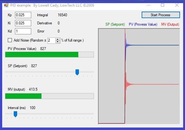
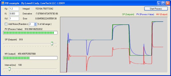
The system went more efficient and practical with the PID controller, since the battery was charged faster and had a longer useful life. This smart night light control is used to activate a lamp at night and charge the battery at day light. This project can serve us as an example in the future to develop a "Street Light Control", with a panel of solar cells or wind energy as I pretend.

diagrams.zip

Diagrams

x-zip-compressed - 822.44 kB - 04/03/2022 at 05:22

Download

x-zip-compressed - 1.20 MB - 04/03/2022 at 05:18

Download

x-zip-compressed - 2.82 MB - 04/03/2022 at 05:16

Download

  • 1 × STM32F407G-DISC1 board
  • 1 × Infineon CoolMOS C7 Gold SJ MOSFET
  • 1 × J525 P-Channel Mosfet (Toshiba)
  • 1 × Linear Regulator with Adjustable Output
  • 1 × BC547 - NPN Transistor

View all 22 components

  • 10. Project Status and Future Plans

    Guillermo Perez Guillen05/01/2022 at 04:11 0 comments

    BIDIRECTIONAL CURRENT-SENSE AMPLIFIER

    At the time of writing this blog post I started experimenting with using Current 6 Click is a very accurate current measurement Click board™, based on the ACS723 IC. This IC is a galvanically isolated current sensor, which utilizes the Hall-effect principle. Its most distinctive feature is its very low series resistance of only 0.65 mΩ, which makes this device a nearly-perfect ammeter.

    Current 6 Click is a compact add-on board providing a precise and accurate current sensing solution. This board features the MAX40080, a fast-response bi-directional current-sense amplifier from Analog Devices. The device features ultra-low 5uV input offset voltage, very-low 0.2% gain error, and includes an analog-to-digital converter with programmable sample rate and 12-bit resolution featuring I2C compatible interface. It also features a wake-up current-threshold and auto-shutdown mode when the I2C is inactive, both designed to minimize power consumption. The current-shunt monitor can measure voltage signals on common-mode voltages ranging from -0.1V (ground sensing) to 36V, independent of the supply voltage. This Click board™ delivers higher performance to industrial control and automation applications, load and power supplies monitoring, telecom equipment, and many more.

    Many current-sense applications require bidirectional current-sensing capabilities. For instance, when a laptop is plugged into an AC power line, the AC adapter supplies power to the laptop and charges the battery. The battery's charge current is monitored to ensure that the battery does not overheat and that the total input power drawn from the AC adapter does not exceed UL-mandated limits. Similarly, the battery discharge current is monitored for fuel-gauging/active power management on the load device when the AC adapter is not available and battery capacity needs to be conserved. Figure below shows a typical current-sense amplifier implementation in a battery-charging/-discharging application.

    SOLAR PANEL CHARGER

    I also have plans to add commercial solar panels to this system like the one shown below.

    This solar panel charger is a lightweight, ultra thin (2mm), and affordable power solution. This panel comes with a 5V USB connection port. The panel is capable of 10 watts in the open sun with a peak power output around 6V at 1700mA. This panel features a monocrystalline silicon material to provide a 20% high photoelectric conversion rate. With a frosted surface makes the panel scratch resistant and more durable. This also has a water resistant epoxy resin seal. The panel is slightly flexible making it considerably lighter than equivalent glass based panels. Because it is light weight this panel is designed for temporary installation on windows (that's what the included suction cups are for) but can be permanently installed. This panel weighs 3.3648 ounces and measures 259.60mm x 139.69mm x 2.46mm (9.83mm thickness at the USB port).

    LAST WORDS

    • After first experiments I faced some issues that cost me a lot of time and I also found some mistakes in datasheet which I will report to provider bidirectional current sensor Maxim. I am currently testing my own library and I plan to post some first thoughts soon. 
    • I am still waiting my solar panels for my more advanced experiments, since I just have one piece to make simple tests. In the meantime, I ordered and received required components.
    • For this blog it is totally all. Thank you for reading it and stay tuned. If you find any inconvenience or other issue in my formulas, computation or somewhere else, feel free to write a comment. I also like to hear any feedback.

  • 9.- Circuit Board Designs

    Guillermo Perez Guillen04/03/2022 at 05:08 0 comments

    The schematic circuit was made on CircuitMaker. You can find the repository in the Custom parts and enclosures section.Project repository: "Circuit Board Designs of PID Battery Charger With Night Light Control"

    Circuit diagram developed CircuitMaker

    Circuit diagram developed CircuitMaker

    PCB 2D developed CircuitMaker

    PCB 2D developed CircuitMaker

    PCB 3D developed CircuitMaker

    PCB 3D developed CircuitMaker

    Orthogonal rotation view powered CircuitMaker

    Orthogonal rotation view powered CircuitMake

  • 8.- Tests of the First Prototype

    Guillermo Perez Guillen04/03/2022 at 05:01 0 comments

    Assembly of parts

    Next, I show you some images of the assembly.

    Soldering

    Soldering

    Protecting the board in a box

    Protecting the board in a box

    The prototype is finished

    The prototype is finished

    Test

    Generating a PWM signal: This example requires a setpoint and the PWM signal is generated automatically.

    Analysys

    Generating a control PWM signal from a PIDController:

    Setpoint: VBattery = 4.95 volts / VR5 = 2, 2 volts / ADC = 3003 ADC.

    We can appreciate, here the PID controller, generates many duties cycles.

    Measured frequency = 30 kHz

    Measured frequency = 30 kHz

    VR5 = 2,2 volts, duty cycle = 11%

    VR5 = 2,2 volts, duty cycle = 11%

    VR5 = 1,99 volts, duty cycle = 12%

    VR5 = 1,99 volts, duty cycle = 12%

    VR5 = 1,6 volts, duty cycle = 21%

    VR5 = 1,6 volts, duty cycle = 21%

    VR5 = 1,3 volts, duty cycle = 24%

    VR5 = 1,3 volts, duty cycle = 24%

    VR5 = 1,13 volts, duty cycle = 48%

    VR5 = 1,13 volts, duty cycle = 48%

    VR5 = 0,9 volts, duty cycle = 91%

    VR5 = 0,9 volts, duty cycle = 91%

  • 7.- Generating a Control PWM Signal from a PID Controller

    Guillermo Perez Guillen04/03/2022 at 04:31 0 comments

    In this test, we are going to use a different program. You can find the program in the Code section. Project repository: "PID Battery Charger With Night Light Control"

    How does it work?

    a) If we want to take control of a system, the best solution is to make use of the PID control. PID is a control loop feedback mechanism widely used in industrial control systems and a variety of other applications requiring continuously modulated control. A PID controller continuously calculates an error value as the difference between a desired setpoint (SP) and a measured process variable (PV) and applies a correction based on proportional, integral, and derivative terms (denoted P, I, and D respectively), hence the name.

    PID controller

    PID controller

    In my case, STM32F507 board generates a PWM signal of 30 kHz, and the control data are: dt = 0.0005, Kp = 0.025 and Ki =0.025. You may notice that the derivative term is very small or null., and the simulation of my PID controller is the following:

    Using the Lowell Cady program, to test my PID controller.

    Using the Lowell Cady program, to test my PID controller.

    https://en.wikipedia.org/wiki/PID_controller

    b) The work of deciding when to apply a PWM control signal is left to the STM32F407 board. In my example, this board does the calculations and generating the PWM control signal. With my PICkit2 device, I got the following PWM signals.

    The PID controller generates many duty cycles, and these depend on the feedback.

    The PID controller generates many duty cycles, and these depend on the feedback.

    c) The voltage divider VR5 delivers an analog value to our port PA1, and this is compared to the "setpoint". The "setpoint" is programmed by code and we did one setpoint test: VBattery = 4.95 volts / VR5 = 2, 2 volts / ADC = 3003 ADC.

      declare
         Value     : Percentage;
         Raw1      : Long_Float;
         setpoint  : constant := 3003.0; -- VR5 = 2.2 volts / Vbat = 4.95 volts 
         error     : Long_Float := 0.0;
         output    : Long_Float;
         integral  : Long_Float := 0.0;
         dt        : constant := 0.0005;
         Kp        : constant := 0.025;
         Ki        : constant := 0.025;

    d) For example, If the battery is discharged, then the program calculates the error, and generates a PWM signal with a high duty cycle. If the battery is charged, then the program generates a PWM signal with a small duty cycle.

     begin
            STM32.User_Button.Initialize; -- btn instruction
         loop
            Start_Conversion (Converter); --adc instruction
            Poll_For_Status (Converter, Regular_Channel_Conversion_Complete, Successful); --adc instruction
            Raw := UInt32 (Conversion_Value (Converter)); -- reading PA1
            Raw1 := Long_Float(Raw * 1);
            error := (setpoint - Raw1);
            integral := (integral + (error*dt));
            output := ((Kp*error) + (Ki*integral));
            Value := Percentage (output); -- duty cycle value
            if Value < 10 then -- if the duty cycle < 10%
               Power_Control.Set_Duty_Cycle (10);
               Red_LED.Set; -- Red LED os ON
               Green_LED.Clear; -- Green LED is OFF
               Orange_LED.Clear; -- Orange LED is OFF
               delay until Clock + Milliseconds (500); -- slow it down to ease reading                                    
            elsif Value >= 90 then -- If the duty cycle > 90%
               Power_Control.Set_Duty_Cycle (90);
               Red_LED.Clear; -- Red LED is OFF
               Orange_LED.Set; -- Orange LED is OFF
            elsif STM32.User_Button.Has_Been_Pressed then -- If PA0 is ON
               Green_LED.Set; -- Green LED is ON
            else -- If the duty cycle is from: 10 - 90 %
               Power_Control.Set_Duty_Cycle (Value); -- PWM signal
               Orange_LED.Set; -- Orange LED is ON
               Red_LED.Set; -- Red LED is ON
            end if;
            delay until Clock + Milliseconds (10); -- slow it down to ease reading
         end loop;
    

     Now we have an intelligent system that has the advantage of generating many duty cycles, and we will make a more efficient use of energy.

    These are examples of the values obtained with the PID controller

    These are examples of the values obtained with the PID controller

  • 6.- Night Light Control

    Guillermo Perez Guillen04/03/2022 at 04:30 0 comments

    Circuit diagram of the night light control

    Circuit diagram of the night light control

    How does it work?

    a) This “Night Light Control” serves us, to know if it´s day or it´s night and activate the lamp. This circuit is powered with 5 volts from the STM32F407VG board.

    b) To take control of the lighting we´re making use of a photoresistor or LDR sensor. A photoresistor is made of a high resistance semiconductor. In the dark, a photoresistor can have a resistance as high as several megohms (MΩ), while in the light, it can have a resistance as low as a few hundred ohms. https://en.wikipedia.org/wiki/Photoresistor

    c) When there is total darkness, the LDR sensor has maximum resistance (meghoms), the T5 transistor is polarized and at it´s output we have minimum voltage, and at the output of the inverter circuit (IC40106) we have 5 volts. The IC40106 is a Trigger Schmitt inverter circuit. In the following figure we can appreciate how a non-inverter circuit works, which helps us to understand how the inverter circuit 40106 works. These circuits are useful when you want to take control of a digital circuit with signals that are not digital.

    Signals of a photoresistor and a non-inverter circuit

    Signals of a photoresistor and a non-inverter circuit

    Values of VT and VT- for the 40106 (all values are in volts)

    Typical values of a Trigger Schmitt

    Typical values of a Trigger Schmitt

    d) We convert this 5 volts to 3 volts by means of a Schottky diode as shown in the circuit and we apply this voltage to the PA0 pin of our STM32F407VG board.

    e) When there is maximum illumination, then the opposite happens. The LDR sensor has minimum resistance, the T5 transistor isn´t polarized and at it´s output we have the 5 volts of Vcc, which enter through pin 9 of the IC40106 inverter circuit. Finally we have 0 volts, which are applied to the PA0 pin of the STM32F407VG board.

    f) To drive the cutt-off and saturation regions to our T5 transistor, we make the following considerations:

    To determine the saturation current, we consider the emitter collector voltage of the output grid equal to zero. Thus: IC=VCC/RC

    To determine the cutt-off, we consider that the base current is equal to zero, therefore the collector current is equal to zero: VCE=VCC

    g) On the PA0 pin of the STM32F407VG board, when we have zero volts, then the red LED lights up and the lamp turns off. When we have 5 volts the green LED turns on and the lamp turns on.

    You must ensure that the photoresistor is free of obstacles to detect light

    You must ensure that the photoresistor is free of obstacles to detect light

  • 5.- Load Control

    Guillermo Perez Guillen04/03/2022 at 04:28 0 comments

    Circuit diagram of the load control

    Circuit diagram of the load control

    How does it work?

    a) Resistors R4 of 10K and R5 of 8K serve us as voltage dividers to measure the charge of the rechargeable battery with our STM32F407VG board. The 8K resistance is achieved with two resistors in series: 4k7 + 3k3. The value of VR5 we obtain it by means of the calculation of a voltage divider, this would be: VR5=(R5/(R4+R5))*VBattery)

    b) When the PD12 pin of the STM32F407VG board is up, then the transistor T3 drives and is out of phase 180 degrees. Transistor T4 corrects transistor T3 and puts the original signal in phase with the PD12 pin.

    c) To drive the cutt-off and saturation regions to our T3 and T4 transistors, we make the following considerations:

    To determine the saturation current, we consider the emitter collector voltage of the output grid equal to zero. Thus: IC=VCC/RC

    To determine the cutt-off, we consider that the base current is equal to zero, therefore the collector current is equal to zero: VCE=VCC

    d) When the pulse arrives at the "Gate" pin of the IPT60R028G7 Mosfet, then the circuit between "Source" and "Drain" is closed and the 5-watt lamp is turned on. This MOSFET transistor enters the saturation zone when the voltage between the Drain and the Source (VDS) exceeds a fixed value called saturation voltage (Vds sat). That is to say; the MOSFET will be in this region, when:

    VGS > VtVDS > (VGS – Vt).

    In the technical sheets of the IPT60R028GT we see that:

    Gatethreshold voltage

    V(GS)th Minimum = 3

    V(GS)th Typical = 3.5

    V(GS)th Maximum = 4 V

    Therefore, we require 3 to 4 volts in "Gate" to put the Mosfet IPT60R028GT in the saturation region.

    e) The protection devices used are the following: Capacitor C2 and Fuse F2.

    We control the load of a lamp by means of a N-channel MOSFET, and two transistors

    We control the load of a lamp by means of a N-channel MOSFET, and two transistors

  • 4.- Charge Control

    Guillermo Perez Guillen04/03/2022 at 04:26 0 comments

    Circuit diagram of the charge control

    Circuit diagram of the charge control

    How does it work?

    a) The voltage measured in Vcc in this circuit with the voltmeter indicated 5, 45 volts. In this example I´m using a module of four rechargeable batteries of 1, 5 volts. The maximum load voltage will be 5.6 volts. I used Nickel Metal Hydride Batteries, and we can find the international standards here: https://www.mpoweruk.com/standards.htm

    b) The PWM signal generated by the STM32F407VG board will be used to regulate the load that goes to the rechargeable battery. To generate this PWM signal, we take the example "demo_timer_pwm" from "Ada Drivers Library" and modify it to obtain our desired PWM signal. For example, if the battery is completely discharged, then the PWM signal has a large duty cycle.

    c) Transistor T1 was used to physically separate the STM32F407VG board and the M1 Mosfet. If they were directly connected, then this device would be damaged, since the Mosfet works with very high loads. The resistance R1 (1k) must be of a low value to increase the switching speed of the PWM signal.

    d) However, at the output of transistor T1 we have an out-of-phase signal 180 degrees, and to adjust this situation, we make use of transistor T2, and now the PWM signal is in phase.

    e) To drive the cutt-off and saturation regions to our T1 and T2 transistors, we make the following considerations:

    Common emitter

    Common emitter

    To determine the saturation current, we consider the emitter collector voltage of the output grid equal to zero. Thus:

    VCC=IC*RC+VCE | VCC=IC*RC+0

    IC=VCC/RC

    To determine the cutt-off, we consider that the base current is equal to zero, therefore the collector current is equal to zero:

    VCC=IC*RC+VCE | VCC=0*RC+VCE

    VCE=VCC

    Graph of the cut-off and saturation region of a common emitter amplifier

    Graph of the cut-off and saturation region of a common emitter amplifier

    f) The protection devices used are the following: Capacitor C1 and Diode D2. The diode serves to eliminate the reverse direct currents of the battery when it is fully charged. If this diode didn´t exist, then the battery would induce voltages in the transistors T1 and T2.

    We control the charge of a rechargeable battery by means of a P-channel MOSFET, and two transistors

    We control the charge of a rechargeable battery by means of a P-channel MOSFET, and two transistors

  • 3.- Power Supply

    Guillermo Perez Guillen04/03/2022 at 04:24 0 comments

    Circuit diagram of the power supply

    Circuit diagram of the power supply

    How does it work?

    a) The switching power supply provides a stable voltage of 12 Volts DC, 5 Amps and a maximum power of 330 watts. With this device, we will find good stability of the system and we have to adjust the voltage load with which we want to charge our battery and using a potentiometer (R10). We can consult international standards here: https://standards.ieee.org/standard/765-2012.html

    b) The integrated circuit LM317 was used to generate a voltage regulated from 3 to 12 volts by means of potentiometer R10. The technical specifications of this integrated say that it can´t generate less than 3 volts. In this example, I adjust 5.6 volts. The calculations are:

    In the technical sheet of LM317 we find the following formula:

    Vout =Vref [1+(R2/R1)] +(iADJ)(R2)

    For example, the maximum voltage that the LM317can works is 37 Volts, and if in our diagram we take R9 as 240 ohms, then we do the calculation for R10.

    Vout =Vref [1+(R10/R9)] +(iADJ)(R10)

    We consider a very small value of iADJ, and if we calculate R10, we would have:

    R10 = (R9/Vref) (Vout -Vref)

    R10 = (R9/1, 2) (Vout - 1, 2)

    R10 =(240/1, 2)(37-1, 2) = 7, 160 ohms

    And for practical uses, we use a 10k potentiometer.

    c) The Zener diode DZ serves as a voltage regulator and at it´s output I obtained a maximum of 10.8 volts, which I measured with a voltmeter.

    d) The protection devices used are the following: Fuse F1, Capacitor C1 and Diode D1. These elements are very important to protect the system against short circuits, discharges, elimination of reverse direct currents and filter against unwanted signals.

    Be careful with the connections of the LM317T regulator and the Zener diode

    Be careful with the connections of the LM317T regulator and the Zener diode

  • 2.- Software Installation

    Guillermo Perez Guillen04/03/2022 at 04:18 0 comments

    I used the Windows 10 operating system at 32 bits and the software installation is as follows:

    a) I have installed "GNAT Programming Studio", and we can download it from the following link: https://www.adacore.com/download/more

    In this link I have downloaded and installed the following two programs:

    GPS Logo

    b) We have to install the USB driver of the STM32F407VG board, the link is as follows: https://www.st.com/en/development-tools/stsw-link009.html#getsoftware-scroll. On this site we download the following file: "en.stsw-link009.zip". Once connected the device we verify that it is connected in "Device Manager".

    Verifying the installation of the USB driver

    Verifying the installation of the USB driver

    c) To develop this project we work with "Ada Drivers Library", and we can download it from the following link: https://github.com/AdaCore/Ada_Drivers_Library

    To design my project, I used the following examples: "demo_timer_pwm", "demo_adc_polling" and "demo_gpio_direct_leds". The folders you can find here: https://github.com/AdaCore/Ada_Drivers_Library/tree/master/arch/ARM/STM32/driver_demos

    d)CircuitMaker is electronic design automation software for printed circuit board designs targeted at the hobby, hacker, and maker community. The installation software you can download it in: https://circuitmaker.com/

    Designing a schematic diagram and the PCB board

    Designing a schematic diagram and the PCB board

    e) PID example By Lowell Cady, is a working example of a PID (Proportional, Integral, Derivative) control and you can download here: https://www.codeproject.com/Articles/36459/PID-process-control-a-Cruise-Control-example

    Program to test and graph a PID system

    Program to test and graph a PID system

  • 1.- Introduction

    Guillermo Perez Guillen04/03/2022 at 04:14 0 comments

    As main goals, I have two things in mind:

    • Generating a control PWM signal from a PID controller.
    • Add a Night Light Control.

    Applications: “Night Light Control” in our home, business or even on public roads or “Street Light Control”. It can also be used to charge 3V, 5V and 12V batteries.

    STM32F407G-DISC1 Configuration

    STM32F407VG board

    STM32F407VG board

    • STM32F407VGT6 microcontroller featuring 32-bit ARM® Cortex®-M4 with FPU core, 1-Mbyte Flash memory, 192-Kbyte RAM in an LQFP100 package
    • On-board ST-LINK/V2 on STM32F4DISCOVERY or ST-LINK/V2-A on STM32F407G-DISC1
    • USB ST-LINK with re-enumeration capability and three different interfaces: Debug port, Virtual Com port, and Mass storage.
    • Board power supply: through USB bus or from an external 5 V supply voltage
    • External application power supply: 3 V and 5 V
    • LIS302DL or LIS3DSH ST MEMS 3-axis accelerometer
    • MP45DT02 ST-MEMS audio sensor omni-directional digital microphone
    • CS43L22 audio DAC with integrated class D speaker driver
    • Eight LEDs
    • Two push-buttons (user and reset)

    Complete schematic diagram

    As we can see in the schematic diagram, this system mainly performs two functions: first it´s dedicated to charge the battery, and once fully charged, then turn on or off a lamp by means of a LDR light sensor, if it´s at night turn on the lamp and if it´s daylight, turn it off. 

View all 10 project logs

View all instructions

Enjoy this project?

Share

Discussions

Similar Projects

Does this project spark your interest?

Become a member to follow this project and never miss any updates