vishal soni
BCD Watch (binary coded decimal)

Hi,
How are you? I hope everything is going well.
Check out my youtube for more amazing projects.
There are lots of watches available in the market, like analog, digital, smart watches etc. So I decided to make a BCD watch. You can make this watch or buy it on tindie.
Buy Link :- https://www.tindie.com/products/vishalsoniindia/bcd-watch-binary-coded-decimal/

What is BCD?
The full form of BCD is binary coded decimal, as its name the binary digits is showing decimal value. It is a very simple representation of decimal numbers in different ways, so you can google BCD or binary coded decimal on google.
Why did I make this?
I want to make a watch which has led, so instead of a simple watch I came with a unique idea. This watch shows time in binary digits. In my engineering I have learned about binary coded decimals, I think some schools also teach this. This unique way of time representation is not easily understood by normal users.
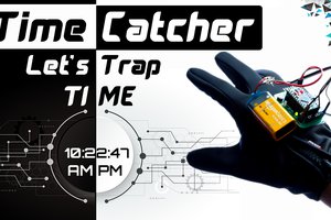
Functionality

There is a single button in the controller, if you press the button it will show hours and minutes in one second of delay as shown in the image. When it show hours the re led on the top will glow and when it shows minutes the minute led on the top will glow.
When you long press the button it will go in to setting mode,
Firstly the hour led will blink means it is in hour setting mode, the hours can be increased by pressing the button.

When you long press the button again it will go in minutes setting mode, the minute led will start blinking. The minutes can be increased by pressing the button.
Now to come out from setting mode long press the button again, after long pressing it will show normal hours in minutes with one second of delay as before.
PCB design

Firstly I have designed the schematic in kicad software, i have used attiny85 as our controller.
There is not much pinout in attiny85 so i have used 74HC595 shift resistor, it increased pinout for leds. I added a button to show time and set the time. For charging I have used a TP4056 circuit which will handle the charging off of the li-po battery.

After making the schematic I have routed it on a PCB, as you can see the PCB is round shaped with two slots on it, the slot is to insert the belts for our watch.

Kicad has a 3d viewer of the PCB, So we can verify what our PCB will look like and all components and vias are placed at the correct place. You can export this stl file to further use in 3D modeling.
All the PCB files are open source and can be downloaded from my github page.
Github link :- https://github.com/vishalsoniindia/BCD-Watch
PCB order

The PCB is sent by PCBWay, the quality of PCB is awesome, they did a very good job to cut the edge of pcb perfectly.

To order PCBs from PCBWay go to the link :- https://www.pcbway.com/
Then upload the gerber file, you can get the gerber file on my github page.
Soldering Front of PCB

Firstly, I soldered the LEDs and resistors. To solder the LED, solder one leg of led then solder another leg of led, this concept will apply to all SMD components.
After Soldering LED I soldered ATtiny85. First, I soldered one leg of ATtiny85 to fix it in place, then soldered the other 7 legs. Then I soldered the button with the same concept.
Charging and LDO
For Charging circuit I have used the TP4056 which is a charging ic, it handles the constant current charging for li-po and li-ion batteries.
Here I did a hack, I have desoldered the TP4056 ic from the module, also extra components like prog resistor and LED. It saved me the cost of buying a new IC.

Then I soldered the TP4056 circuit on the pcb, also here I used a LDO, to regulate the battery voltage to 3.3v, drive the attiny85 and shift resistor.
Shift Resistor

Here i did a mistake, i did not checked the pads of IC and used wrong foot print of shift resistor,
I am using a 74HC595 shift resistor.

So I decided to...
Read more »
 Jithin Sanal
 Fabrizio
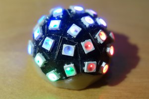
 Erik Bosman