 Lithium ION
I am working on IR protocol in university research Centre and then an idea of IR jammer comes into my mind. So, I tried that on google and find a lot of circuits but the problem is which one is in working condition. That’s why I tried to make my own using the 555 timer ic in astable mode.
As we know from the previous projects and research the remote-control NEC protocol use 38-40khz carrier signal which contains the actual information of the data also. So, we will be going to make our ow using this concept and then place it in front of TV/ any IR receiver to keep it busy. This project is sponsored by PCBWAY and you can get my PCB designs from below. Get your best PCB prototype in just $5 for 5 pcs of double layer boards.
Project Idea:
I decoded my remote values using NEC protocol and then by oscilloscope and I found a 38khz signal on the output of IR led. This signal also has some data value which will make the corresponding changes on the receiver end.
But we can modify the circuit little bit only by sending the blank 38khz signal to receiver. This will keep the IR receiver busy in transmission and doesn’t give opportunity to actual remote to communicate with the receiver. The blank signal can be generated using the 555 timer IC in Astable multi-vibrator mode.
Astable multivibrator in 555:
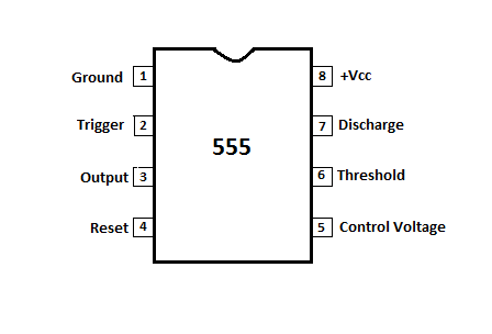
As we can see the DIP package of 555 IC, in the astable multi-vibrator can provide any desirable frequency range under 555 capabilities without any external trigger pulse. So, it is a free running self-triggered mode rectangular oscillator circuit. This one has two quasi stable states (high and low). Frequency and duty cycle can be adjusted using 2 resistor and capacitors.
Basic circuit diagram:
Here in the circuit diagram 100k resistor is R2 and 1K resistor is R1. C is the electrolytic capacitor connected at pin 2 of the IC.
Time for the output should be high: 0.693*(Rt1+Rt2) *Ct
Time for the output of oscillator is low: 0.693* Rt2*Ct
Components required:
1) NE 555 timer ic
2) IR transmitter LED
3) 220R, 2K and 18K resistor
4) 10k Potentiometer
5) 10nf capacitors
6) Tactile switch
7) 9v battery
8) Custom PCB from PCBWAY
Circuit diagram:
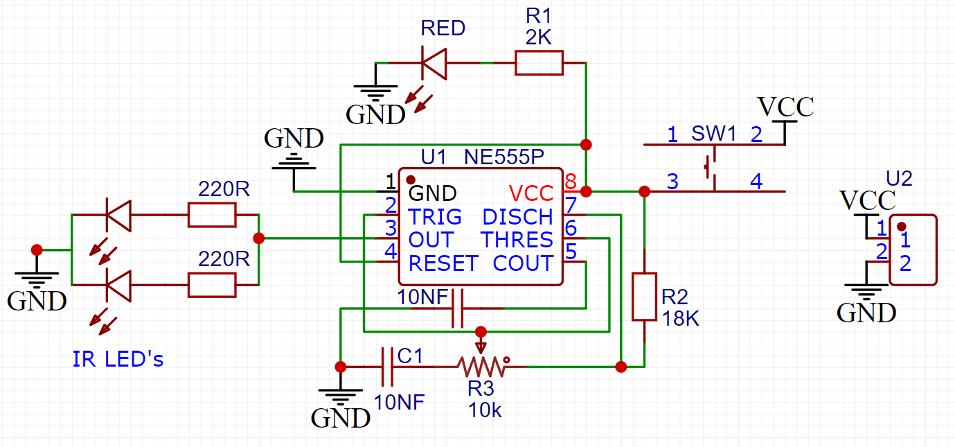
This is the modified circuit layout designed by me and here I made few changes in the basic layouts are: 2 transmitter Led's are used with 220ohms current limiter resistor to the output of 555 timer. This is the square wave oscillator and the time for which the output is high can be determined using the resistor 18k and 10nf capacitor. This circuit can be powered using 9v dc battery through a tactile switch.
The square wave frequency can be adjusted using the 10k potentiometer. which helps to adjust the frequency between 30khz to 220khz. By turning the potentiometer slowly cause change in output. In this way, we can create a 38khz blank carrier frequency signal.
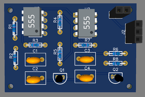
PCB designs:
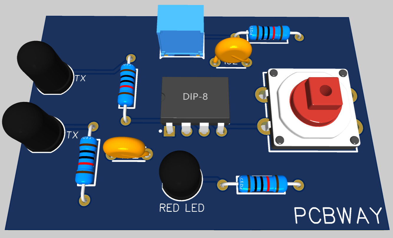
This is the modified PCB layout and if you wan to use the same designs as mine then get them from here.
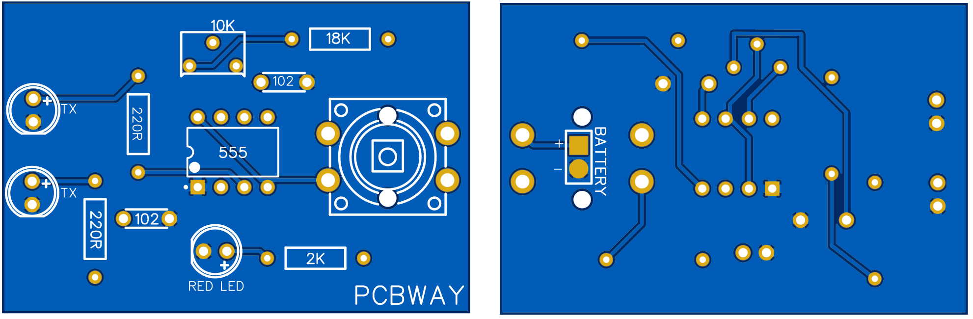
If you sign-up to PCBWAY using this link you will get new user rewards as well as PCB prototype coupons. Battery connector is placed on the bottom layer, a 9volt battery can be connected there.
Working:
As explained above we are not hacking the system but using a physical device to keep the receiver busy. This will help to block the communication with original remote and hence jamming concept implemented.
How to order PCB from PCBWAY.
First, Go to PCBWAY and sign-up using this link. Click on instant quote and choose the designed PCB dimensions, If chosen wrong then corrected by the team of PCBWAY engineers.
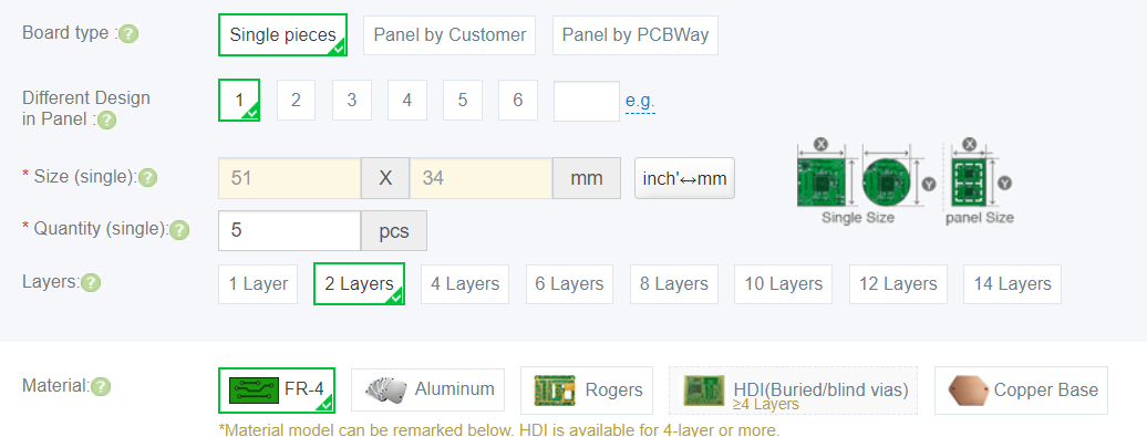
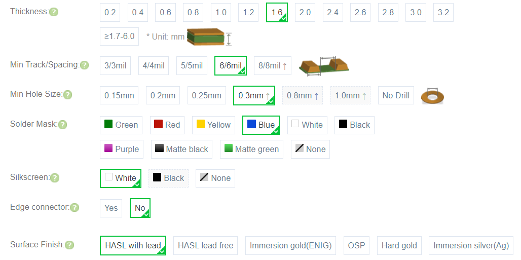
Select the quantity, thickness, color, material and Finishing type.
Calculate the PCB cost and then save it to cart.

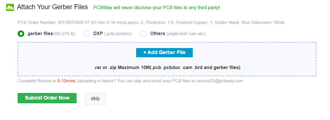
Upload the Gerber file, now engineers will inspect the PCB dimensions, tracks and type and give you the final quote (This will take 5 to 10 minutes).
Checkout and get your PCB just in 7 days at home.
 sandy
sandy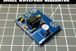
 Sagar 001
 ElectroBoy