Close
0%
0%

Stagmo: Microscope Stage Automator

A low-cost microscope stage automation solution that enables large scale image montages with relative ease.

Similar projects worth following
In microscopy, the field of view is limited and depends on the objective magnification. With growing applications of microscopic imaging and spatial analysis, digitally capturing a large montage of a sample is often required. Automated microscope stages facilitate the production of an accurate montage for a given sample, but entry level cost of these systems ($20,000+) is prohibitive to many researchers. This project provides an alternative options at relatively low cost (~ $100).

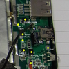
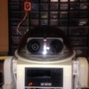
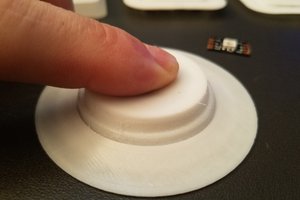
The microscope used in this project is an Olympus Bx40 with a third-party digital camera. Stagmo is secured to an existing microscope stage and stepper motors are utilized to control the existing manual stage control knobs. Stagmo does not require any modification of existing microscope systems, but "straps" on using a clamp system and drive bands. This makes Stagmo ideal for traveling researchers or graduate students who are using other labs' equipment. A simple button interface is used to input the dimensions of the microscopic sample into an Arduino. Stagmo utilizes input dimensions to precisely move the microscope stage every few seconds, and triggers the camera controller on the computer capture an image of the current microscope field and output the image to a specified directory. The path, rows and columns utilized by Stagmo to capture the image are output with the image file into imageJ. The image stitching plug-in by Stephan Preibisch (http://fly.mpi-cbg.de/~preibisch/software.html#Stitching ) is used to assemble the images in the directory into a montage. Since the precise location of each image is specified by Stagmo, this process minimizes the computation load required to produce large montages.

This project was utilized to create cross-sectional montages of over 200 rib samples (@ 10x objective; requiring 15 - 40 fields) and 100 femur samples (@ 10x objective; equiring upwards of 600 fields). Use of this automated system decreased imaging and processing time by roughly 600%.

Results of this study can be found here: https://tspace.library.utoronto.ca/handle/1807/69305

The current version of Stagmo can be greatly enhanced with greater user control (integrated microscope calibration for changing objectives on the fly), improved user interface with a simple lcd to provide the current parameters and estimated time to completion, z-stage control with simple three point calibration system, improved digital camera integration, and an improved chassis/ hardware microscope integration. Interested collaborators should feel free to contact me.

  • 1 × arduino
  • 1 × motorshield
  • 2 × stepper motors
  • 4 × buttons
  • 1 × switch Development Kits, Boards and Systems / Development Kits and Boards

View all 11 components

  • Arduino Code

    Jarred04/21/2015 at 20:13 0 comments

    //parts of this code have been scavenged from code created by: Michael Pilcher
    
    #include <AFMotor.h>
    //manually calibrate your stage to find the values of xmove and y move for each objective you will be using
    int xmove = 12;//[12 (100x)  30 (40x)  dp72] 
    int ymove = 5;//[5  (100x)  13 (40x) dp72]
    int xrpm = 150;
    int yrpm = 150;
    int j = 1; // integer used in scanning the array designating column number
    //2-dimensional array for assigning the buttons and there high and low values
    int Button[9][3] = {{1, 705, 715}, // button 1
                         {2, 735, 745}, // button 1b
                         {3, 830, 840}, // button 2
                         {4, 845, 860}, // button 2b
                         {5, 600, 620}, // button 3
                         {6, 640, 670}, // button 3b
                         {7, 300, 320}, // button 4
                         {8, 445, 460}, // button 4b
                         {9, 260, 265}, // button b
    };
    int analogpin = 0; // analog pin to read the buttons
    int label = 0;  // setting button mode
    int counter = 0; // how many times we have seen new value
    long time = 0;  // the last time the output pin was sampled
    int debounce_count = 50; // number of millis/samples to consider before declaring a debounced input
    int current_state = 0;  // the debounced input value
    int ButtonVal;
    int column=8;
    int row=50;
    int row_count;
    int column_count;
    double movement;
    int pause = 2800;
    int frames=0;
    int count = 0;
    AF_Stepper motor1(100, 1);
    AF_Stepper motor2(100, 2);
    
    void setup()
    {
      Serial.begin(9600);
      motor1.setSpeed(yrpm);  
       motor2.setSpeed(xrpm);  
    }
    
    void loop()
    {
       // If we have gone on to the next millisecond
      if (millis() != time)
      {
        // check analog pin for the button value and save it to ButtonVal
        ButtonVal = analogRead(analogpin);
        if(ButtonVal == current_state && counter >0)
        {
          counter--;
        }
        if(ButtonVal != current_state)
        {
          counter++;
        }
        // If ButtonVal has shown the same value for long enough let's switch it
        if (counter >= debounce_count)
        {
          counter = 0;
          current_state = ButtonVal;
          //Checks which button or button combo has been pressed
          if (ButtonVal > 0)
          {
            ButtonCheck();
          }
        }
        time = millis();
      }
    }
    
    void ButtonCheck()
    {
      // loop for scanning the button array.
      for(int i = 0; i <= 21; i++)
      {
        // checks the ButtonVal against the high and low vales in the array
        if(ButtonVal >= Button[i][j] && ButtonVal <= Button[i][j+1])
        {
          // stores the button number to a variable
          label = Button[i][0];
          Action();      
        }
      }
    }
    
    void Action()
    {
      if(label == 1)
      {
        Serial.println("Button 1");//Y Coordinate down
        motor1.step(xmove, FORWARD, DOUBLE);  
      }
      if(label == 2)
      {
        Serial.println("Column =");
        column++;
        Serial.println(column);
    }
      if(label == 3)
      {
        Serial.println("Button 2"); //Y Coordinate up
        motor1.step(xmove, BACKWARD, DOUBLE);   
    }
      if(label == 4)
      {
        Serial.println("Initiated");
    
       row_count=1;
       movement=1;
       column_count=1;
       frames= row * column;
       while(count<= frames){
          if( movement==1){
           while(column_count <= column){
            motor1.step(xmove, FORWARD, DOUBLE); 
                Serial.println(column_count);
                Serial.println(movement);
            delay(pause);
            count++;
            column_count++;
           }
          }
           if( movement!= 1){
           while(column_count >= 1){
              motor1.step(xmove, BACKWARD, DOUBLE); 
              Serial.println(column_count);
              Serial.println(movement);
              delay(pause);
              count++;
              column_count--;
             }
           }
          if (column_count==column+1){
              if(movement == 1){
              motor2.step(ymove, BACKWARD, DOUBLE); 
                  Serial.println(column_count);
                  Serial.println(movement);
              delay(pause);
              count++;
              column_count = column;
              movement = movement * (-1);
              row_count++;
              
               motor1.step(xmove-2, BACKWARD, DOUBLE); 
              Serial.println(column_count);
              Serial.println(movement);
              delay(pause);
              count++;
              column_count--; 
              }
          }
          if (column_count == 0){
              if(movement ==- 1){
                     motor2.step(ymove, BACKWARD,  DOUBLE); 
                         Serial.println(column_count);
                         Serial.println(movement);
                     delay(pause);
                     count++;
                     column_count =1 ;
                     row_count++;
                     movement=1;
            }
          }
        }
      }
      if(label == 5)
      {
        Serial.println("Button 3");  //x coordinate to the left
        motor2.step(ymove, FORWARD, DOUBLE); 
      }
      if(label == 6)
      {
        Serial.println("Row =");
        row++;
        Serial.println(row);
      }
      if(label == 7)
      {
        Serial.println("Button 4"...
    Read more »

  • Example Montage and Status

    Jarred04/21/2015 at 20:07 0 comments

    Thanks for all the interest, and I apologize for the lack of updates and responses over the last year (my dissertation research got in the way). I neglected to document Stagmo as much as I should have during my graduate research, but I have uploaded an example montage (undecalficied human midshaft femur thick-section – 100~µm thick). The size of this montage was greatly reduced for internet viewing and is made up of 180 individual fields. This demonstrates the ability and weaknesses of Stagmo coupled with an imageJ stitching plugin. The software end is highly sensitive to "blank" fields, so fields with minimal features are more likely to be misaligned (as seen the medullary cavity). Since these fields typically do not have features of interest, this wasnt a big deal for my research and could be fixed in photoediting software using the raw images after stitching for the small number of montages that were problematic.

    Stagmo is currently on hold, but I am happy to revive and update this project with interested individuals. There are a number of improvements that can easily be made. The first edition was significantly hindered by limited tools and materials. Future updates could include a significantly improved UI, computer triggering and interface, and the addition of automated focus control (using a simple plane capturing method). Since stagmo is design to attach to existing stages (which are typically precisely machined and expensive), the general concept should not be restricted to any specific microscope. 3D printed hubs coupled with standard hardware could provide a range of automated options to low budget researchers.

View all 2 project logs

Enjoy this project?

Share

Discussions

ron.nelson wrote 06/04/2016 at 17:56 point

You might want to follow our similar efforts. We've come up with a pretty reliable mounting setup and everything is open source -- anyone interested can e-mail me. http://sybarite.us/category/makingstuff/autoscope/

  Are you sure? yes | no

andyhull wrote 08/29/2014 at 09:51 point
I've been giving this idea some thought, and if I get the chance, I might try a polar co-ordinate approach. By this I mean, make a three servo controlled platform that sits on the existing stage and rotates, shifts and lifts the slide.

I suspect this will take less effort than motorising the existing stage (I am probably wrong in this assumption).

The work flow would be something like... place slide on (clear acrylic?) block controlled by servos, one for rotation (θ), one for horizontal linear movement (h), one for vertical movement (z).

Focus manually on specimen, trigger computer to take a sequence of images by scanning using a polar co-ordinate location algorithm. Lift or lower for change of focal plane with z axis servo...

This would be similar to the method used by this printer.. http://hackaday.com/2014/08/28/thp-semifinalist-theta-printer/

Any thoughts, on the subject, such as ...don't be so daft, it wont work because... would be welcome.

  Are you sure? yes | no

Mike Smith wrote 08/03/2014 at 07:51 point
Hi, I'm based in Kampala, Uganda and am working on automated image analysis (via a microscope and a smart phone). One issue is somehow getting the microscope to focus etc. An MSc student here built some hardware to do this http://aidevmakerere.blogspot.com/2013/03/microscope-autofocus.html . One issue is that we are trying to get the costs down. The clinics have microscopes (but rarely have trained lab-techs), which is why the device might be useful, but the reliability and cost of the autofocus/translation motorisation will probably be prohibitive... (even at $100/clinic). Currently we're thinking of the app telling someone what to do (e.g. turn focus knob clockwise, etc!). This part of the project's not been developed yet, so I'm just looking for ideas.
see the blog for more details about the project: http://aidevmakerere.blogspot.com/search/label/Ocula

  Are you sure? yes | no

Benchoff wrote 08/02/2014 at 17:22 point
Woah. Any chance of putting up some pictures of montages, or some video of it working?

  Are you sure? yes | no

andyhull wrote 07/26/2014 at 20:51 point
Wow... the Olympus Bx40 is rather impressive microscope. You've set the bar pretty high, I doubt if my results will be quite as good, but that isn't going to stop me from trying... I presume as well as moving the stage, you have some form of automatic control of the focus, so you can stack in the z axis as well as stitch in the x and y axis.

  Are you sure? yes | no

andyhull wrote 07/25/2014 at 11:04 point
You've beaten me to it on this project, I have a bunch of microscope stages "rescued" from a local skip... two of which have been resurrected for this exact purpose. I even have the servos and an arduino clone sitting ready to start the project. I'm just missing the magic "infinite amount of spare time" ingredient. best of luck with this... I'll be following along with interest.

  Are you sure? yes | no

naroom wrote 07/11/2014 at 20:59 point
Hey, good to see more science projects in here!

You probably already know about this, but Labrigger is a blog you'd like: http://labrigger.com/blog/

  Are you sure? yes | no

Jarred wrote 07/25/2014 at 06:04 point
Thanks for the link! Looks like something that is right up my alley

  Are you sure? yes | no

Similar Projects

Does this project spark your interest?

Become a member to follow this project and never miss any updates