 ElectroBoy
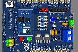
Previously, I made all in one Arduino board this has some extra features of external headers, FTDI and sensor and module mounting. It is very easy to build and a perfect development board for the new hobbyists. You can see the building instructions and components used from here. By the way, RF Arduino is also a popular board nowadays. Which comes with on board NRF24L01 module. So, need to connect external wires to it. Onboard PCB is made so that NRF24l01 is activated by giving CS and CSN signal.

But before going to start this major Project, I choose to go with dedicated NRF24L01 board clone. So that working of circuit is cleared from here. After a successful build we can go with our NRF Arduino. you can see the more features/modes of nRF IC from here.
Components required:

1) NRF24L01
2) Arduino Nano/Uno
3) 22pf capacitors
4) 16mhz crystal oscillator
5) 100nF, 1.5pf, 10nf, 1pf ceramic capacitors
6) 8nh, 5nh and 3nh inductor’s
All of these parts can be collected from the old nRF module and the component description /circuit diagram is given below.
Circuit diagram:
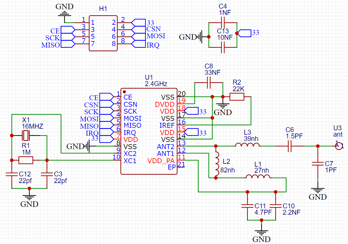
This module can be interfaced with Arduino by SPI connection. MOSI, MISO and SCK pin is connected to D11, D12 and D13 respectively. This module works on 3.3volt filtered power supply. Get the Arduino shield of this module from here for testing purpose. 2 more connections are their knowns as CS and CSN which is used to select the chipset.

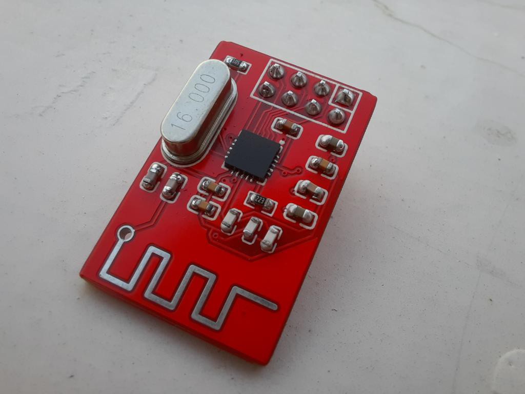
All the circuit components can be gathered from any old nRF module. No need to worry about the alignment because I made the proper replica of the original PCB. So that we can place the components in the same manner as these are on original on.
PCB files:

I modified the PCB layouts so that components placement seems similar to original NRF module. If you want to use same file to make your OWN nrf24l01 module then get it from here. NRF24L01 chip is a 24 pin QFN SMD package, which is not easy to solder. If you want to reduce the soldering/assembling efforts then JLCPCB SMT assembly service is the best solution starting from just $8.
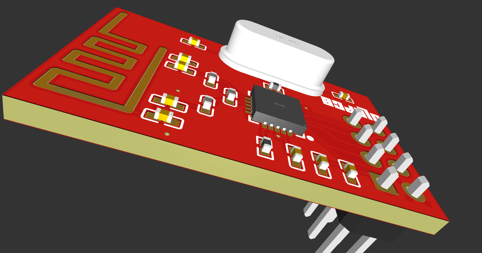
I choose 1.6mm, Red color, FR4 material and HASL finished PCB for my project. Sign-up now to JLCPCB to get the free new user coupons of worth $54.
Assembly:
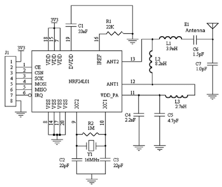
All the components info is given here. you can utilize this data to do more practical embedded project with nRF.

It is not easy to solder 20 pin QFN package in this small form factor board. You can also try Smt assembly services offered by JLCPCB. you can match the data in above given circuit diagram and place the components accordingly. That's why
Working:

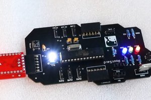
I paired this module to Arduino using a PCB shield, all the connections info is given in a secondary blog with instructions to the schematics and circuit. The modules can be directly paired with Arduino using the shield which has onboard 3.3volt regulator and filtering capacitors.
I made a setup in the previous article, you can see that from here. which includes the project code and Arduino connections. There are two different setup one for the transmitter and other one for the receiver. With this we can test same pinout, different modules with different specs. And I am really very thankful to JLCPCB to sponsor this project. You should give a visit to know about services.
 Mrinnovative
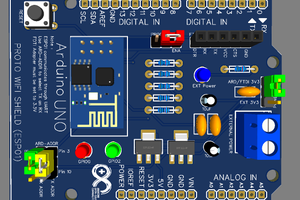
 Jithin Sanal
 Silícios Lab