 David Matthew Mooney
-
1Cuts required
The plywood product I used was 1/2x2x4 G1S, $37 ea before tax in Ontario in summer of 2022. For the project infrastructure, four 1" x 4" x 8' knotty pine planks would be price competitive and less work to waterproof, but less convenient to transport. They may have a stiffness advantage, being thicker, and be less prone to stripped threads.
One of the plywood sheets is for the reflector and the other is to be cut lengthwise into eight 4-foot strips 3” wide to make the base and universal joint assembly (UJ). Each sheet weighs 5 kg (11 lb).
From the strips, cut the following 24 lengths, all in inches. The UJ hypotenuse is chamfered on one long edge on one end.
Dowel lengths: azimuth, 30"; elevation, 34".
Length, in
Part no.
Function
Strip number (shows suggested tiling)
3
7
Spacer for diagonal base brace
1
6
18
Spacer for elevation motor paddle
1
6
17
Elevation motor paddle
1
6
17
Azimuth motor paddle
3
11.5
14
UJ side
3
12
3
Horizontal crosspiece
2
12
15
UJ side
3
16.3
16
UJ hypotenuse
3
11.3
10
Left vertical brace
4
19
9
Diagonal base brace
4
24
6
Cross base element
5
24
4
Cross base element vertical
5
24
8
Side base element
6
24
5
Side base element vertical
6
14.9
11
Right vertical brace
4
30
1
Left vertical strut
2
30
2
Right vertical strut
1
48
19
Hinge strip for attaching reflector
7
2.625
20
Azimuth spacer
scrap
48
21
Reflector
Sheet 1
24
22
L strut reinforcer
8
24
23
R strut reinforcer
8
6
24
UJ gusset plate
scrap
3
28
Rear caster spacer
Scrap, width = 2.75”
Other wooden parts:
18
25
Base brace reinforcer
1.5 x 1.5” x 24” hdwd
12
26
Body diag. upper
1.5 x .75” pine scrap
10.25
27
Body diag. lower
“
-
2Detailing for fastener placement
Excuse the amateurish Powerpoint CAD.
- The big disks are carriage bolts and a foot.
- Small rectangles are furniture brackets.
- The UJ triangle will use a wooden block in each corner for fastening.
- The vertical braces will both use furniture brackets with their angles widened as necessary in a drill press vise.
- The right brace will use a connection block at the lower end instead of furniture braces, because I wanted to use up the fourth block, which are made in pairs.
- The heads of the carriage bolts face the reflector.
- The crosspiece is in front of the verticals when you stand behind the reflector.
- The UJ hinges go on the front of the crosspiece and outside the triangle of the UJ, at the bottom of a side of the triangle.
- The base brace and spacer are not shown in the napkin sketch.
![]()
![]()
![]()
![]()
![]()
-
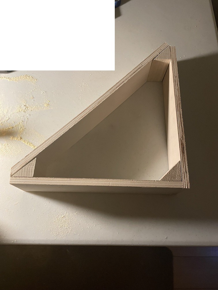
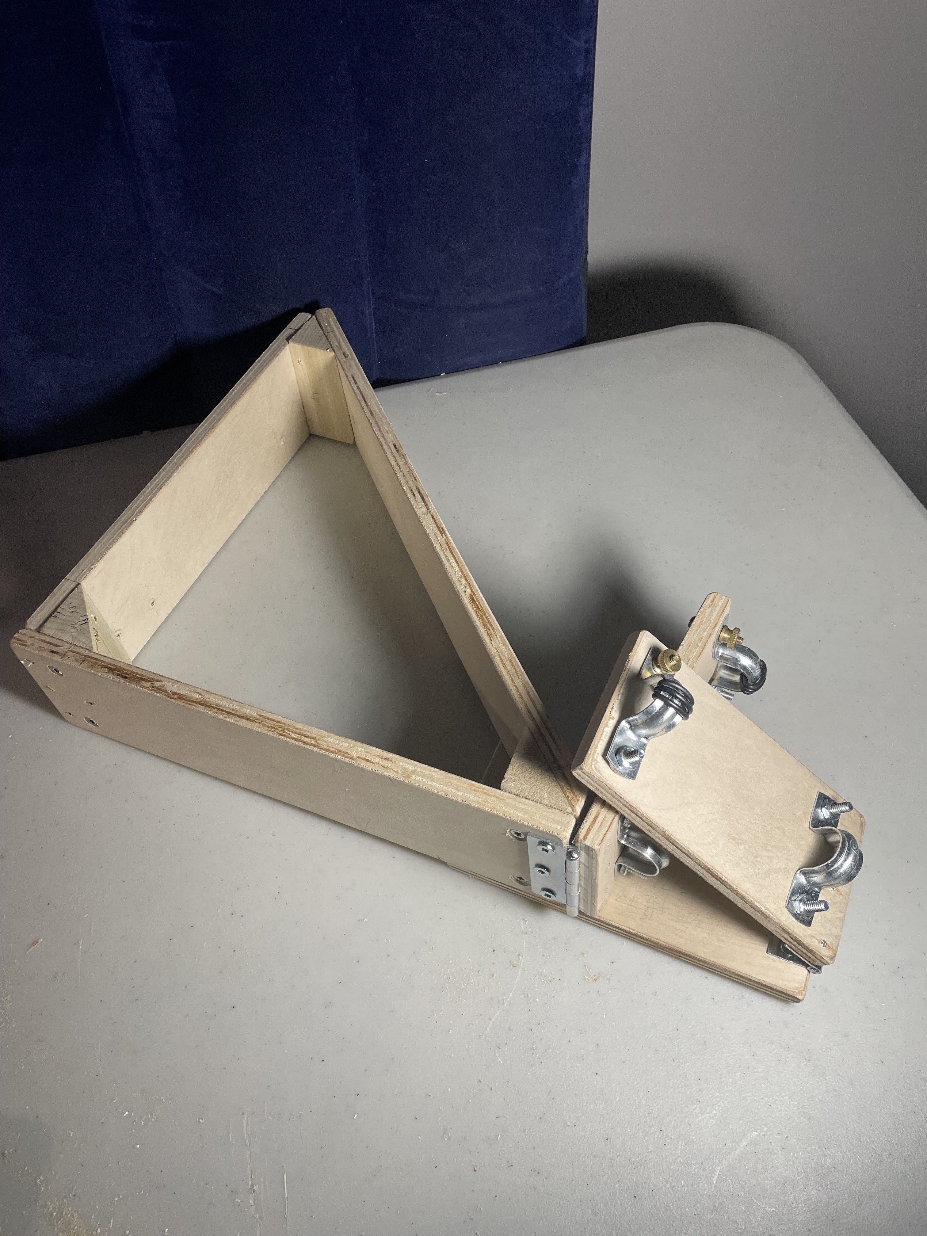
3Miter-box cuts (mostly 90 degrees but precise)
Frame the UJ as shown except that the chamfer is on the wrong end.
![]() Complete the cuts and keep an eye on the humidity. I gather that for best results, you condition all lumber in the room where it will be cut (done) and cut everything the same day. (Or at least at the same humidity?) Right after cutting, I sanded all edges and corners, (outside and while wearing gloves) because I was getting tired of infected splinters. I put on a P100 respirator halfway through sanding. I finished by brushing off the sandings with a new shoeshine brush. Now everything I cut feels like a wooden kid's toy.
Complete the cuts and keep an eye on the humidity. I gather that for best results, you condition all lumber in the room where it will be cut (done) and cut everything the same day. (Or at least at the same humidity?) Right after cutting, I sanded all edges and corners, (outside and while wearing gloves) because I was getting tired of infected splinters. I put on a P100 respirator halfway through sanding. I finished by brushing off the sandings with a new shoeshine brush. Now everything I cut feels like a wooden kid's toy.![]()
-
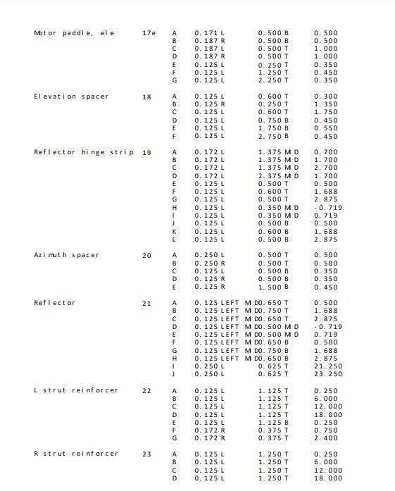
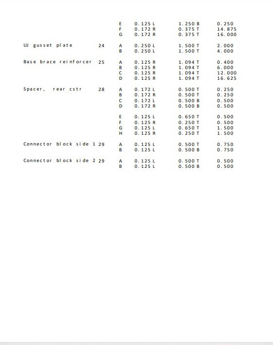
4Hole placements
There were so many holes to specify that I put them in a spreadsheet, which follows. The part numbers are illustrated in a new drawing in the gallery.
Notes:
- Part 16, chamfer is on the bottom rear edge.
- Part 10: the angles of the two upper furniture brackets are to be widened to 153 degrees in a drill press vise and the angles of the lower brackets closed up to 63 degrees. (To drive the lowest screws, come in with a long screwdriver from the side.)
- Part 11: The brackets at the top are to be widened to 135 degrees.
- File the last 1/16” off woodscrews so they do not draw blood if left protruding from the far side of the plywood.
- Part 22 must be further cut before marking the holes for drilling. Cut a long rectangular notch out of the upper right corner, 1.25" wide by 14.75" long. I used a hand-held jigsaw.
Key to table:
- Dimensions are in inches.
- Top-bottom is the longest dimension and the Y-coordinate by convention.
- T = top; B = bottom; L = left; R = right; ref = reference ("measuring from")
- H = horizontal; V = vertical; UJ = universal joint (the triangle); MID = midpoint of long dimension, positive is up; LEFT MID = left of midpoint of short dimension. An X dimension of 0.001 means that the hole is to be drilled perpendicularly into the edge and centered with respect to the thickness dimension.
- All 0.25"-dia. holes are for carriage bolts.
- All 0.125"-dia holes are pilot holes for flat-head woodscrews of length 0.625" (metal to wood), 1.0" (wood to wood, countersink, outer hole is 0.172" dia), or 1.25" (high-stress wood to wood, countersink, outer hole is 0.172" dia.).
- All 0.313"-dia holes are for tee-nuts for the feet.
Center-to-center hole separations in the hardware that dictated pilot hole placement (if more than 2 holes, this is between the outside holes):
- Casters: 1.000" horizontally and 2.100" vertically.
- Conduit clamps: 2.000"
- 3" hinges, 1.750" wide, between universal joint and base: 2.375"
- 2 1/2" hinges, 1.000" wide, to motor paddles: 2.000"
- 3" hinge, 1.125" wide, to reflector hinge strip, top: 2.375”
- 2" hinge, 0.875" wide, to reflector hinge strip, middle: 1.438"
- 3" hinge, 1.125" wide, to reflector hinge strip, bottom: 2.375"
Holes in the furniture brackets are effectively 0.625" from the bend.
Last revision (checked for errors internally and against the prototype): Jan. 03, 2023.
Man! You just can't proofread enough! If you find an error in the table, please tell me in a comment, and I apologize to anyone who has been inconvenienced by my mistakes.
![]()
![]()
![]()
![]()
![]()
-
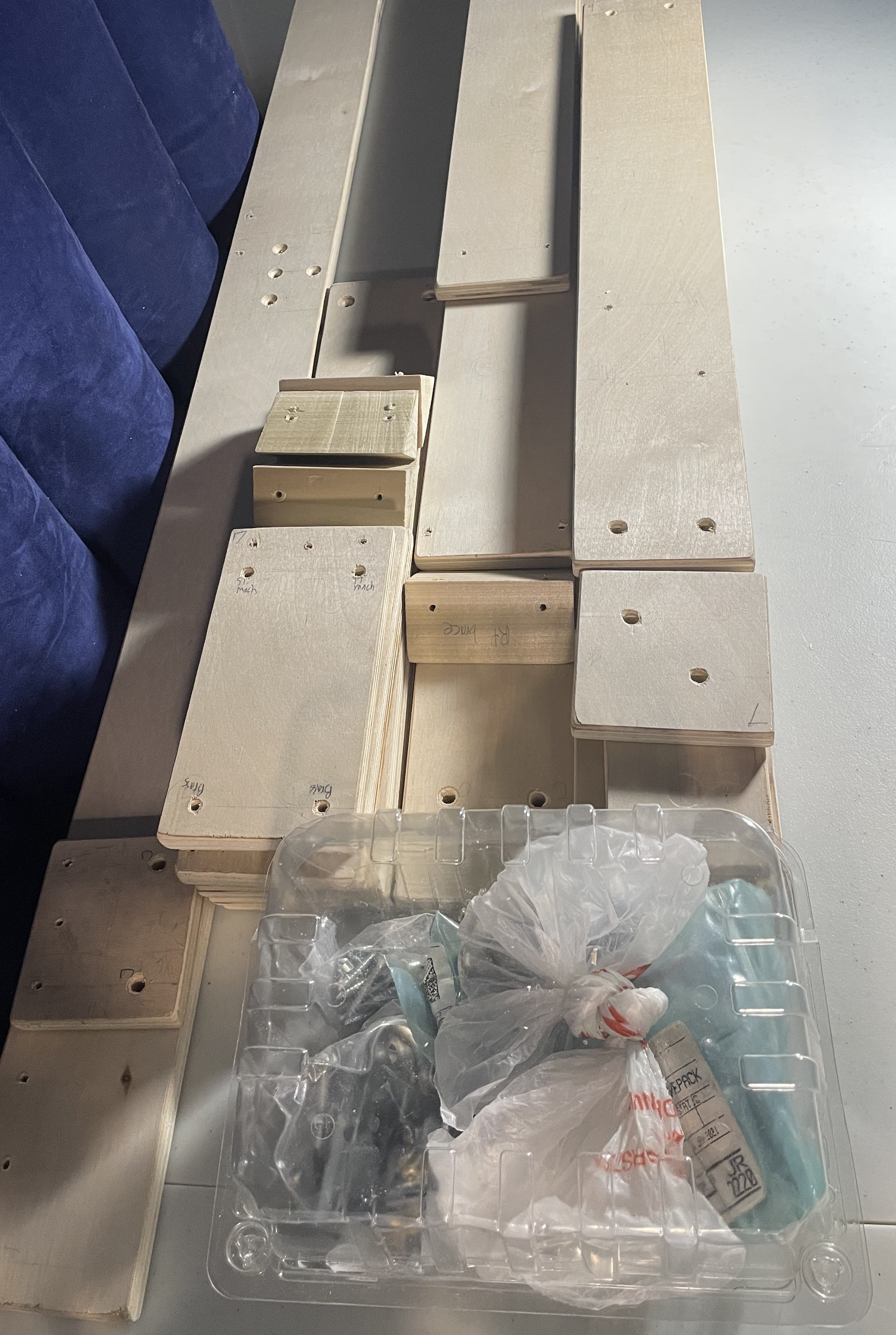
5Drill the holes and waterproof
Here is the sanded, drilled project. The holes were ragged as drilled, (Belated insight: this can be prevented by putting a block of wood under the hole you are drilling) so I cleaned them up by slightly countersinking them on both sides with a half-inch twist drill, manually.
![]()
To waterproof:
- Lightly moisten and dry the wood before sanding.
- The cheap grades of plywood that I buy have interior voids that only show on cut edges, and these must be sealed with wood filler (push it in firmly) and sanded before waterproofing.
- Sand the edges with 60-100 grit to plug many pores with sawdust, thereby helping to seal the end grain.
- Lightly sand the faces before waterproofing.
- On the edges, really glug on the sealant using a brush.
I injected waterproofing fluid (Thompson's WaterSeal) into all connector holes after putting masking tape on one side, so that they got a really good soak. I used the syringe shown below (has many uses), which I made by hot gluing a medicine dropper to a tube taken from a lubricant spray can (1.25" long x 2 mm OD), with roughening and cleaning of the two pieces before joining. The Thompson’s does not quite clean up in detergent and water but leaves a sticky film that can be removed with Varsol.
High-wear areas like the dowels and motor plates were waterproofed with two coats of epoxy wood hardener (PC-Petrifier) rather than the Thompson's and lightly sanded with 220 grit when cured.

The top dropper is for filling the bottom dropper. The droppers are shown with the jig used for gluing, which is a souped-up drill press vise. -
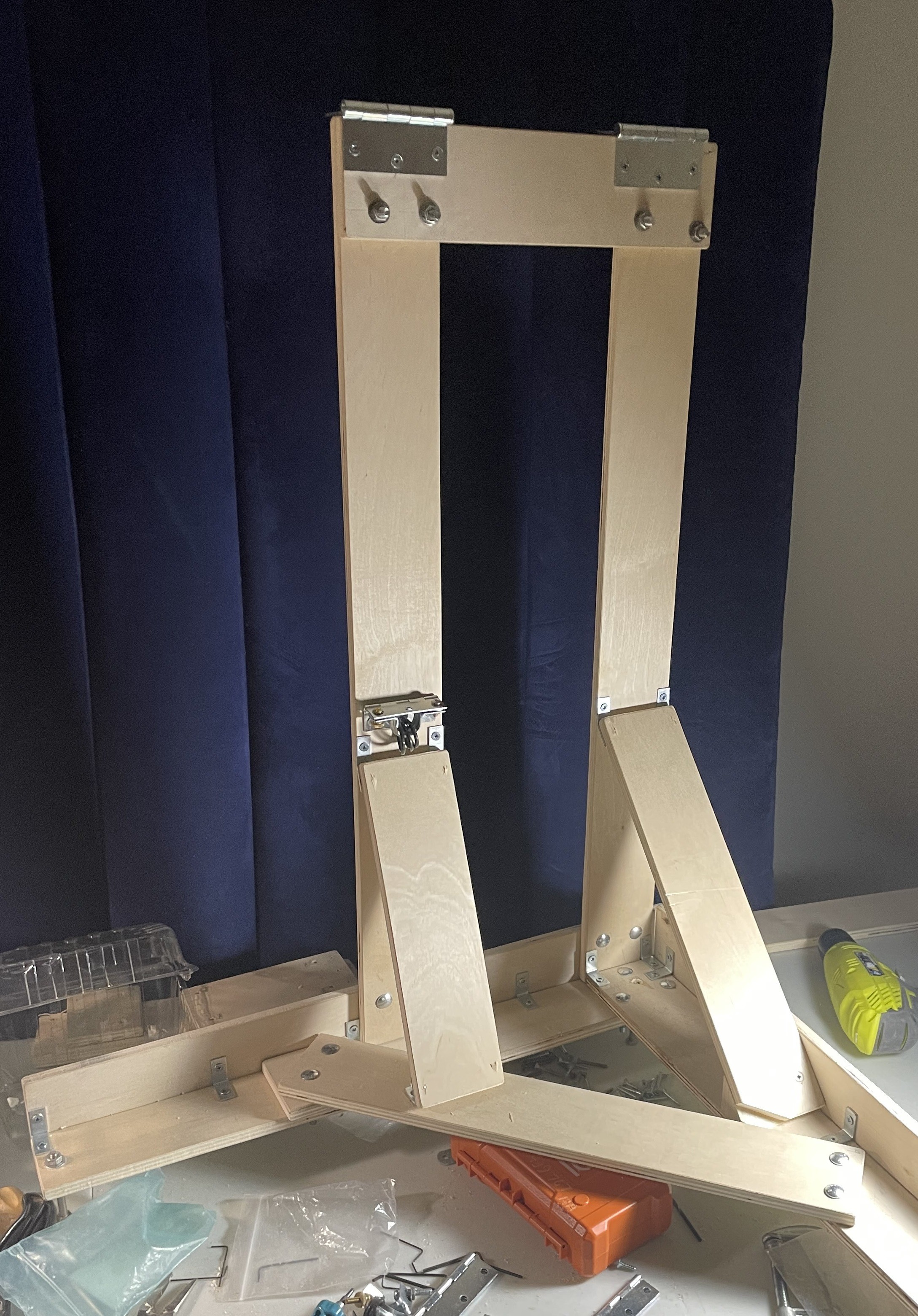
6Put it together.
First impressions: the vertical struts are not stiff enough, the device badly needs ballasting, the two paddles have a small clash in some configurations, and the pushrods have a friction issue.
The reflector is reflective on both sides and sealed around the edges with duct tape.
Here is the assembly sequence I used. The bottom of the right brace (part 11) had to be sawn a touch to make enough room for part 9.
![]()
![]()
![]()
![]()
Use a rafter square to ensure right angles when assembling. ![]()
-
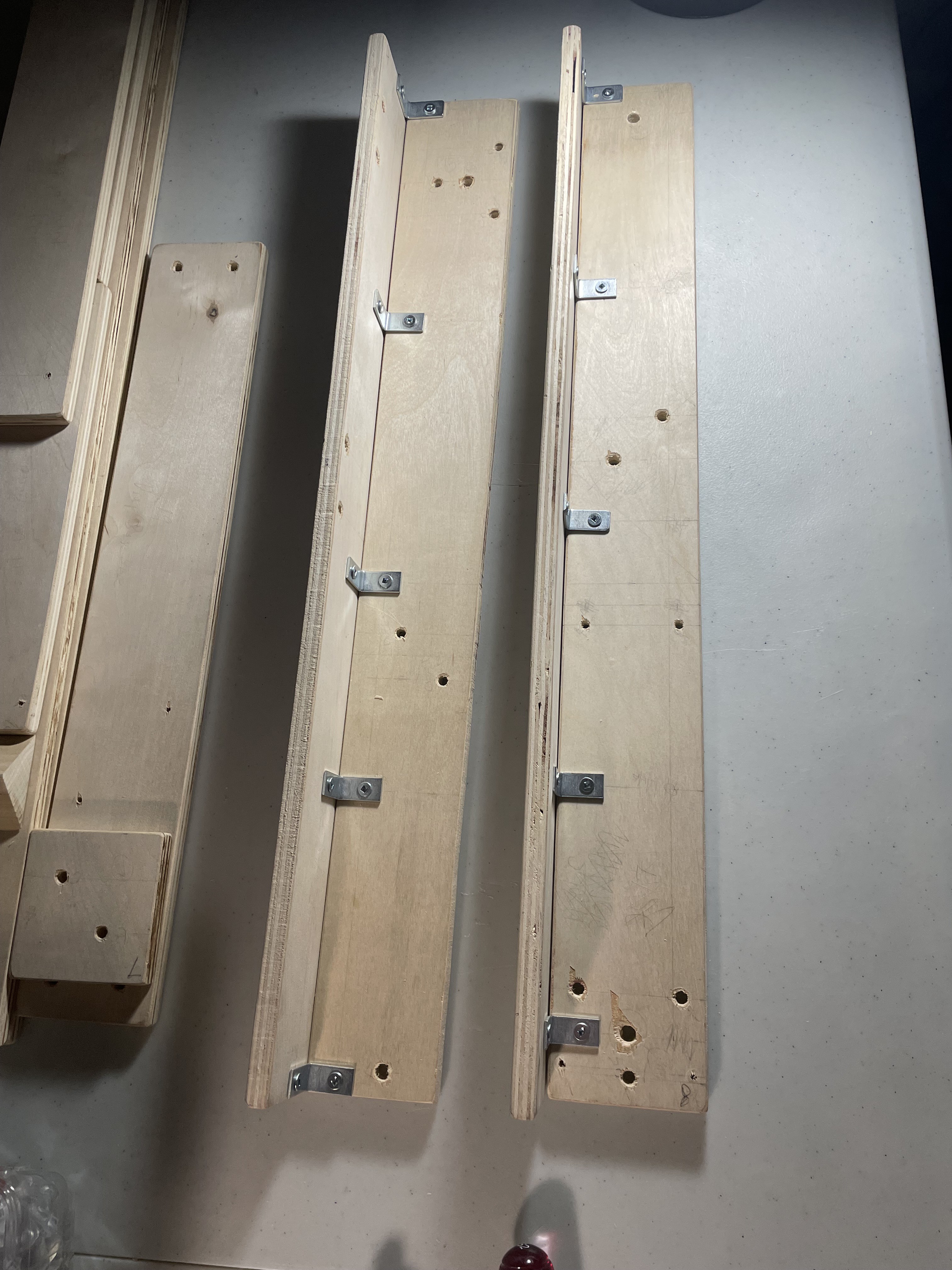
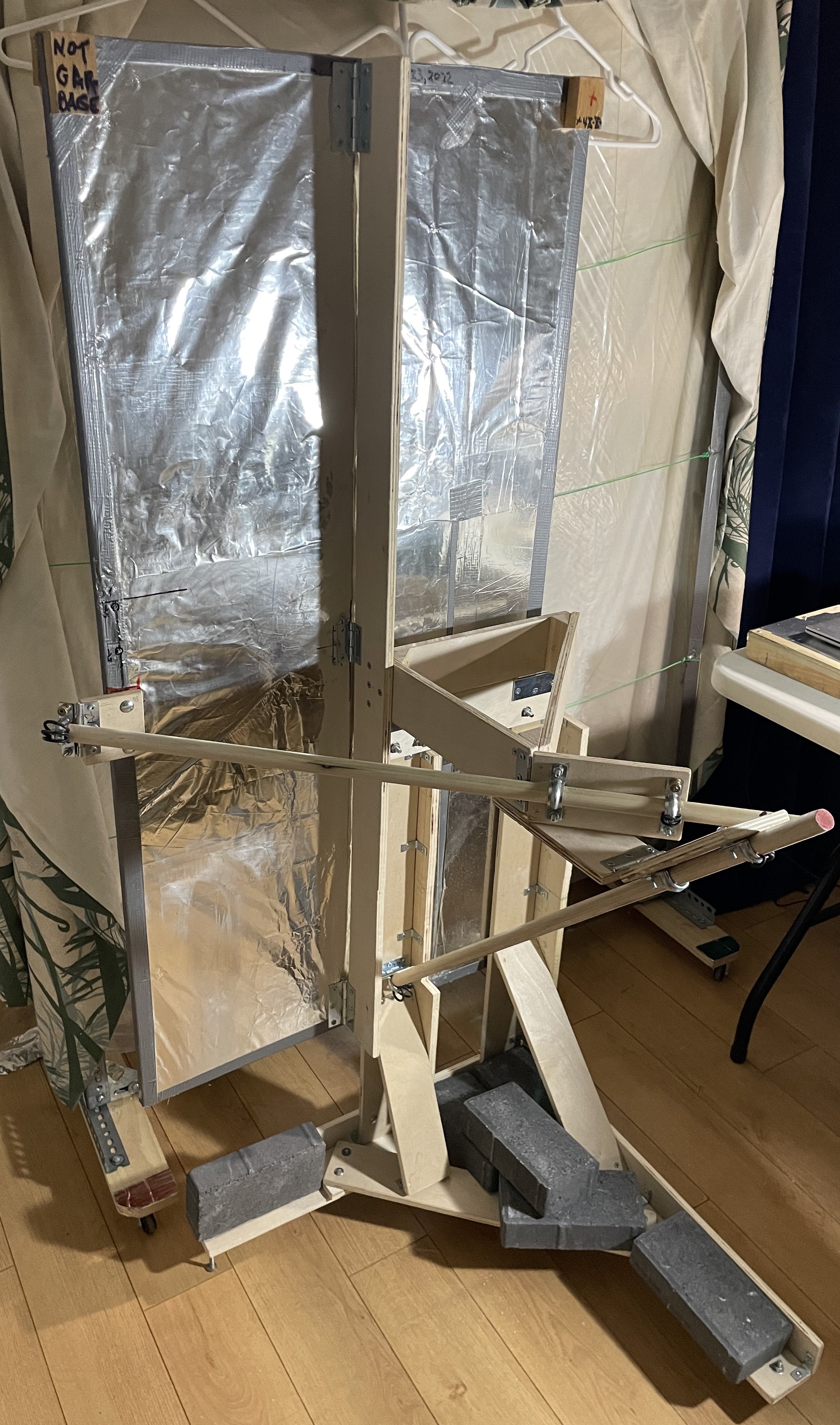
7First-round bug fixes
The eighth strip was used up reenforcing the verticals as shown. The top 15" of the left reinforcer had to be cut down to a width of 1.75" to make room for the UJ when it was completely folded down. The slip-fit guides didn't slip until I put washers under them. All conduit clamps on the paddles have been chamfered on the inside with a tapered Dremel grinding tool to reduce binding. Six pavers were added to the base.
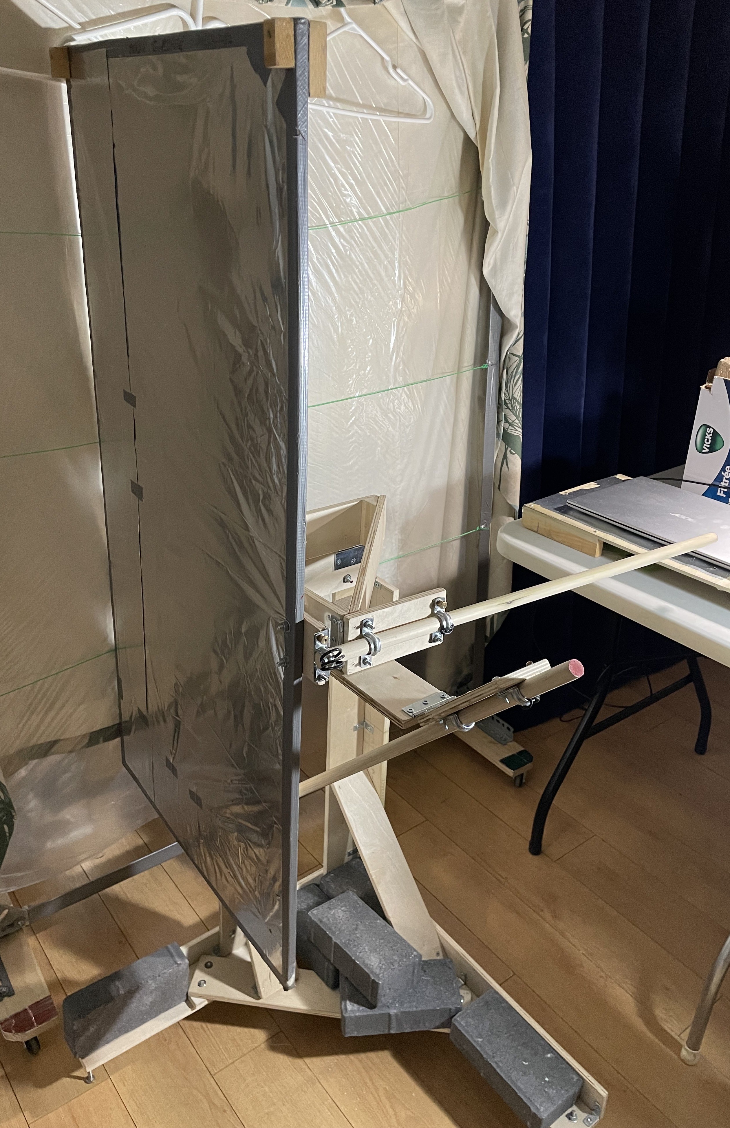
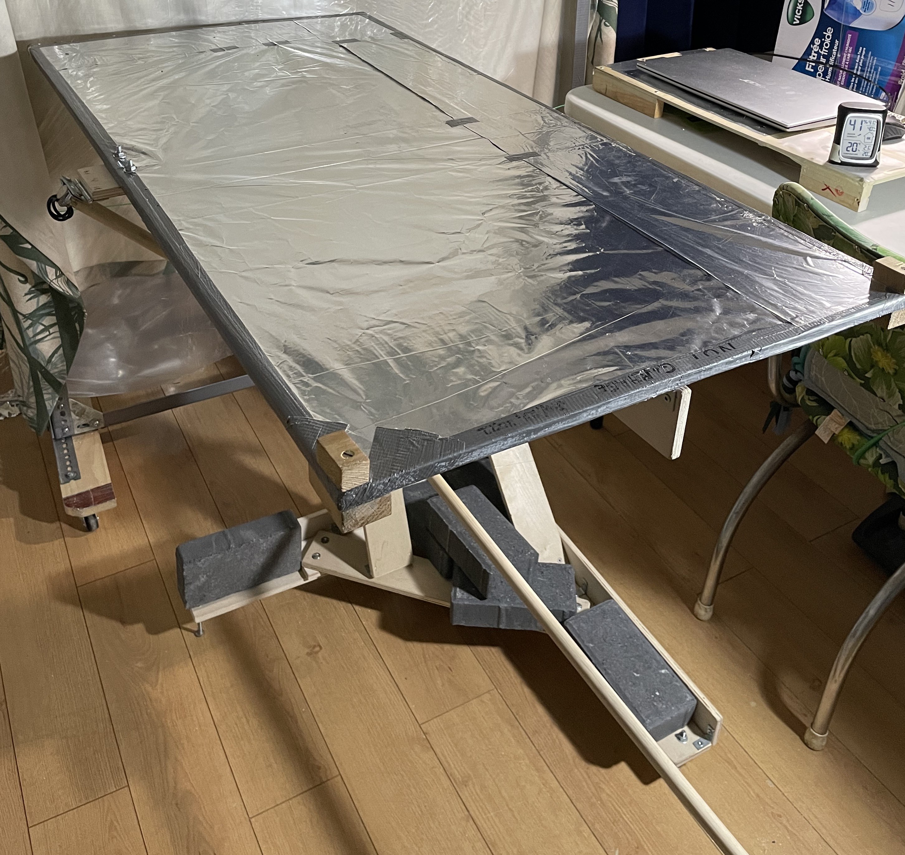
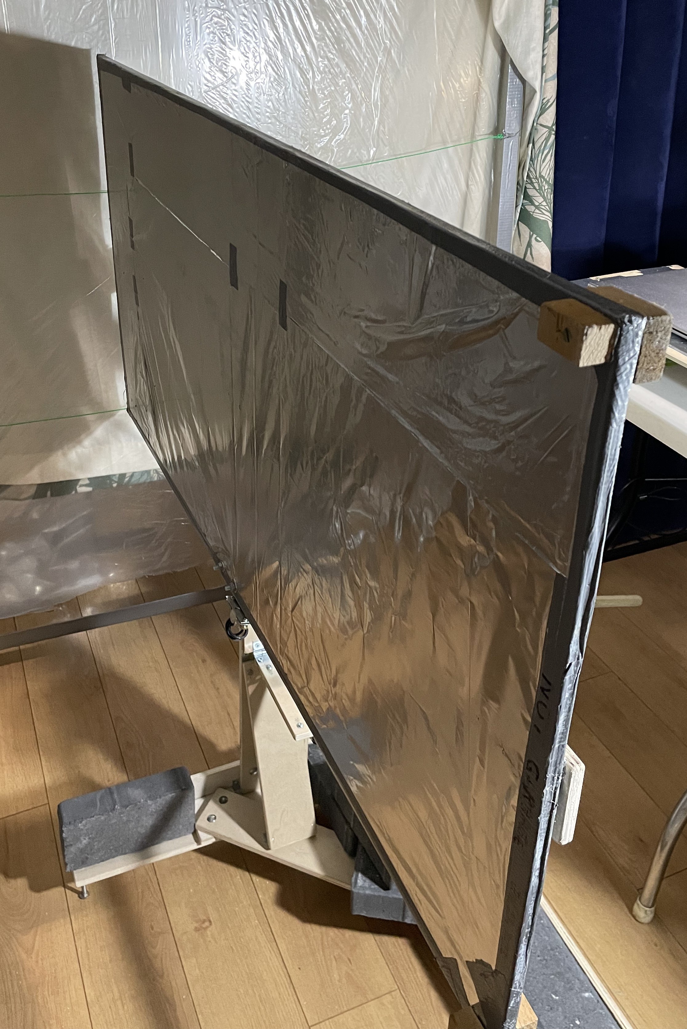
Shown is the improved project being put through its paces.
![]()
![]()
![]()
![]()
-
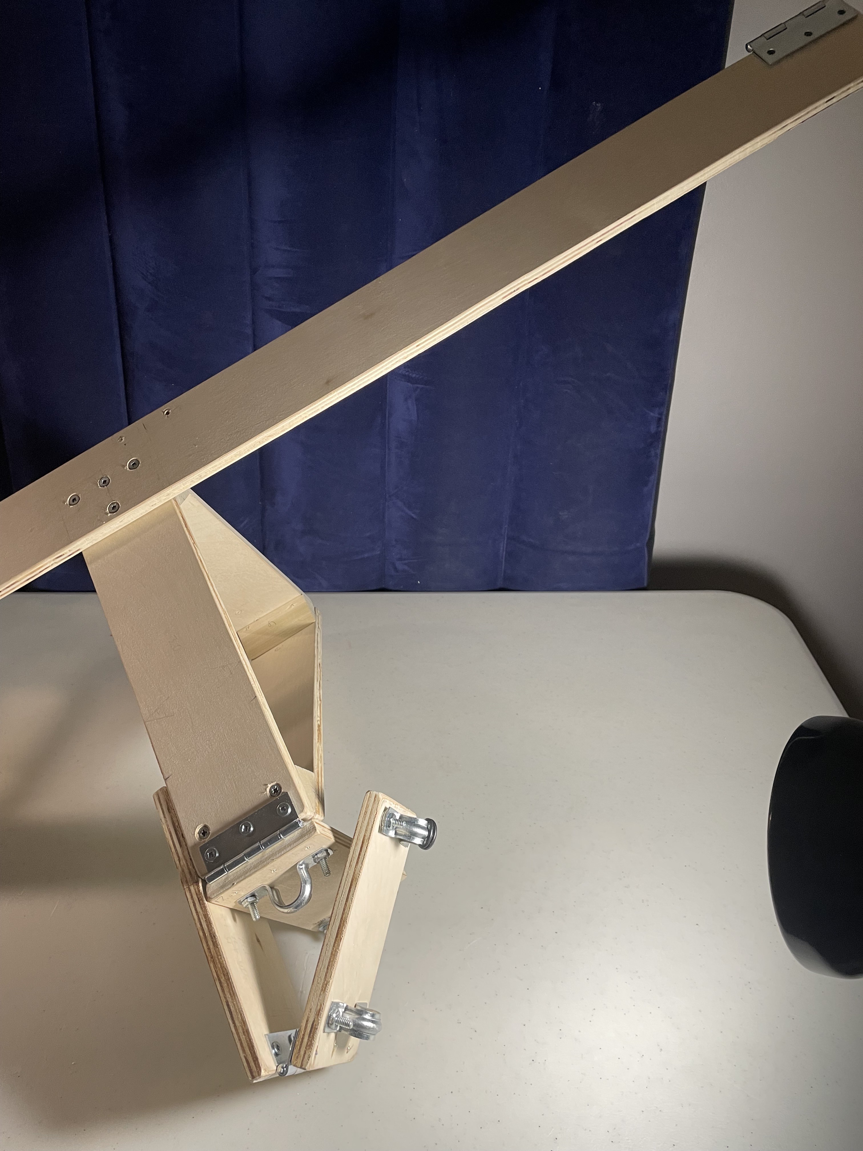
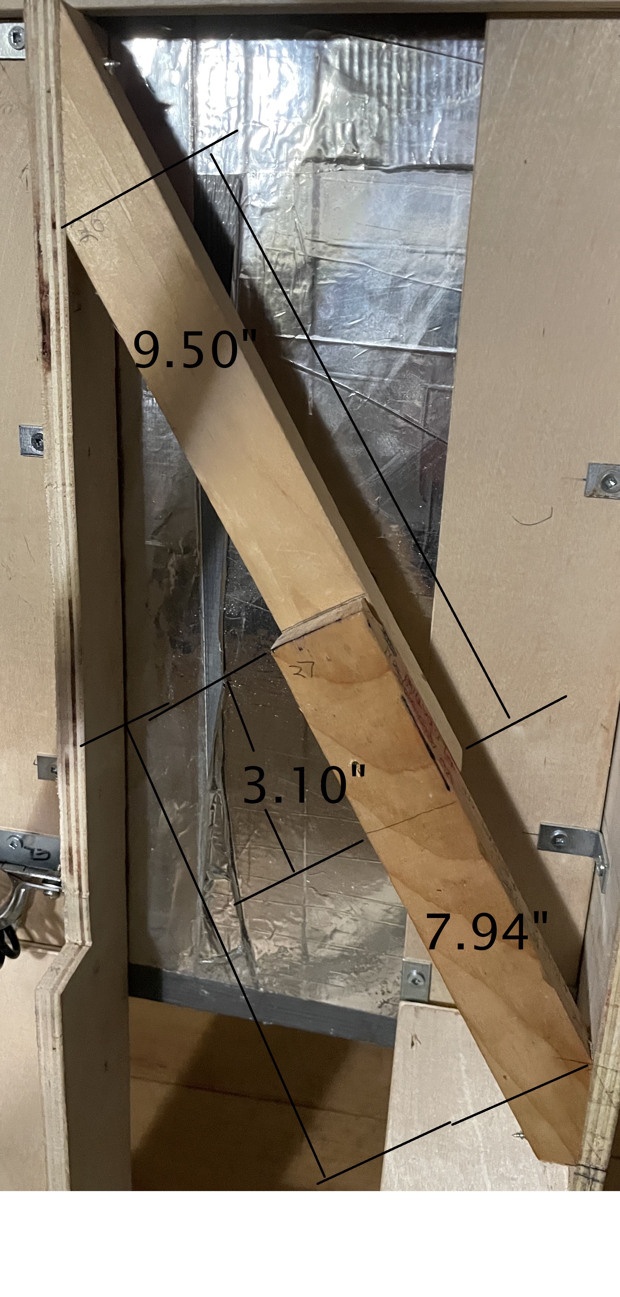
8Second-round bug fixes
Required:
- Add a body-diagonal brace to resist torques.
- Strengthen the hinge-strip joint to the UJ.
The body-diagonal brace has a 31-degree mitered cut at top and bottom.
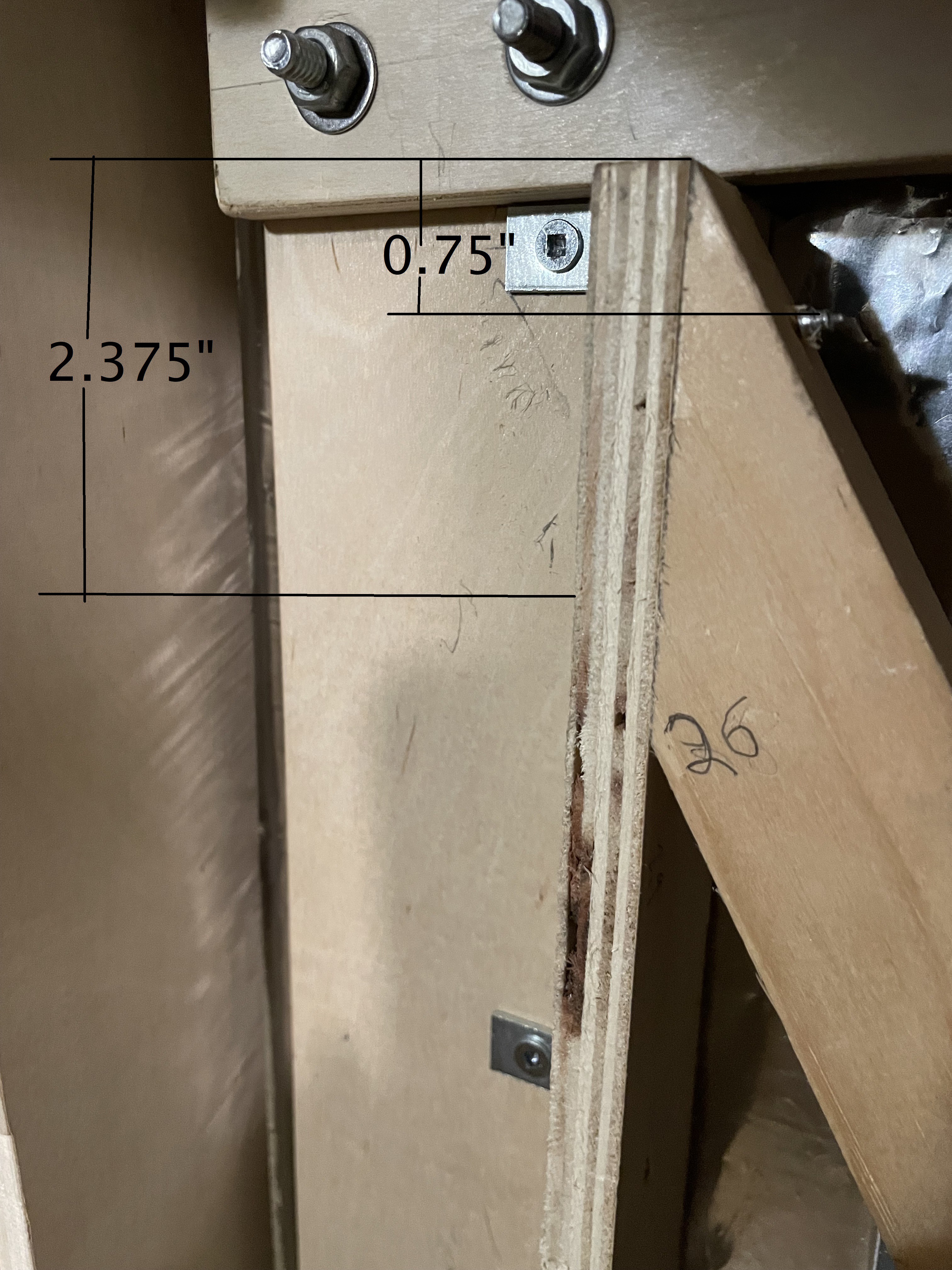
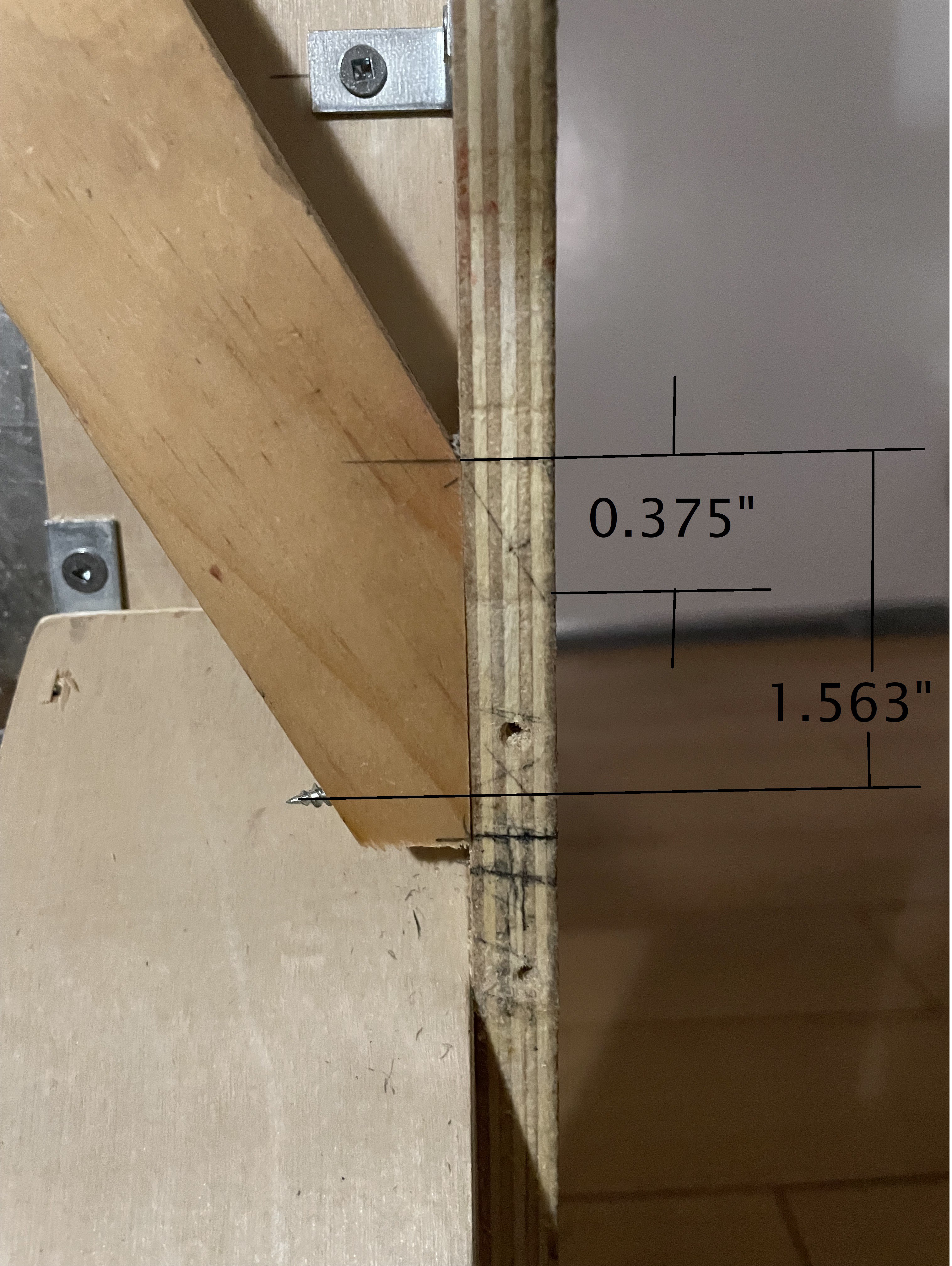
Shown below is a detail of the body-diagonal brace, annotated with dimensions. All pilot holes are centered with respect to the depth dimension of the pine sticks.
![]()
The upper and lower parts overlap to provide some span in the depth dimension and are fastened with two 1.25" flat-head woodscrews, which cannot be seen in this shot. The bottom had to be cut back a touch to make it fit.
![]()
![]()
-
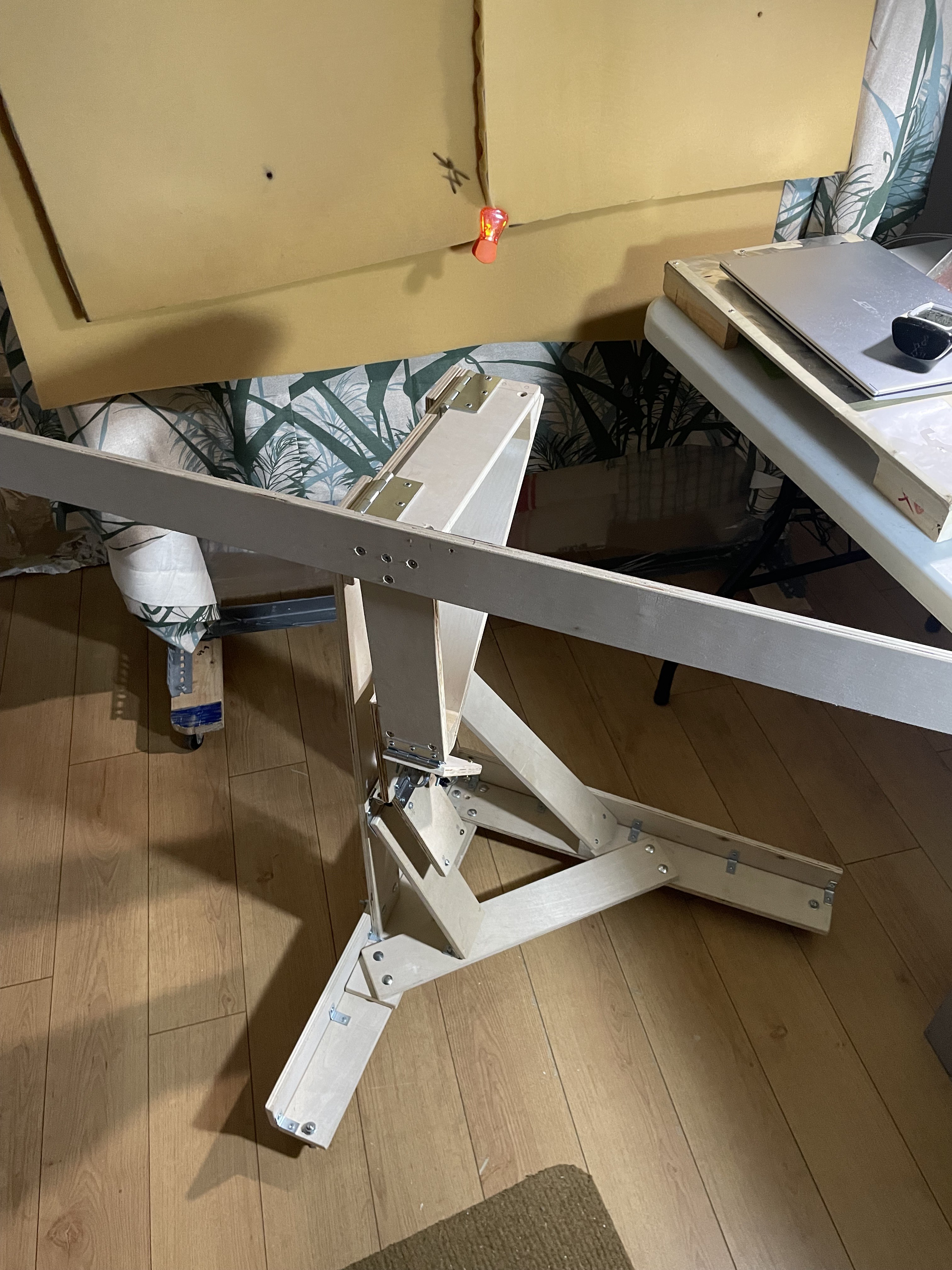
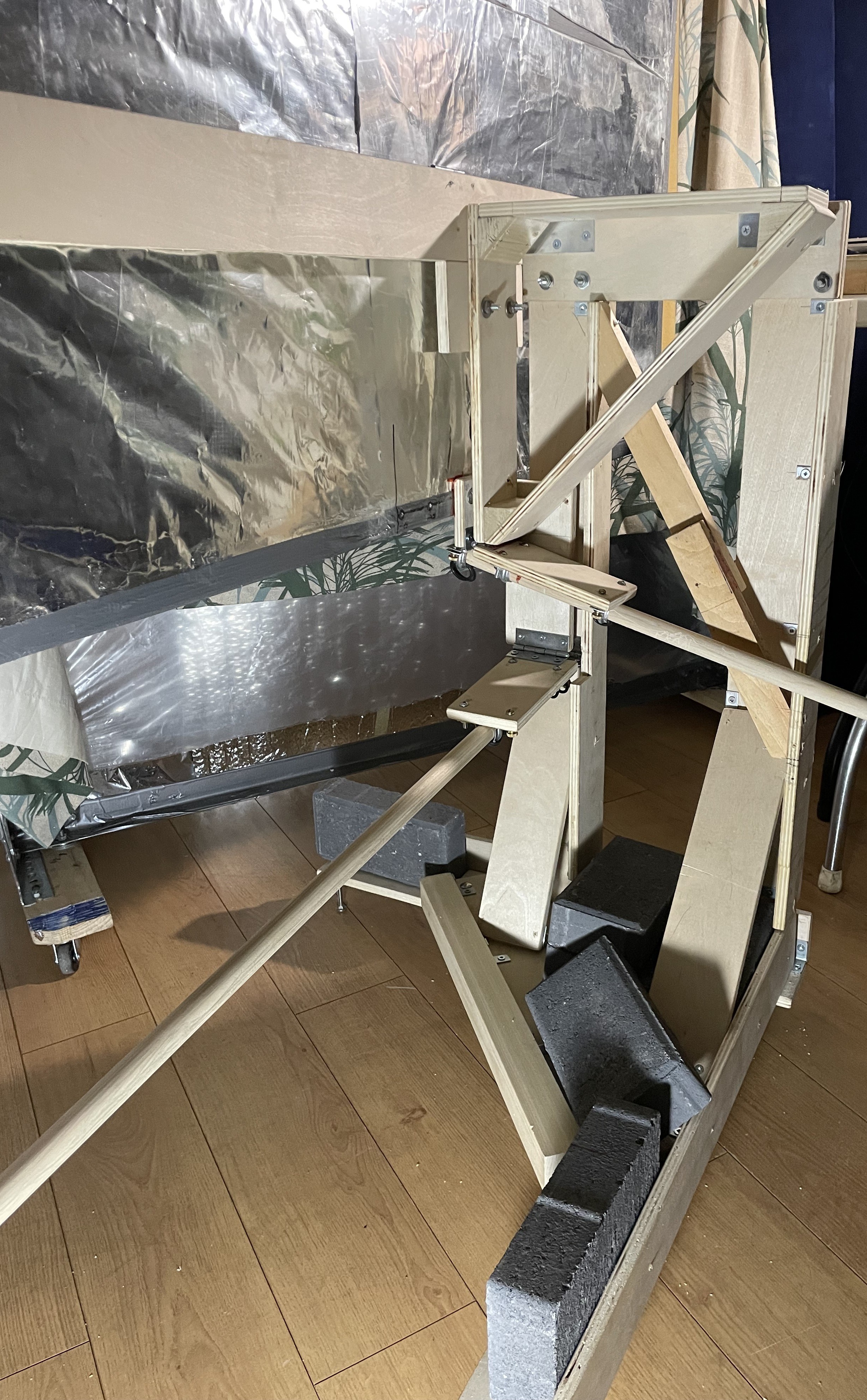
9Third-round bug fixes
A reinforcing bar was added to the base to increase the overall stiffness of the build. The reinforcing bar was the remainder of the 1.5 x 1.5 x 24” stick from which I made the connection blocks. All of the second plywood sheet has been used up except for one 3" x 3" scrap.
The amount of wobble has now been reduced to acceptable levels and I am declaring this design done.
Final component weights after conveniences added:
plywood, 22 lb (77%); solid wood, 1.8 lb (6%); hardware, 4.8 lb (17%); total, 28.6 lb.
![]()
-
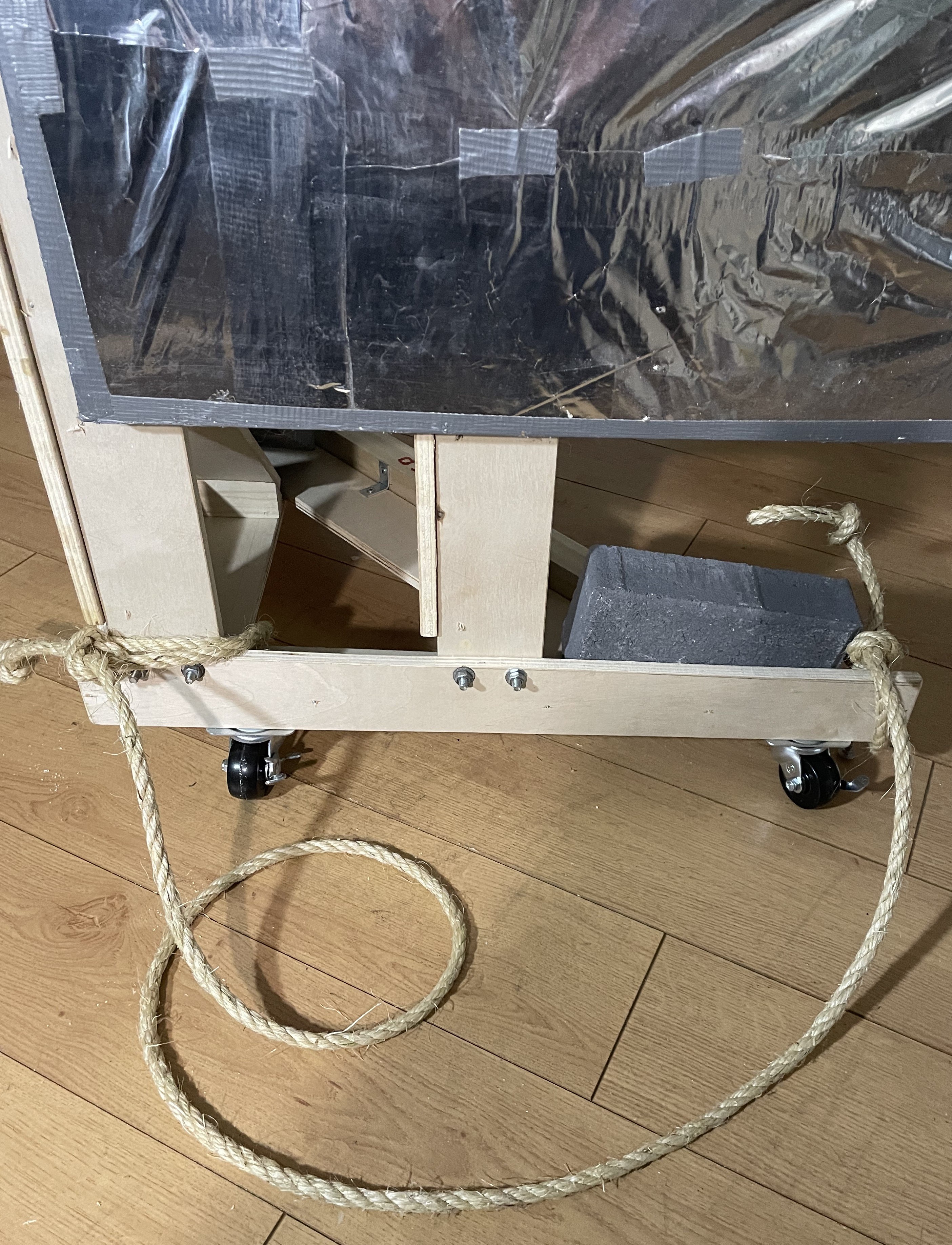
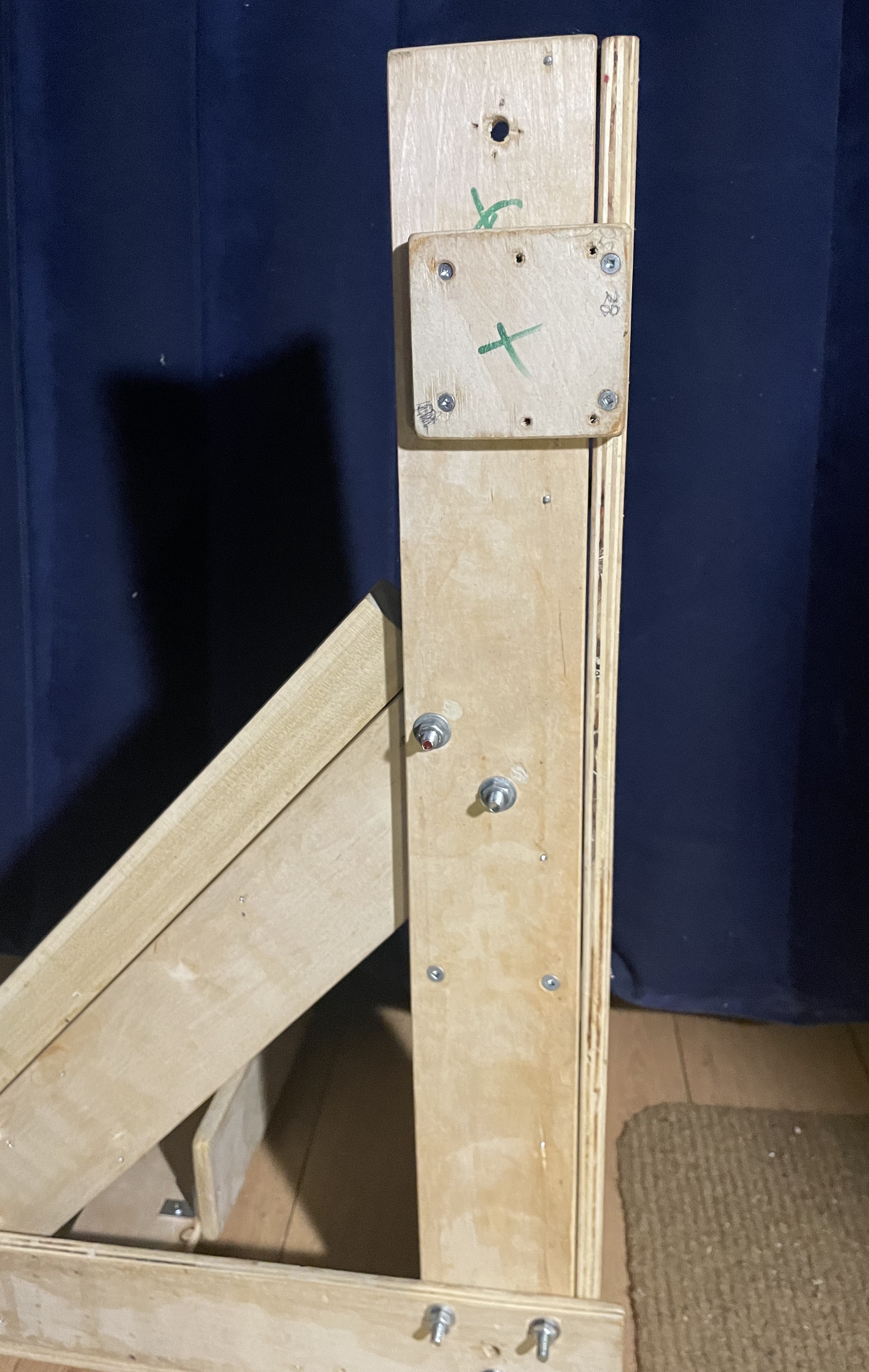
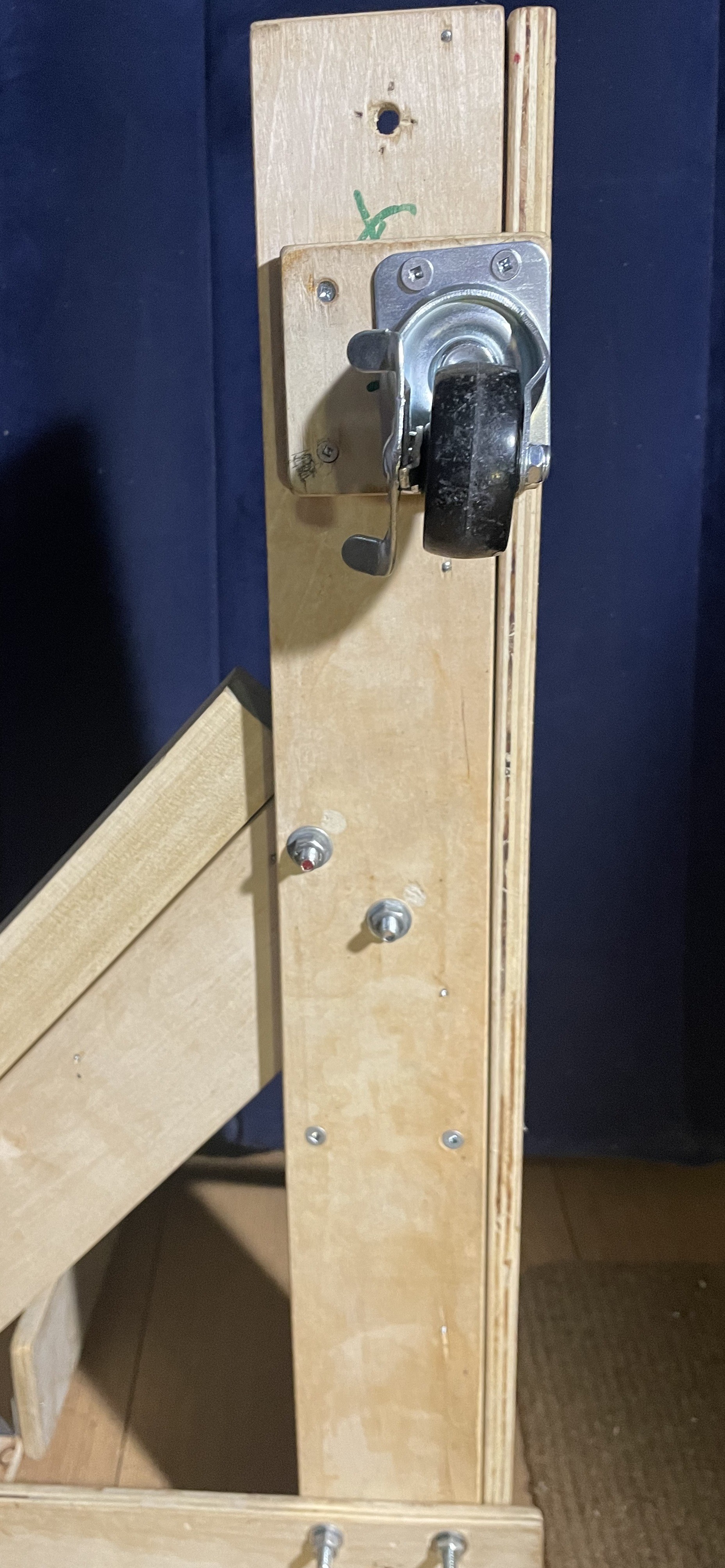
10Those all-important conveniences
I added three 2"-dia swivel locking casters, one near each fixed foot. This required one plywood spacer under the rear caster, thereby almost completely using up the second plywood sheet. A rope handle was then added as well as two round-head woodscrews (not shown) to prevent the right end from slipping. These additions were made because I anticipate a lot of trial and error in deciding on the final location and orientation of the heliostat.
![]()
![]()
![]()
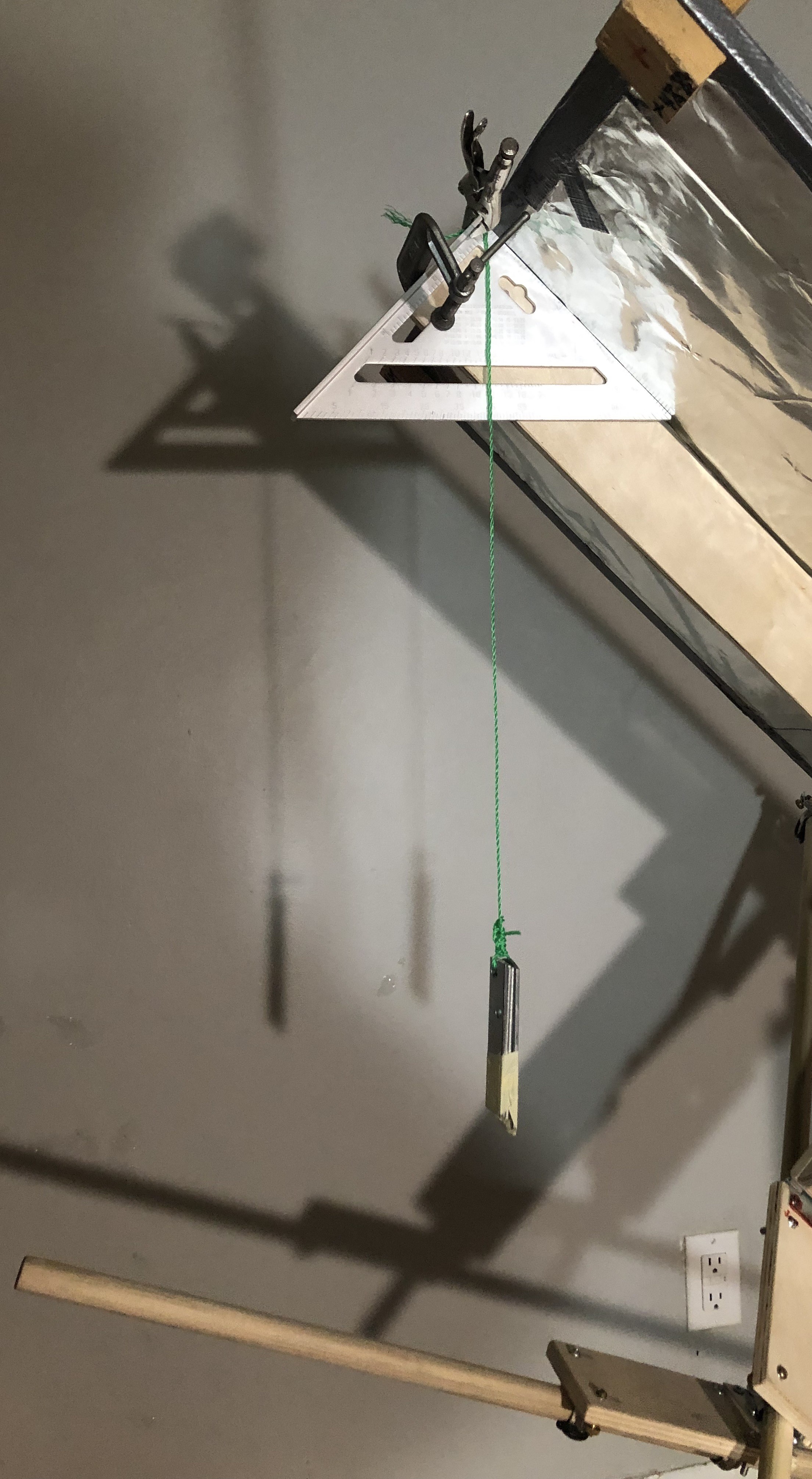
This is my arrangement for marking the elevation pushrod to show angles. Before beginning, I made sure the base was level.
![]()
The Learner's Heliostat
A heliostat to provide experience in making greater use of sunlight for heating, lighting, and drying, thus reducing my carbon footprint.
 Complete the cuts and keep an eye on the humidity. I gather that for best results, you condition all lumber in the room where it will be cut (done) and cut everything the same day. (Or at least at the same humidity?) Right after cutting, I sanded all edges and corners, (outside and while wearing gloves) because I was getting tired of infected splinters. I put on a P100 respirator halfway through sanding. I finished by brushing off the sandings with a new shoeshine brush. Now everything I cut feels like a wooden kid's toy.
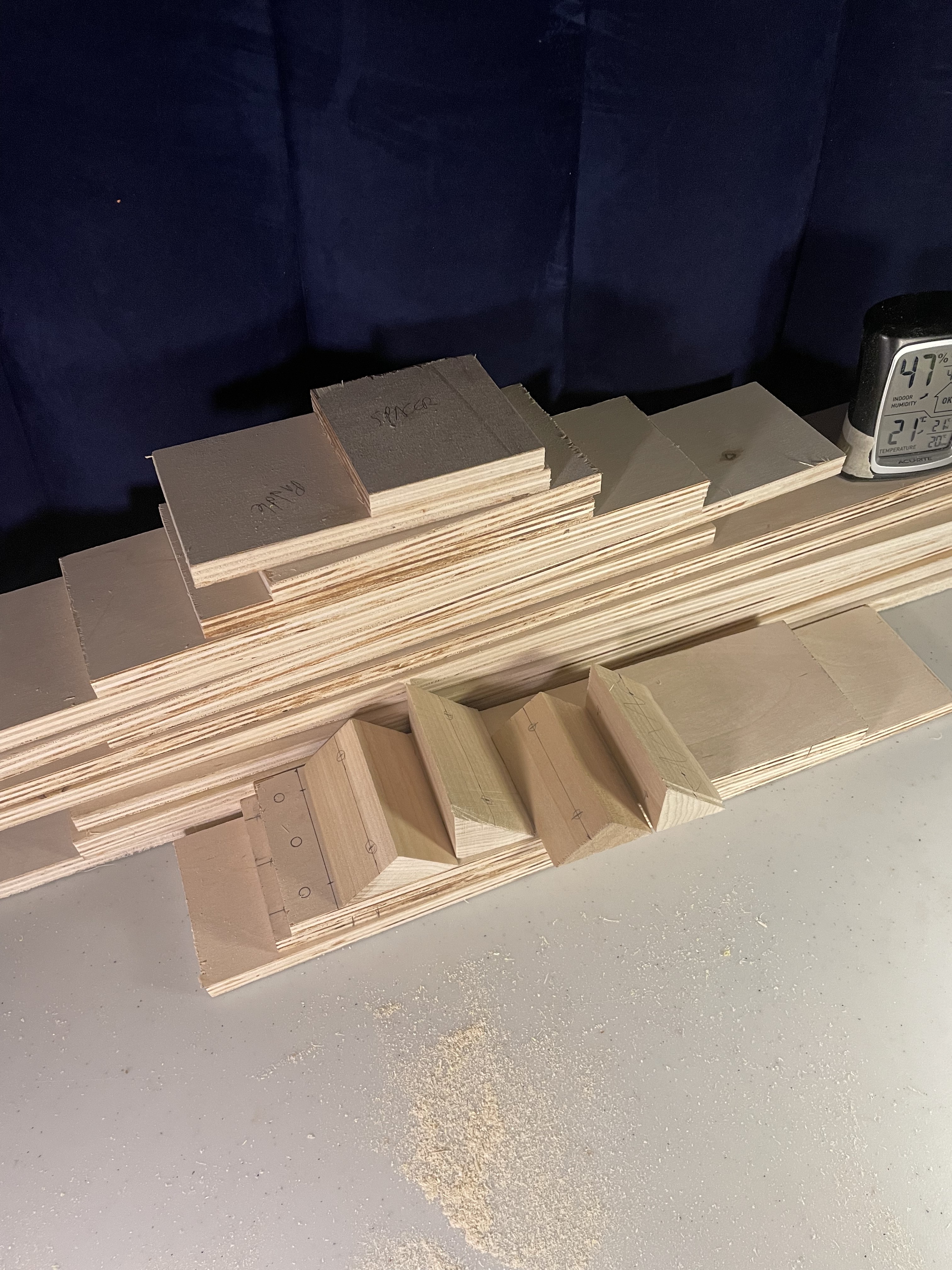


Discussions
Become a Hackaday.io Member
Create an account to leave a comment. Already have an account? Log In.