A picture is worth a thousand words.
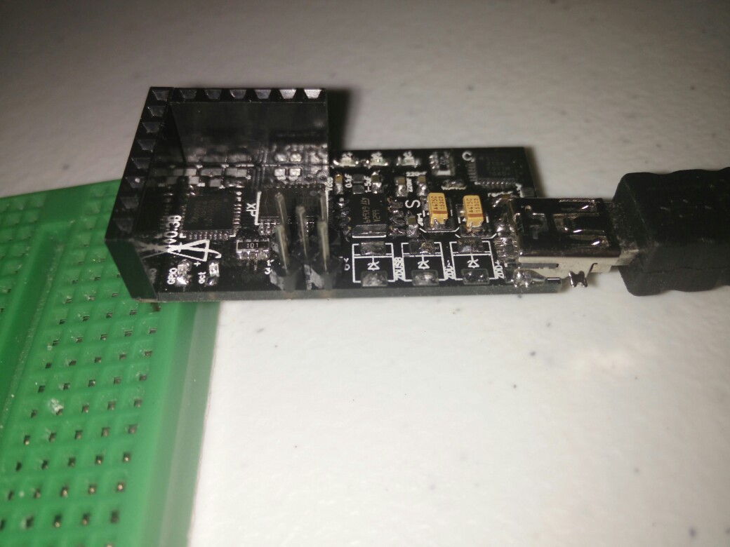
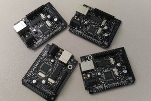
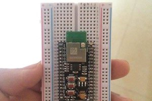
So a video is like, a lot. These videos show the simultaneous view from the board (and my phone), and my PC. A hacky looking board can be seen in the corner there, which can miraculously switch power on and off on any pin, as well as routing power between pins, monitoring pins with an ADC, and a few more neat features to come. If you'd like to see more, leave a comment / email describing your ideal uses.
I am working on a variant with over 128 IO pins, one integrated into the breadboard itself, one with resistance as low as 0.5 Ohm and one with voltages exceeding 12v. I can't get everything done at once, however, so feedback is appreciated!
TLDR Overview
All boards are USB compatible and have onboard 3.3v supply (some also have 12v).
All boards will include a UI and API for tinkerers.
Some boards will have resistance under 1 Ohm.
Some boards will handle in excess of 500mA.
Some boards will handle in excess of 12v.
Some boards will support in over 128 IO pins.
Design
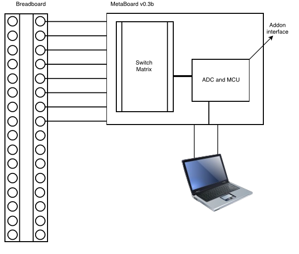
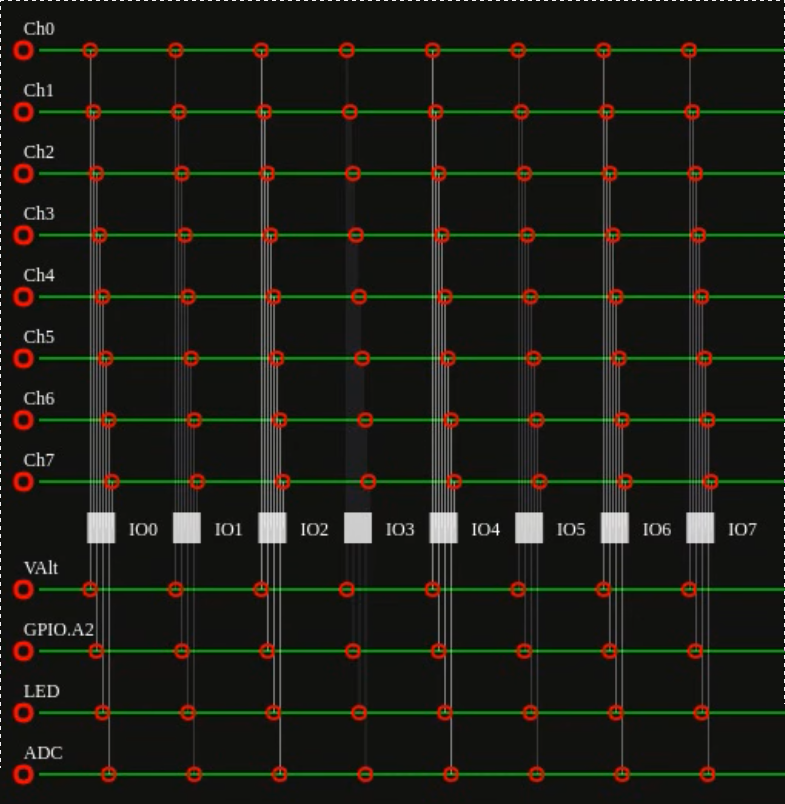
Programmable – our software interface interacts with hardware to cater to the caprice of every programmer. It replaces wires with a programmable switch array. The user interface interacts with the switch array so you can connect channels (effectively "wires") to IO pins without touching your design. It also interacts with the onboard ADC so that you can manipulate your designwith the click of a button and monitor signals in real time, all on the same little chip.
Connectivity – USB and browser based UI! Compatible and portable!
Modular – Easily develop and attach custom features to the board.
Compatible with Arduino
Applications
Replace wires
1. Connect the controller board to your breadboard and PC.
2. Connect channels to IO pins in the user interface.
The user interface will interact with the hardware and implement your configuration on a breadboard via a programmable switch matrix, thereby replacing wires.
Monitor signals
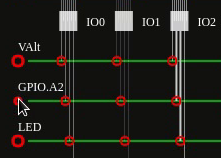
1. Connect the GPIO channel to the ADC channel on the same IO pin.
2. Set the ADC channel on.
Then you can analyze the signal.
Build custom shields
This feature is still in development.
Specs
We are working on specs right now for the current iteration. Expect specs of the standard features by next week.
Block Diagram
The Team
Hi everyone! We are a new startup called Freesearch. We are a team of makers based in Australia. We want to hack your breadboard for the better.
R&D
 Freesearch



 arnie.omallao
 AVR
AVR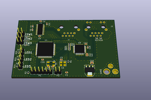
 Anuj Deshpande
Interesting project, so this is a digitally controlled array of switches for controlling what sections of the breadboard are connected ? In the chat you asked for feedback perhaps a better explaination? If you need PCB and hardware feedback though I can provide that as well. Keep at i!