 Rue Mohr
I should start with credits, this is a circuit derived from the article by Roman Black
https://www.romanblack.com/shift1.htm
I have improved the timing and made it so that you have control over all 8 bits.
My original work was done in 2019 with a tiny13.
The system breaks the waveform into 4 symbols:
- low pulse of "5us" - shift in a 1
- low pulse of "36us" - shift in a 0
- high pulse of "10us" - NOP
- high pulse of "32us" - Latch shift register to output register.
When not in use the control line is left high.
Here is my circuit:
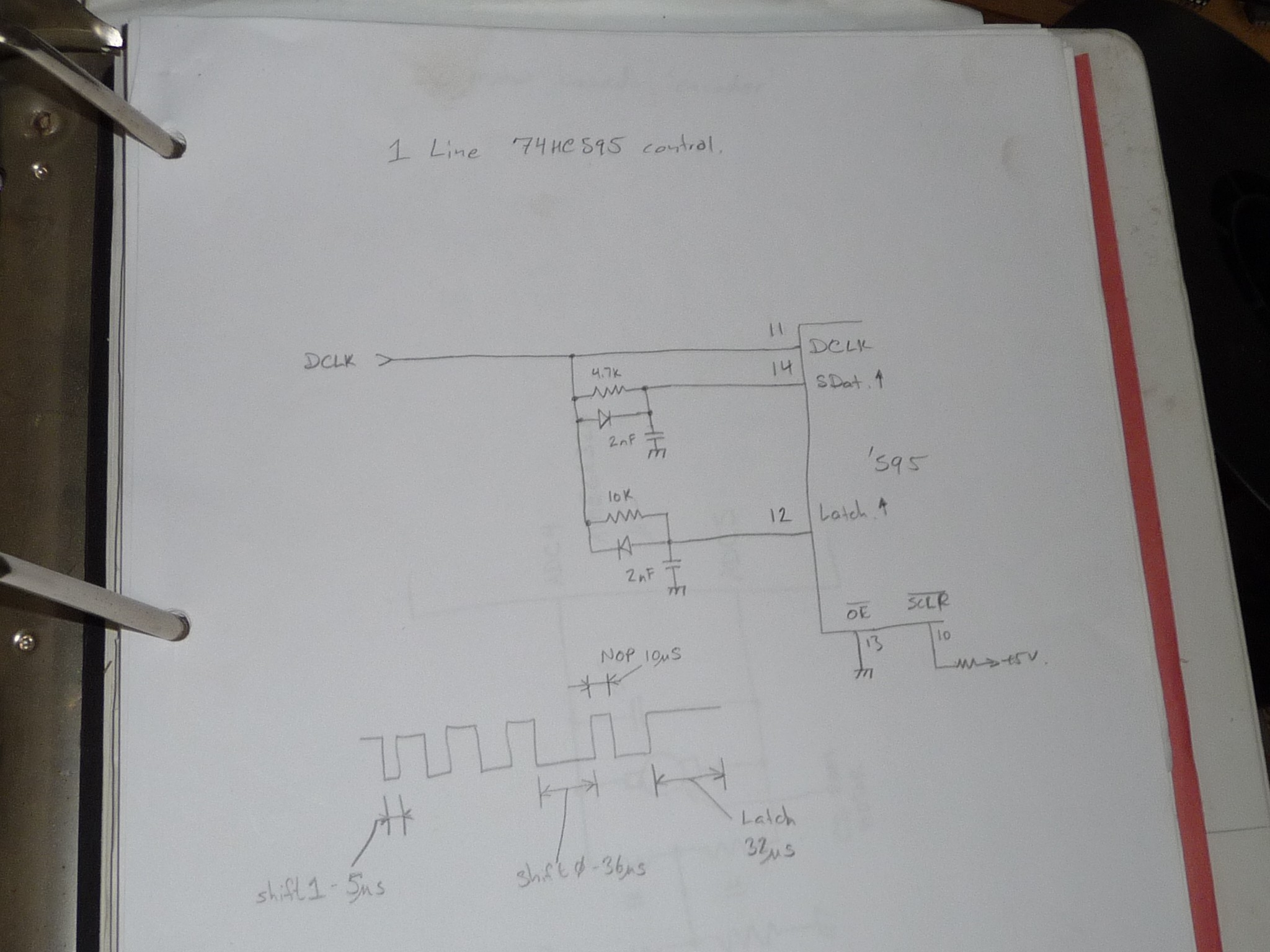
I'm quite sure I tuned the values and these times to have a descent error margin.
:] I honestly don't remember what the barrier times are :]
I have posted example source and schematic for the tiny13. It uses the 595 to generate a simple larson scanner on some LEDs.
https://github.com/ruenahcmohr/OneWire595/tree/main/tiny13
I have ported this to an esp8266. Here is the arduino source and wiring diagram:
https://github.com/ruenahcmohr/OneWire595/tree/main/esp8266-01
When adding the 74hc165 for return data, I had to adjust the timing a bit, The capacitors are bumped up from 2.2nF to 3.3nF, I suspect this is also to do with the fact the esp8266 is running from 3.3V.
Both the 74HC595 and the 74HC165 can be chained to get any multiple of 8 lines working, Due to the loading, I recommend that if you do this, you run the signals (post RC filtering) thru a set of 74HC14 gates to assist the chip drive and maintain the timing.
My code example assumes that for each byte sent, your getting a byte back. Keeping the output size the same as the input size keeps life simple :]
 mit41301
 Yann Guidon / YGDES
 Alvaro Barcellos
 Brandon Reinhart