Close
0%
0%

Radiant Dice

Geiger counter based random number generator/dice roller

Similar projects worth following
I was covering the randomness unit, with my students, in an Exploring Computer Science course. Through our discussion, using radiation as a source of true randomness, I was inspired to make a dice roller/random number generator. I did some internet sleuthing and got some inspiration from Chernobyl Dice.

On the electronics side, I used a Teensy 4.1 as the main board along with a Geiger counter from Mighty Ohm. Encoders allow for setting options.

I used the two spaces between three pulses to generate a zero or one. If the first gap is larger it’s a 0 of the second gap is larger it’s a 1. This creates 12 bit integers in a circular buffer that is constantly running. When you pull the lever, it will pop off the first number and map it to the given range.

I'm not an electrical engineer/nuclear scientist - be careful.

Operation

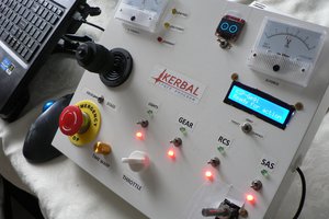
I wanted to be able to generate D&D (and other TTRPG) dice rolls, and random numbers between an upper and lower bound.  There is switch to change between the two modes. The three encoders allow you to change details. For dice rolling it is the quantity of dice, number of sides and a modifier. As you turn an encoder, it will switch the nixie tube display to that mode and allow you to change the value. In bounded mode you just need an upper and lower bound, so the middle encoder is not used.

The Teensy is constantly listening to the Geiger counter in the background and filling a circular buffer with 12bit integers. There aren't enough clicks to generate the values for big dice rolls on demand (like a fireball 8d6). So when you click engage, it will take values from the circular buffer and map them to the dice size required then add the modifier.

I added a preset option by clicking left encoder that will let you load a dice preset, I can't show the full dice line on the Nixies (e.g. 4d12+5) so you'll have to have a list of presets handy.

I also wanted to have my DM see the rolls, I decided to add an optional external display. I chose an Adafruit OLED since it's what I had around. The display shows the dice to rolled and the results. It's been helpful to have it around debugging as well.

Randomness

I am reading the time interval between three clicks to generate the random numbers. If the interval between clicks 1 and 2 is bigger than 2 and 3, it's a 1, otherwise its a 0. The bits are combined to make 12 bit integers. I chose 12bits since I'm trying to optimize the clicks I am getting and the dice rolls that I'm likely to make. I'm using the Arduino map() function to map the 12-bit integer to the required size. I let the counter run for a while generating a couple thousand d20 rolls it appears to be random (I gave the data to the AP Stats class in the building to verify).

Design

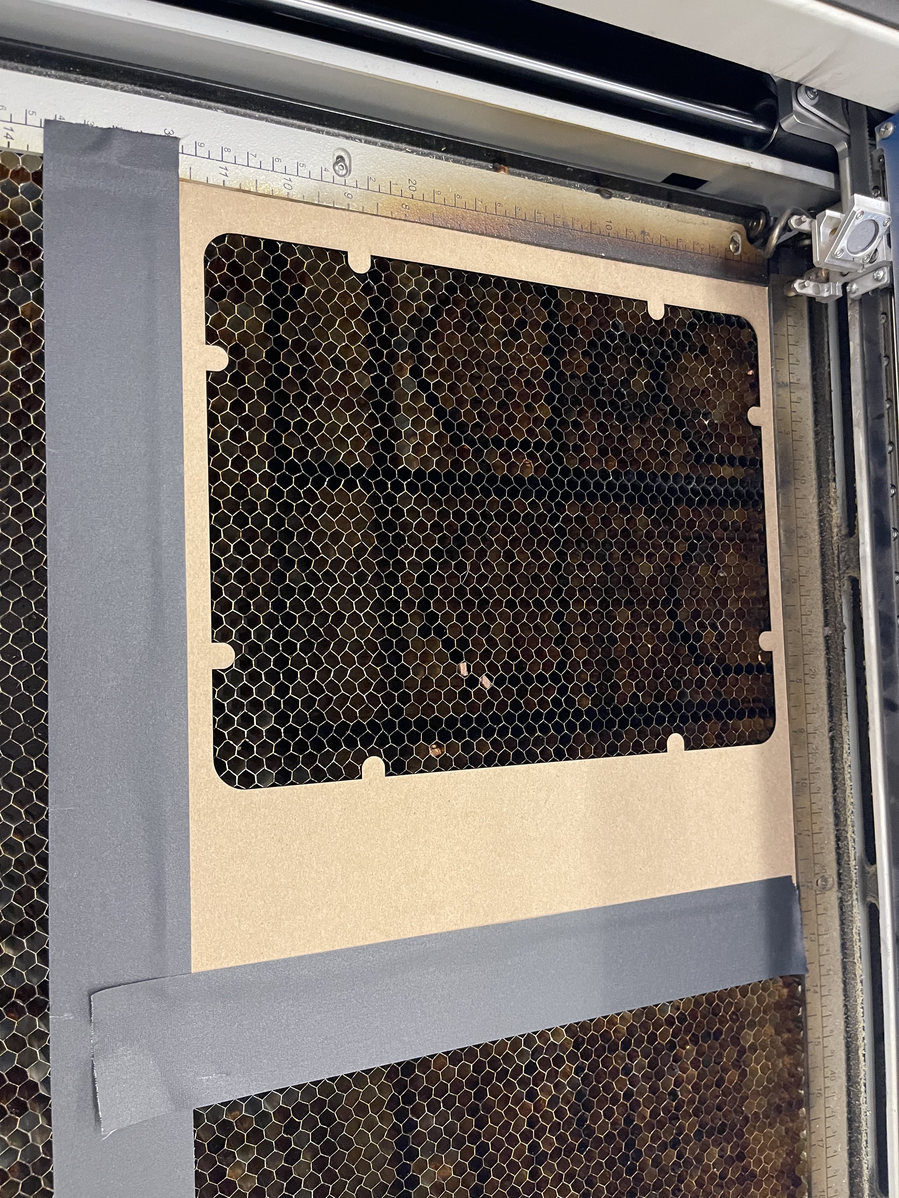
I'm used Autodesk Inventor for the 3D modeling of the panels, and supports. For the panels I made a 1:1 drawing of the panels exported it as a PDF, that I could pull in to Corel Draw to do the graphics (Corel Draws plays nicely with my laser). 

I did the circuit board in Fusion 360, it's my first circuit board, so it was quite the learning experience.

Components

Geiger Counter & Radioactive Source

I purchased a Mighty Ohm Geiger counter, which has an output pin that I can read with the Teensy. For the radioactive source, I choose a test card from United Nuclear since it would sit under the tube and be out of the way. The card generates enough clicks that I'm able to keep the number buffer happy.

Electronics

I chose to use a Teensy 4.1 for it's size and number of pins (I'm currently using around 2 dozen) plus an I2C bus.  I decided that I had to make a circuit board to simplify the wiring which quickly got out of control. This is my first circuit board, I plead ignorance on the best practices that I likely ignored.

Nixies

Nixies emphasize retro, and I've always wanted to use them on a project. I chose IN-12s since I didn't wanted to have them on a panel. I am using four IN-12A for the digits and one upside down IN-15A signal tube (i wanted the P (which upside down is a d) and + and - symbols. I was going to use SN74171 chips and level shifters, but then I found the Nixie Tester Driver boards which just simplified everything. I have a 12v to 220v power supply to generate the high voltage. I'm using nixie indicator dots on the knobs, these are switched with transistors. 

Uranium Marble & LEDs

I wanted to be able able to have something that looked like it was generating the random numbers. I chose to use a 1" uranium glass marble and 3 UV LEDs around it to generate the glow.

Fit and Finish

I found a bunch of old components on eBay to get the retro look I was going for:

  • Hickok model 203 meter to take the case from on eBay. 
  • 12V DC Cole Hersee Momentary toggle switch
  •  3...
Read more »

Acrylic Panel Layout.svg

The two acrylic sheets and the graphics.

svg+xml - 99.12 kB - 01/08/2023 at 02:55

Download

Radient Dice - Gerber.zip

Circuit board design - This is my first circuit board, I probably broke a lot of best practices, use with caution.

x-zip-compressed - 8.03 MB - 12/31/2022 at 19:45

Download

RadiationDice.ino

Code update 12/31

ino - 17.12 kB - 12/31/2022 at 16:20

Download

View all 15 components

  • A couple wins and a couple setbacks

    Andrew Woodbridge01/15/2023 at 02:28 0 comments

    The wins:

    • Indicators under each knob are working. I added a length of wire to each one, and put heat shrink over the joint. They went to the screw terminals, and it was pretty fast and easy. The indicators are a pretty tight fit, so I don't think I'm going to need to add in a 3D printed clamp for them.
    • The Bound/Rolled switch is wired and working. I had already coded this so it was just a matter of making sure that the direction was correct.
    • I swapped in the IN-15A symbol tube for the number tube.
    • Backpanel is cut and installed. I made a panel for the 5v/12v power supply, the high voltage nixie supply and the Geiger counter. I attached it tot he back of the case with Velcro strips. I had considered drilling holes and mounting it to floor, but this seemed simplest.
    • I revised the software run the indicators, and fixed the symbols so they correctly display now. I also worked on the negative number glitches. If you send a negative number to the nixie driver it will shut it off.

    Setbacks:

    • The Engage switch came faulty, I had to get a replacement.
    • Geiger Counter is dead. I mis-wired the pulse output and fried something. I misremembered the wiring and didn't look it up before testing. I'm working through that problem now.

    Next Steps:

    • Wire the GX16 Connector for I2C to go to the OLED
    • Mount UV LEDs and Marble
    • Replace Engage Switch
    • Take a lot of pictures

  • Front Panel Finishing

    Andrew Woodbridge01/06/2023 at 03:51 0 comments

    I completed the front panel today. 

    1. Laser cut 3mm white acrylic for the front and back layers of the panel
    2. Attached the panels together (IPS Weld-On 3 Acrylic Plastic Cement)
    3. Spray Painted them with a Matt Dark Green from  Rust-o-lium
    4. Taped down and cut a piece of cardstock for alignment, and burned away the paint leaving the white behind
    5. I then mounted everything.

    Up next:

    • Test/code the indicator lamps below the knobs
    • Design and 3D print a frame to hold the lamps, marble and UVLEDs
    • Cut the base piece which holds the power supplies and Geiger counter

  • The Nixies are Alive

    Andrew Woodbridge12/31/2022 at 16:15 0 comments

    Received and partially populated the circuit board. I wanted to test as I went since this is my first circuit board., and my first high voltage project. As I added components and test, everything seemed to be working without issue.

    On the code side, I updated the code to incorporate the Nixie Tester drivers, and the external OLED.

View all 3 project logs

Enjoy this project?

Share

Discussions

Keri Szafir wrote 12/31/2022 at 11:33 point

Interesting! Makes me wonder how the GM tube RNG is built.
Gives me an idea to get myself two E1T tubes (for the sheer coolness of them) and make a configurable multi-sided die.

  Are you sure? yes | no

Andrew Woodbridge wrote 12/31/2022 at 17:27 point

The Geiger counter is off the shelf, I'm just reading the pulses using the external connector on the board.

  Are you sure? yes | no

Similar Projects

Does this project spark your interest?

Become a member to follow this project and never miss any updates