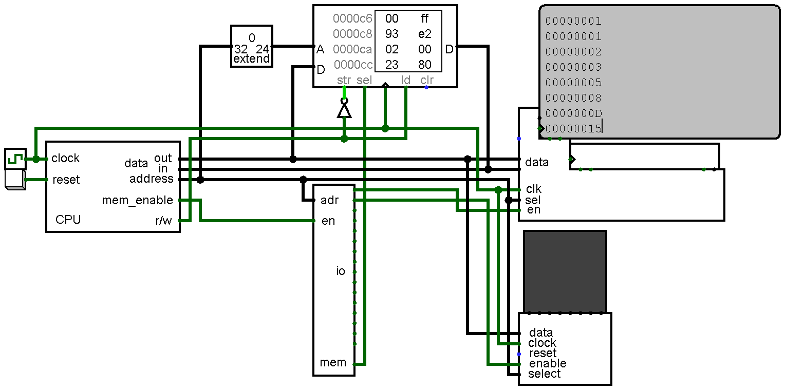
The primary goal of this project is to implement RISC-V in as few components as possible. risk-vee will be a microcoded design that sacrifices speed (an instruction fetch will take ~6 cycles) for size. Elegant it ain't.
I intend to make a post about each section of the circuit. I'll explain how it operates, give my reasoning for the design choices, and describe any ideas/tweaks for actually implementing it in hardware (although I have no intention of doing so at this point in time).
The next bit is where the obsessively anorexic design should start making sense: my #FO4CPU project will most likely end up being based on risk-vee. At first I was going with a toy design of mine that I dug up from a long time ago (~2011) with the intention of eventually creating a 6502. After seeing how simple RISC-V is that idea is pretty much scrapped for now.
Not to set my sights too high, but there is a small possibility of risk-vee eventually being able to run the RISC-V port of Linux. Doing so would require an MMU, interrupts/traps, and the addition of control & status registers.
Lastly, this project was inspired by @Phil Wright's #Worlds first 32 bit Homebrew CPU project.
All feedback is welcome.
 kaimac
 Erik Piehl
 Martian
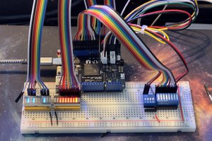
 Tom
Tom
This is amazing! Thanks for sharing.
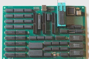
I was coming to risc-v from another angle : can an rv32i be built on breadboards with 74hc chips, ROMs and a sram for regfile. I started drawing modules on paper ( e.g. immediate decoding and extension) but definitely want to study your design.
Cheers