Close
0%
0%

RT Soldering pen

Soldering pen for Weller RT tips with OLED display

vlkvlk
Public Chat
Similar projects worth following
Starting from
$70.00
vlk has 247 orders / 15reviews
Ships from Slovakia
Every hardware hacker need good soldering tool. My idea was to build own but with very specific qualities. On one side not so expensive, on second side high quality and also small with precise control and features. I found some projects where is used Weller soldering tips designed for WMRP soldering iron with standard 3.5mm jack and inside the tip is also thermocouple for sensing temperature. These tips are not so cheap but the quality is really great, especially for fine soldering. Hardware design is based on similar projects but with many modifications and improvements. Also my request was to make the hardware small as possible to fit into handle and capable to supply from hobbyist LiPO battery.Buy one on tindiy: https://www.tindie.com/products/vlk/rt-soldering-pen/

Features:

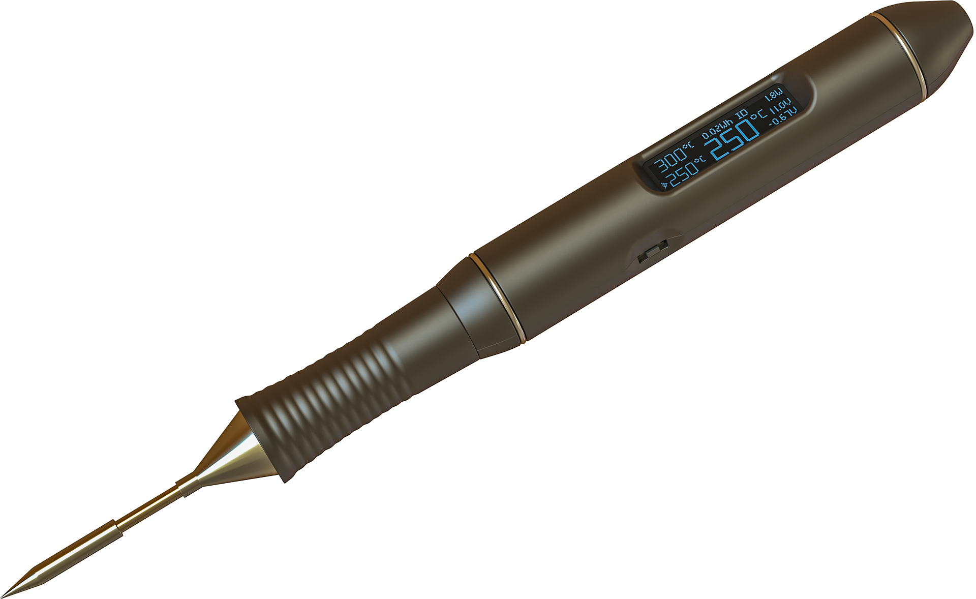
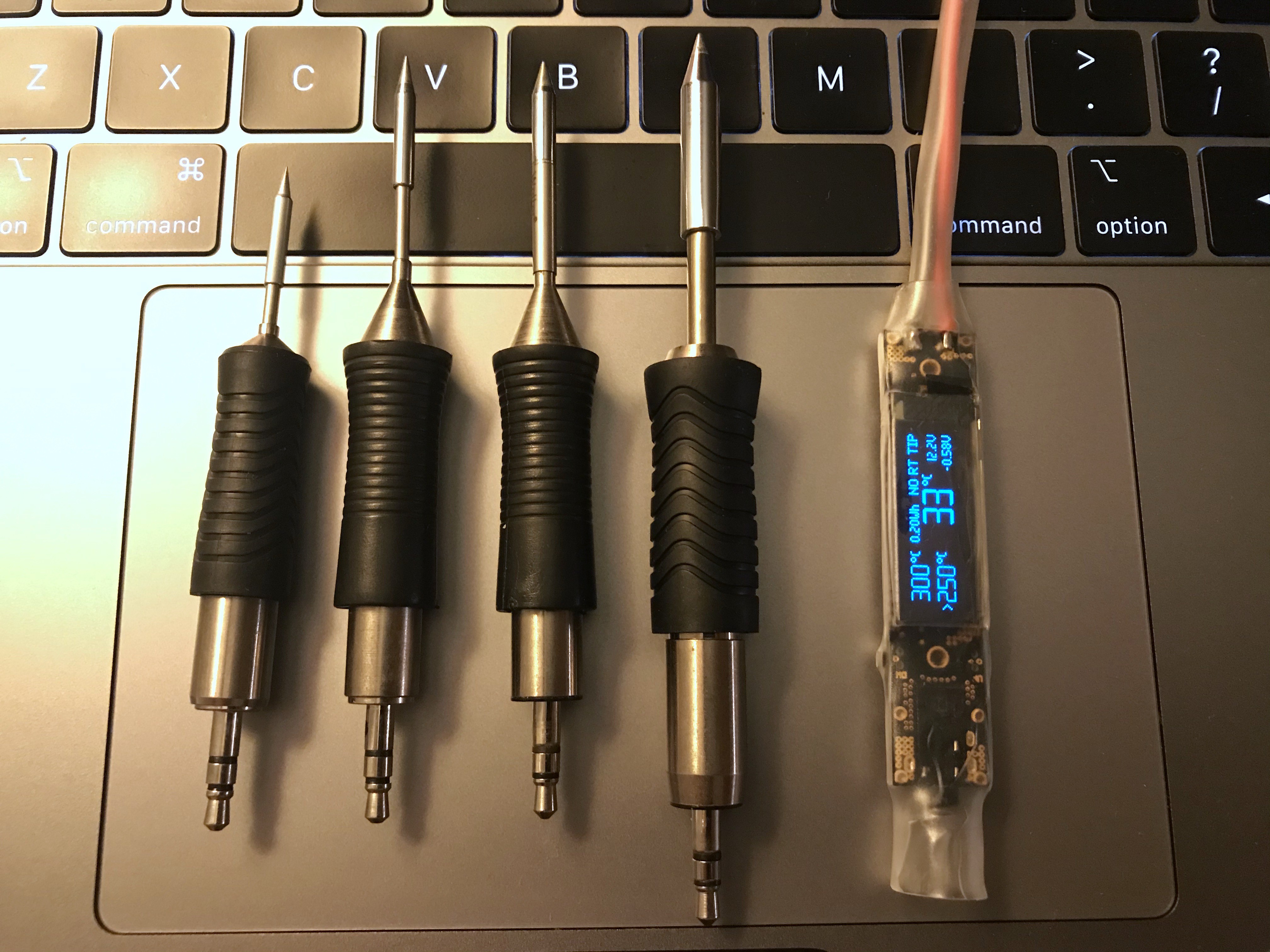
  • very compact - will fit into handle
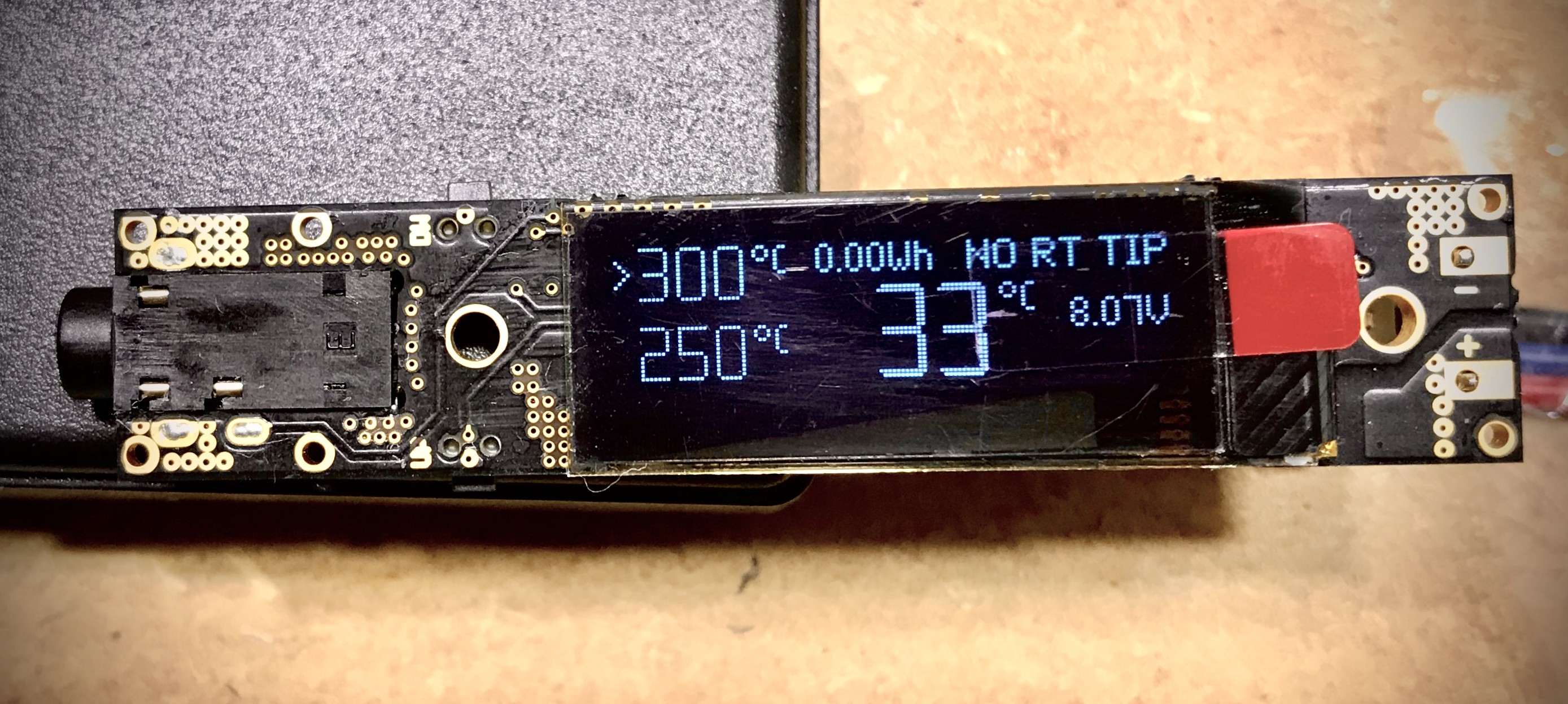
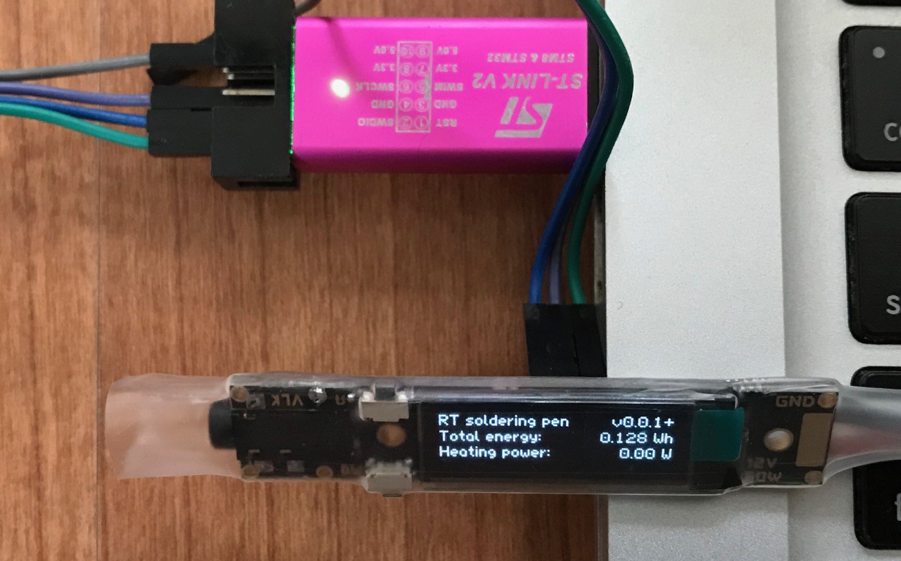
  • display show status, preset and tip temperature, power, supply voltage, drop, ...
  • two buttons
  • automatic standby
  • sensing supply voltage and tip current
  • precise regulation with PID (PSD controller with some modifications)
  • supply voltage is from 5V to 18V (best is 10-13V)
  • designed to supply from LIPO battery 2S (7.4V max is about 18W) or 3S (11.1V max is more than 40W)
  • calculating consumed Wh
  • heat-up in 5sec from 25 to 400°C (with 40W limit)
  • Idle current about 8mA

What is planed:

  • case
  • battery monitor (warn when battery need charge)
  • configuration editor for some constants from PSD controller, power limit, ....
  • open-source everything

Videos:

Weller-RT6-Holder-Bottom-V1.0.stl

RT pen case bottom part for HW v1.0

Standard Tesselated Geometry - 9.53 MB - 12/08/2019 at 19:15

Download

Weller-RT6-Holder-Top-V1.0.stl

RT pen case Top part for HW 1.0

Standard Tesselated Geometry - 4.78 MB - 12/08/2019 at 19:15

Download

Portable Network Graphics (PNG) - 64.37 kB - 03/30/2017 at 19:45

Preview
Download

  • 1 × STM32F031 Microprocessors, Microcontrollers, DSPs / ARM, RISC-Based Microcontrollers
  • 1 × AD8551 Precise operational amplifier
  • 1 × ACS711 Hall effect current sensor
  • 1 × LMR14203 Power Management ICs / Switching Regulators and Controllers
  • 1 × OLED display 0.91" 128x32

  • Display replacement

    vlk05/02/2023 at 09:25 0 comments
  • New HW revision v1.1

    vlk02/08/2021 at 21:00 0 comments

    - new switches

    - updated layout with fixed current sensor connection bug

  • RT PEN CASE

    vlk12/08/2019 at 19:22 4 comments

    Otto Winter send me STL files with case design for HW v1.0

    Bottom part: Weller-RT6-Holder-Bottom-V1.0.stl

    Top part: Weller-RT6-Holder-Top-V1.0.stl

  • About new RT tips

    vlk12/08/2019 at 18:55 0 comments

    RTM, RTP and RTU tips

    Weller this year introduced new series of RT tips with nice slogan "No compromise".

    There are three types:

    • RTM - RT Micro - they are same like previous line RT, but with new naming
    • RTP - RT Pico - these tips are smaller, shorter for more precise soldering
    • RTU - RT Ultra - these tips are in opposite bigger and designed for higher power (till 150 Watts)

    All the tips have same pinout and in general are compatible,

    RTM and RTP (also previous RT) have resistance of heating element 2 Ohm and they are designed for 12 V (current is 6 A) but maximum average heating power is 40 Watts - this power is controlled and limited by PWM.

    RTU has resistance of heating element 3.5 Ohm, this mean, to reach 150Watts is necessary to use higher voltage - at least 24V, but the current will be still similar - what is good for the JACK connector.

    But actual design of RT soldering pen has limitation for power at 18 V and current to RT, RTM and RTP will be at 18 V: 9 Amps - the pen it should withstand it, because average pulse power is limited by SW to 40 W) question is what can withstand the JACK connector.

    The main question is how to use this with RTU tips they need 24 V. so, absolute maximum rating of HW 1.0* is 25V for supply voltage (limiting element is input capacitor) after replacing input cap next limit will be 30V (maximum voltage of MOSFET switches)

    *Absolute maximum rating for previous HW v0.3 is 20V - this is limited by 20V MOSFET switch.

    For RTU if the supply will be 24V then output power can be near to 150 Watts, but this need also modifications in SW to allow higher output power. Yes, this is planed and new release will available be soon.

    Another problem with new tips is that each kind RT/RTM, RTP and RTU has different dimensions of the cylinder on JACK side and is necessary to count with this for case design. (old RT and new RTM have same dimensions of the cylinder) this is also reason why Weller sell for each kind different tip holder.

    MS tips:

    If I talking about tips there is one more question: What it mean if in name is "MS", it mean that tip meets Military Specifications. But there is no more informations. In general the main different is that shield of the tip is electrically isolated from the connector, standard tips have shield connected to ground.

    Weller RT TIP typemax average powerheater element resistancecurrent  and power at 12Vcurrent and power at 16Vcurrent and power at 24V
    RTM / RT40W (55W*)6A / 72W8A / 128W-
    RTP
    40W6A / 72W8A / 128W-
    RTU150W3.5Ω3.4A / 41W4.6A / 73W6.8A / 164W

    * some RT tips have 55W limit (RTM 36 S / RT 11)

    from left: RTP, RTM, RTM MS, RTU

  • New RT tips

    vlk10/06/2019 at 20:14 1 comment

    just found, that Weller announced new RT soldering tips

  • New firmware v0.4.0

    vlk10/06/2019 at 20:06 0 comments

    New firmware is ready to download, it support HW v0.3 and also new HW v1.0.

    features:

     - display brightness control

    - turn off display to protect pixels burning when is inactive for 15 minutes (wake up by pressing both buttons at once)

    - increased maximum preset temperature to 500°C (only for HW v1.0)

    https://github.com/pavelrevak/rt_soldering_pen/releases

  • New redesign is ready

    vlk09/26/2019 at 18:30 1 comment

  • New HW

    vlk05/07/2019 at 18:36 3 comments

    After longer delay, after some troubles, new revision is getting ready.

    There will be two major enhancements:

    • full reverse polarity protection
    • added accelerometer

    Stay tuned..

  • New version of Firmware v0.2.0

    vlk08/09/2018 at 18:14 0 comments

    Main changes:

    - improved PID

    - saving preset temperatures

    List of all changes and download: https://github.com/pavelrevak/rt_soldering_pen/releases

  • New version of Firmware v0.1.0

    vlk07/24/2018 at 21:29 0 comments

    Although is still in development state is stable and has many new features, like simple main screen with large temperature, Fahrenheit mode or left-handed mode.

    There is also many features in background

    Update is easy and safe with any SWD (ST-Link) programmer

    Download from github: https://github.com/pavelrevak/rt_soldering_pen/releases


    Updating firmware with cheap Chinese ST-Link programmer:

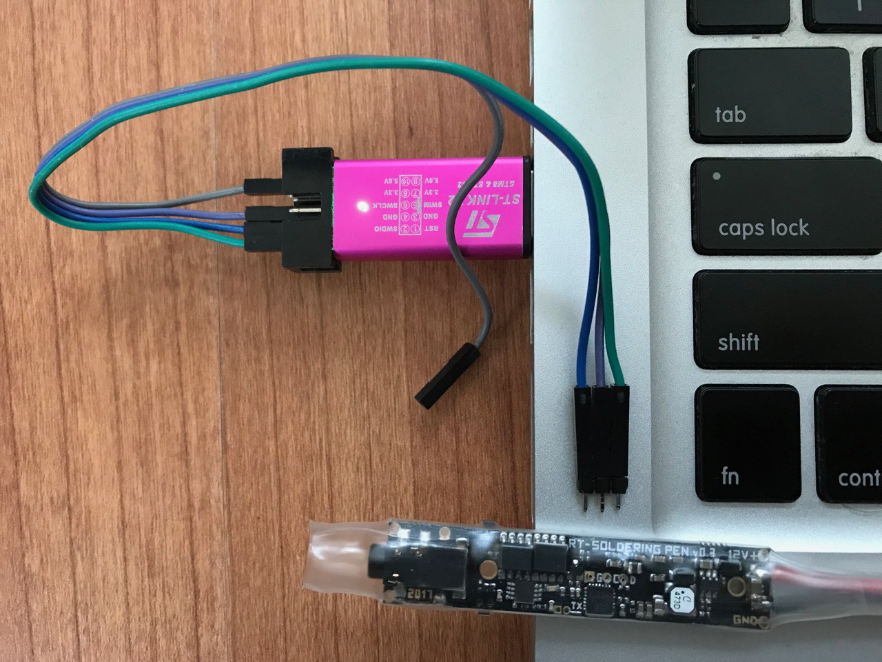
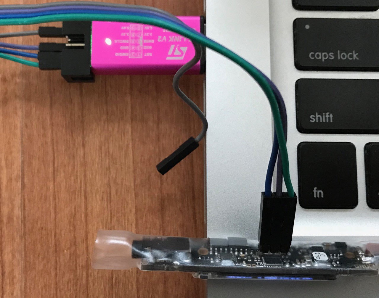
    To program, use ST-Link utility from ST, or any other SW for Flashing STM32 micro-controllers (openocd, texane/stlink, pystlink, ...)

    There is also possible to use ST-Link part of any Discovery or Nucleo board.

View all 18 project logs

Enjoy this project?

Share

Discussions

Chris Roberts wrote 07/30/2019 at 09:07 point

I love this, It would be really cool if it could have a USB-C PD connection. I carry about a big high power USB C battery bank and it would be very convenient if this could have something like a STUSB4500 integrated to get the most out of it. this is where the TS80 is lacking.

  Are you sure? yes | no

vlk wrote 12/13/2019 at 16:44 point

Hello Chris, there is a problem with USB-C because at 12 V there are 6Amps pulses and not all  power sources can withstand this load. Normally USB-C PD can deliver at 12V 3 Amps. (maybe some power supplies can deliver at 12V 5Amps)

In general the average power load is still smaller than USB-C PD power supply, so some filters with high capacity can help to decrease the current peaks.

If you still want to use USB-C you can use ZYPDS (it is easy to pack it because it has same width like my board)

  Are you sure? yes | no

Romain wrote 07/28/2019 at 09:47 point

Hi there,

Just wanted to let you know I'm very interested in your project.

Do you know when the HW revision is going to be available?

Also, I wanted to design a 3D printed case for this (with two side that can be clipped or screwed together). Would be interested if I shared the design?

Cheers!

  Are you sure? yes | no

ovDarkness wrote 04/28/2019 at 20:56 point

Dear Vik,
I work with industrial 3D printing and CNC, I can help with design and manufacturing of a case for your project. I'd also gladly buy one for myself :D
Please contact me if you're interested in cooperation. We're just over the border - in Poland :)

  Are you sure? yes | no

Manu wrote 04/23/2019 at 14:09 point

Hi, great project! What is limiting the input voltage to 15V?

  Are you sure? yes | no

warleyssant wrote 03/11/2019 at 18:50 point

When will it be available in tindie? I want to buy

  Are you sure? yes | no

Chris wrote 01/26/2019 at 03:02 point

@Otto Winter It's been more than a few days, and I'd kill for that case. Do you have any updates?

Any updates for this project in general? The repo is active but this page hasn't been updated in a while.

EDIT: Or, as Hikopan pointed out the board has been out of stock since October, has this project been abandoned?

  Are you sure? yes | no

Otto Winter wrote 05/13/2019 at 13:02 point

@Chris

you don't need to kill for this case, I can send you the STL File.
Never forget, we are a ordinray people and not a Company and we have our private Life as a FIRST Prionity and much later coming our hobby!
I don't look every day or every weeks this page... Sorry!

Now you make it yourself, congratulation.

Best Regards

  Are you sure? yes | no

Chris wrote 05/13/2019 at 14:45 point

@Otto Winter Of course! Sorry if I came off as impatient or demanding, I was just very impressed and eager to build my own. Weller tip compatibility make this more appealing than TS80 and your enclosure looks phenomenal.

A copy of the STL file would be hugely appreciated!

  Are you sure? yes | no

elektrinis wrote 01/07/2019 at 20:15 point

So is the case/enclosure STL available yet? It's been over 6 months now...
I have cracked two screens already due to it being in a heatshrink.

  Are you sure? yes | no

elektrinis wrote 01/11/2019 at 18:04 point

Never mind, designed and printed my own.

  Are you sure? yes | no

Jarrett wrote 01/11/2019 at 19:25 point

Got a link? Sounds like some other people here would be excited about that ;)

  Are you sure? yes | no

xorlosch wrote 06/20/2020 at 12:24 point

i just cracked my screen when trying to fit it into the too narrow case. what did you do? could you replace the screen with a new one? and how? i would also like to repair mine as the display is not showing anithing anymore. thanks

  Are you sure? yes | no

Hikopan1972 wrote 11/12/2018 at 08:29 point

Hello !!

I want buy a soldering pen board but it seems out of stock now , will it be available soon ? Thanks 

  Are you sure? yes | no

Branimir wrote 10/16/2018 at 10:40 point

Hello!

Do you sell any naked PCBs?I'd like to assemble it on my own,if i have this option.

  Are you sure? yes | no

Messschuh wrote 09/07/2018 at 19:18 point

got mine RTsp few month ago and i also have the TS100. the TS100 is OK for use at home with a notebook power supply or so, but for mobile use with 12 volt or a 4s lipo battery the performance isnt really great. i use the genuine rt weller battery solder since many years at work, i love this tool it works great, but for privat use it is to expensive. so i bought the RT soldering pen and i‘m really happy with it.  in my opinon it works better than the original one. 

i want to upgrade the firmware, still have V0.0.1 , but i have no idea how it works. bought the st link v2 and try to upgrade but i have absolutly no idea what to do.  is there any tutorial avalible  how to upgrade the firmware??? allready read the „readme.md“ at github but it dosent help me. so maybe someone have a link for a tutorial or can help with some helpful tips. ?

  Are you sure? yes | no

Jarrett wrote 09/07/2018 at 19:26 point

hi Messschuh,

I'm not associated with this project in any way, but the directions look fairly straightforward (to me, someone who is comfortable with embedded toolchains).

Where are you lost?

It looks like there are two main components:

1. Physically hooking the STLink up to the soldering iron. There are pictures above on how to do it, and the readme.md shows the exact wires you have to connect.

2. Getting / compiling / flashing the firmware. Basically, with the STLink programmer connected, run all of those commands in the readme.md on the terminal. Only for Linux / Mac, Windows would have a very different (and not recommended) workflow

  Are you sure? yes | no

vlk wrote 09/07/2018 at 20:58 point

Hello Messschuh, thanks for asking, that is true that I don't have very detailed tutorial to update firmware (for non-programmers), I will improve it!

For now you can download the compiled version of firmware (.hex or it will work also with .srec or .bin) from github: https://github.com/pavelrevak/rt_soldering_pen/releases/tag/v0.2.0

so you don't need to install any toolchain and build it.

Then if you are on windows you can download clickable flashing tool - stlink-utility from ST: https://www.st.com/en/development-tools/stsw-link004.html (probably for download you need to register into st.com)

And with this utility you can flash the new firmware. it is easy and safe, but I suggest you to remove the soldering tip before updating and if the firmware will run successfully (also check the version if is v0.2.0) then connect the tip and test it.

So, if you will have any problems, send me email or private message and I will try to help you directly.

  Are you sure? yes | no

Messschuh wrote 09/08/2018 at 11:39 point

wow, thx guys for fast answer . 

about the wiring, that isnt my problem. im not „stupid“ at all,  i can programm an arduino, i can programmm a cs 8635 bluetooth receiver and so on...., but i still have no experience with the st. maybe i can do a tutorial when i check how it works.  luv this project, and would be happy if i can support it.

 thx again for quick response guys u are awersome.

  Are you sure? yes | no

Messschuh wrote 09/10/2018 at 16:02 point

OK, got it. Downloaded the ST tool and the hex file the rest was self-explaining. It`s so easy if how to know. :)

  Are you sure? yes | no

Otto Winter wrote 08/29/2018 at 14:30 point

The new case is born!
In the next days the STL Data, for 3D printing would be available...
Here is the "perliminary" picture: www.global-motions.com/ftp/RTSP-V0.6-1.jpg

  Are you sure? yes | no

Jan wrote 08/29/2018 at 20:36 point

That background! Can you add a space cat surfing on the handle as well? Would be awesome. Jokes aside: that looks really comfortable to hold and work with. Nice job!

  Are you sure? yes | no

Otto Winter wrote 08/29/2018 at 22:53 point

Thank you, sorry, a white background looks really bad ;-)

  Are you sure? yes | no

nickwrgggdd wrote 08/31/2018 at 00:04 point

Otto that case is amazing to you actually have that DC cable can you link me to it?

  Are you sure? yes | no

nickwrgggdd wrote 09/03/2018 at 16:47 point

otto have you printed a prototype of your design yet idk if 3d printing is the way to go what method do you recommend using to print that. What your going for it might be better to get a bunch injection molded and have vlk sell them with/ as addon to his pen. I just dont know what wuld be the best way 

  Are you sure? yes | no

JaneDoe wrote 09/04/2018 at 16:28 point

I seem to remember injection moulding beeing Very Very expensive...

That's why we have a 3D Printing industry going ;)

Otto's render of the case look stunning.

Just got a RT tip for my controller, d*mn this thing heats up fast :D

  Are you sure? yes | no

Otto Winter wrote 09/06/2018 at 11:34 point

I let it 3D printed with MJF (SLS like) method by www.rapidobject.com.
Two complete cases for 35€. Yes it was not cheap...
If you have a good 3D Printer, you can try to print it yourself.

  Are you sure? yes | no

Messschuh wrote 09/07/2018 at 19:22 point

really nice work otto,  when the stl is avalible i will try to print it with my fdm printer.

  Are you sure? yes | no

nickwrgggdd wrote 09/29/2018 at 04:08 point

Otto ETA on STL data??

  Are you sure? yes | no

boehme.peer wrote 06/07/2019 at 19:38 point

That looks realy good. Are the STL Files available? I would try to print it on a sla printer.

  Are you sure? yes | no

Arne Wichmann wrote 08/25/2018 at 14:57 point

I designed an experimental Housing: https://www.thingiverse.com/thing:3066792

  Are you sure? yes | no

vlk wrote 08/25/2018 at 20:09 point

Hi Arne, it is very original design, nice! thanks for sharing it.

  Are you sure? yes | no

nickwrgggdd wrote 08/26/2018 at 08:30 point

Hey thanks for sharing the design i got this part printed using SLS for 22.26 at sculpteo it would of been cheaper but i got polished finish will post pics when it arrives they were the cheapest i found if anyone else is intrested

  Are you sure? yes | no

Arne Wichmann wrote 08/27/2018 at 14:16 point

I just noticed that I had a bug in the design (measured from the knob of the buttons, not the corner of the button housing). I have fixed it on Thingyverse. Maybe you can still change your order? (My print of the buggy design still worked, but the buttons were quite off...)

  Are you sure? yes | no

nickwrgggdd wrote 08/27/2018 at 16:08 point

i was able to update design as it was printed yet guess im lucky i ordered on a weekend again thankyou so much

*Also have you printed this? Mind posting pics?

  Are you sure? yes | no

Arne Wichmann wrote 08/27/2018 at 17:03 point

https://www.thingiverse.com/make:530872 simple black PLA-extrusion print, with bad light conditions :)

  Are you sure? yes | no

Arne Wichmann wrote 09/05/2018 at 15:07 point

I have tweaked my design a bit: https://www.thingiverse.com/thing:3084826

(Currently untested.)

  Are you sure? yes | no

nickwrgggdd wrote 08/24/2018 at 22:35 point

confirmed xbox 360 powersupply powers it perfectly

  Are you sure? yes | no

nickwrgggdd wrote 08/19/2018 at 22:47 point

For anyone wanting to use somthing other than lipo to power this an xbox 360 slim power supply should work quite well the can be found quite cheap on ebay. NOTE I have not tested this yet but was informed by other that this psu can support the high 6-8 amp pulsing. and i will be using a xt30u connector to make a nice connection while still maintaining portablity. I will update later this week when i recieve the psu. https://ibb.co/ncqCdK 

Also Otto Winter i dont know what type of connector your incorporating to fit with your 3d print design but alot of lipo batterys come with xt30 or jst xt30 supports higher amp rating without getting to hot

  Are you sure? yes | no

nickwrgggdd wrote 08/19/2018 at 22:54 point

only reason i thought of xt30 was w/ a case i think it would make a nice snug connection rather then just placing a jst over the 2 prongs

  Are you sure? yes | no

Otto Winter wrote 08/15/2018 at 09:16 point

The new Firmware V0.2.0 working fine with  LiPo 4S 3000mAh (14,8V) !
Thank you :-)

  Are you sure? yes | no

nickwrgggdd wrote 08/01/2018 at 14:03 point

hey just wana make sure this pen doesnt have to be powered by a Lipo battery correct? Im planing on using a 12v or 14v 3amp power supply if im reading correctly that should work itll be about 42w

  Are you sure? yes | no

vlk wrote 08/01/2018 at 20:05 point

Hello, it is not easy, because it has pulse current, with peak dependent on supply voltage, peaks are short but they are at 12V 6A or at 16V 8A. although the current is high average power will be at maximum 40W, so if the supply will have strong capacity bank, it will be work.

  Are you sure? yes | no

Otto Winter wrote 07/27/2018 at 15:39 point

I've found something that can kill the RT Solder Pen!
If somebody do not pushing the RT Pen full in the socket, you do not have any values from thermostat and the pen glowing with orange color !!!
In the software, you should prevent heating the pen, without sensing the thermostat resistance!
Best Regards
Otto

  Are you sure? yes | no

vlk wrote 07/27/2018 at 19:00 point

Hi Otto, thanks for reporting, I have in software this state but detecting code is not implemented right now, so this is good reason to do this.

Hope your RT TIP survive this shock.

There is also other problem if somebody connect supply in reverse and TIP is connected, then MCU is protected by diode, but TIP not (due to large drop voltage on diode) and it get full power through diode inside MOSFET.

  Are you sure? yes | no

Otto Winter wrote 07/27/2018 at 23:21 point

My RT TIP is Ok because I did disconnected it fast enough...
For the revese power connection I don't see any solution, because of no place for such high current protection circuit!
The user should look for the correct polarisation of the Power connection...
You can put one 10-20A shottky diode between plus and minus wires.
If the User connecting it wrong they get only a short circuit and your controller is saved from burning out.


  Are you sure? yes | no

Otto Winter wrote 07/27/2018 at 12:33 point


Hello, now I got your new Board and it is perfect and working well!
In the next weeks I'll change my prior designed enclosure and give it free for 3D printing here.
Best Regards
Otto

  Are you sure? yes | no

vlk wrote 07/27/2018 at 19:04 point

Hi Otto, thanks for the order and also big interest to create enclosure, we will looking forward for the design, thanks!

  Are you sure? yes | no

nickwrgggdd wrote 07/24/2018 at 00:23 point

Where are the Solder Points on the board for Programming the STM32

  Are you sure? yes | no

vlk wrote 07/25/2018 at 08:56 point

These pins are near to MCU in middle of PCB and marked G, C, D (GND, CLK, DATA).

Look on these pictures: https://hackaday.io/project/18899-rt-soldering-pen/log/149976-new-version-of-firmware-v010

  Are you sure? yes | no

ivan003003 wrote 06/29/2018 at 14:02 point

Hello there Mr.vlk

I have read carefully the technical characteristic of your RT Soldering pen.

I'm really in love with it and i'm very excited to buy it,at least one :)

However,for me the only one problem is this : 

i can't go to buy this item raw as it is now!

without any kind of enclousure and an incorporated power plug.

I really hope that you & Otto Winter will release the RT soldering pen in final version,with the enclousure and the incorporated power plug.

Thanks you very much !

  Are you sure? yes | no

vlk wrote 07/08/2018 at 05:37 point

Hi Ivan, enclosure is planed

  Are you sure? yes | no

ivan003003 wrote 07/10/2018 at 17:47 point

I'm very,very glad :)

  Are you sure? yes | no

Similar Projects

Does this project spark your interest?

Become a member to follow this project and never miss any updates