 Arya
AryaWant to make a simple part quickly? Here's a 3 minute guide!
This guide doesn't fit your requirements and you need to draw a part from the scratch? Follow this:
A 3 minute guide, as well as a "from scratch" guide
Already have an account? Log in.
To make the experience fit your profile, pick a username and tell us what interests you.
Want to make a simple part quickly? Here's a 3 minute guide!
This guide doesn't fit your requirements and you need to draw a part from the scratch? Follow this:
If you want to create your very new part, here's the short way to do it:
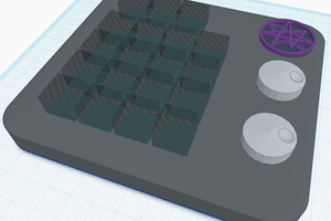
A very simple footprint. Fritzing generates those automatically, again, and this is how it looks:
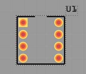
Couldn't have done it simpler.
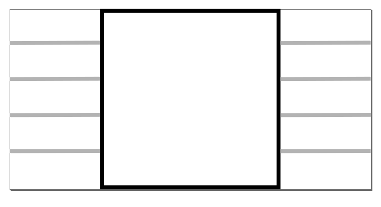
We're aiming for a simple schematic symbol - a rectangle, pins from both sides matching the physical pinout and text labels with those.
Canvas dimensions:
Draw a rectangle, no fill, black outline with 1px stroke width. Dimension it to 0.5x0.5in and center.
Draw a straight line, set width to 0.25 in and height to something like 0.012. Move first row of lines to X:0.0in and Y:(0.1, 0.2, 0.3, 0.4)in. Second row goes to X:0.75in and same Y.
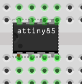
Everything is autogenerated. For even better effect, select the part and go Part->Edit . I didn't even need that to make an ATTiny.
Read more »The SVG we'll need to draw will be a little larger though to look nice and be perfectly aligned with the grid. Let's say pin rectangle height will be 0.035.
Modifications:
Resulting dimensions for ATtiny85:
The footprint I got minified is a good template. I could just put "ATtiny85" into "ic_text"... come to think of it, it's already there. However, let's make it from scratch! There'll be issues like grid sizes and dimensions and it would be unfair not to get those sorted out.
Woke up, continuing work. Does the size even matter? I measured the real Tiny's dimensions and they weren't to scale with the SVG. Let's scale our ATtiny85 in Inkscape to those dimensions and find out:
Well. First of all, I enlarged that footprint but it shrinked. Second thing - Inkscape fucks up the SVG, making it unreadable:
Read more »Nothing's better than reverse-engineering, right?  Well, maybe I can actually learn something from the existing parts, especially provided there are so many DIP-8 ICs shipped with Fritzing. I'm creating everything from scratch, but this saves my frustration for me and time for readers.
Fritzing is huge - 182MB archived, 360MB unpacked. I can go make hot chocolate while the archive is unpacking.
Read more »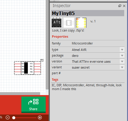
 mrpendent
 Mike
Mike
 Corey Benn
 deʃhipu