Close
0%
0%

G-EDM

Sinker EDM with drill chuck and multi-toolhead for cutting and drilling metal

Similar projects worth following
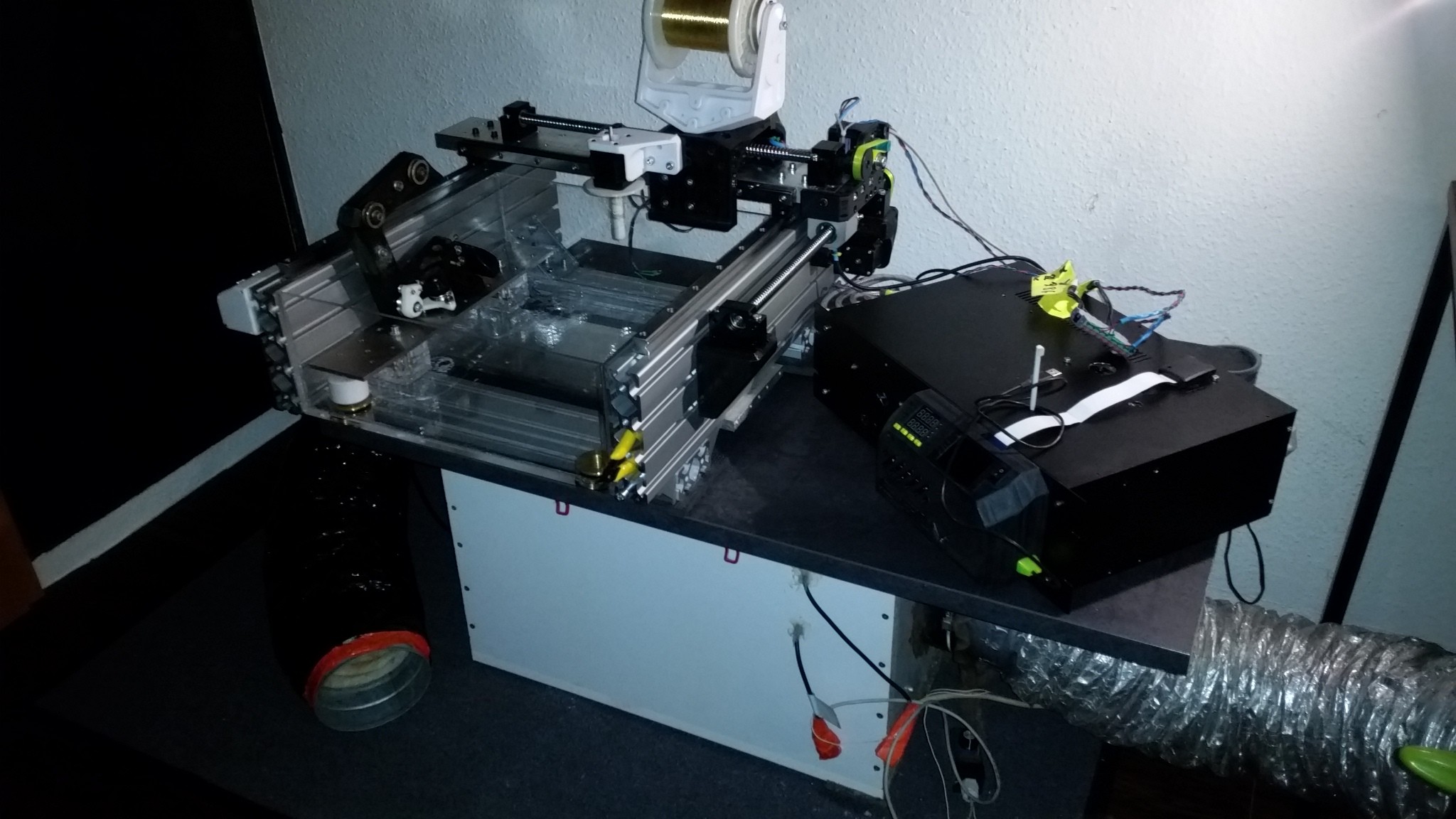
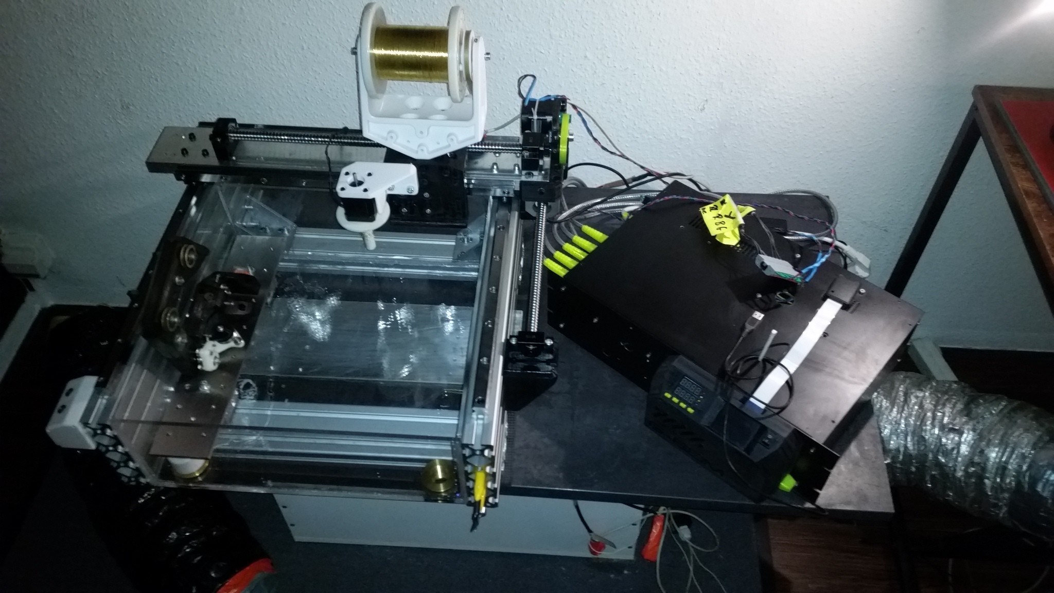
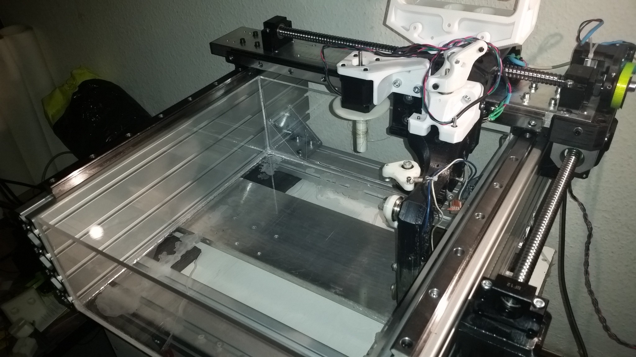
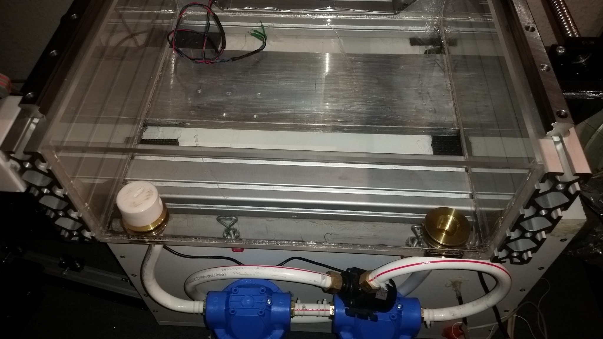
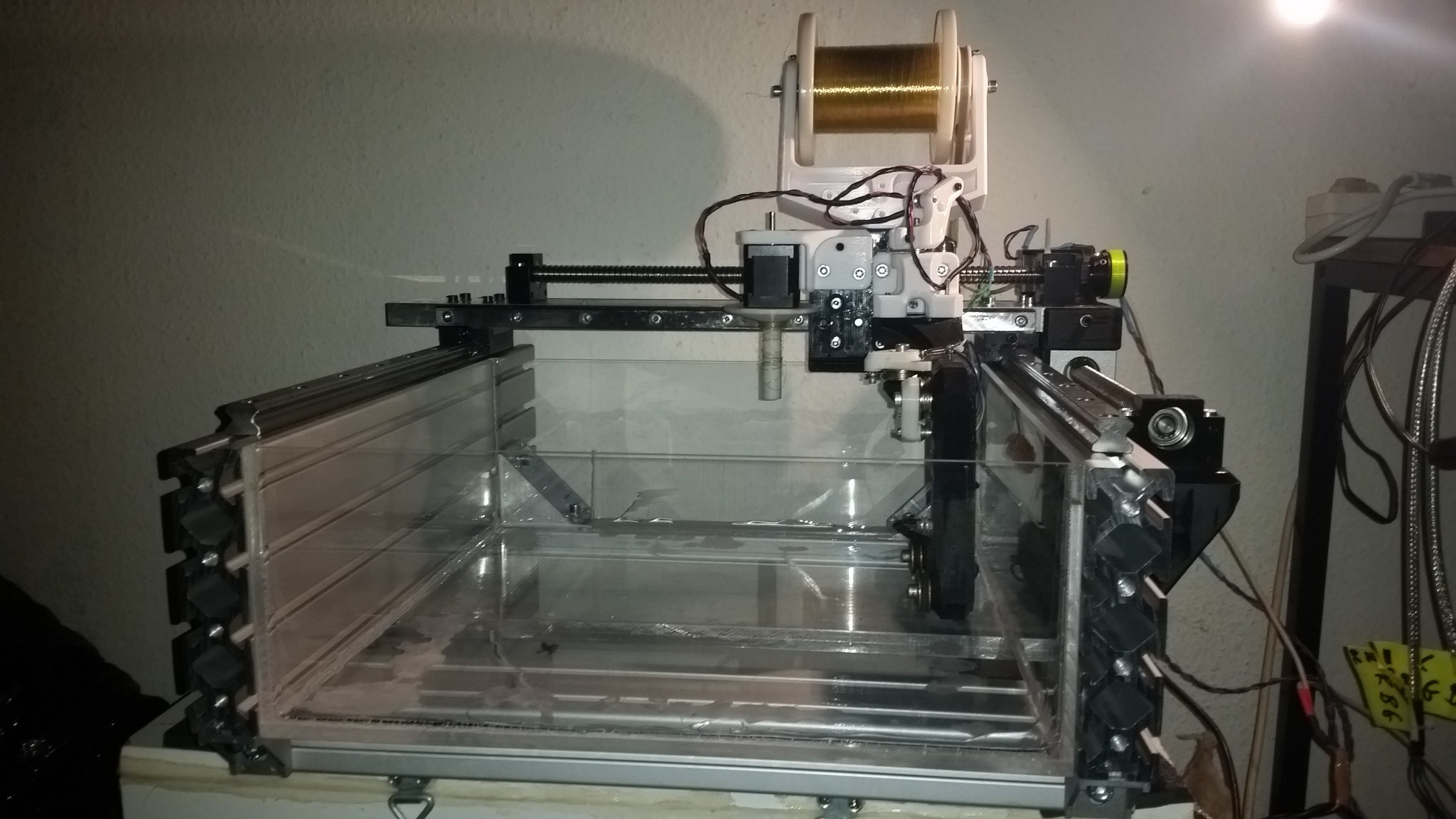
The G-EDM is a fully automated one axis sinker EDM machine that supports different kinds of electrodes like brass tubes or brass sheets
and is highly customizable.

It can fit almost any kind of N-channel mosfet to support higher currents and the pulse generator PCB can easily handle 10 Amps of constant current.

It uses 3D printed parts where it is possible.

The G-EDM ( new video )


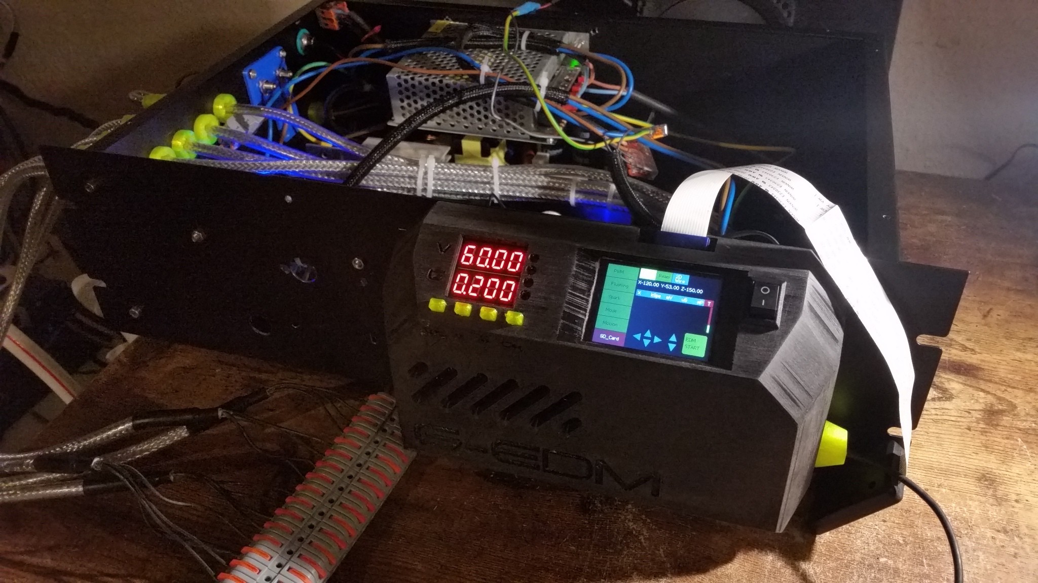
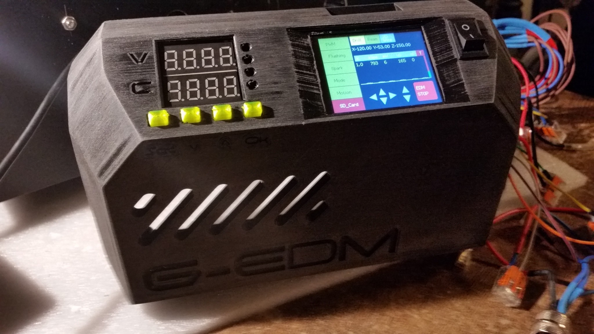
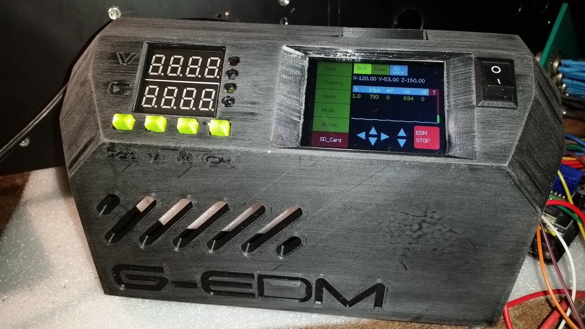
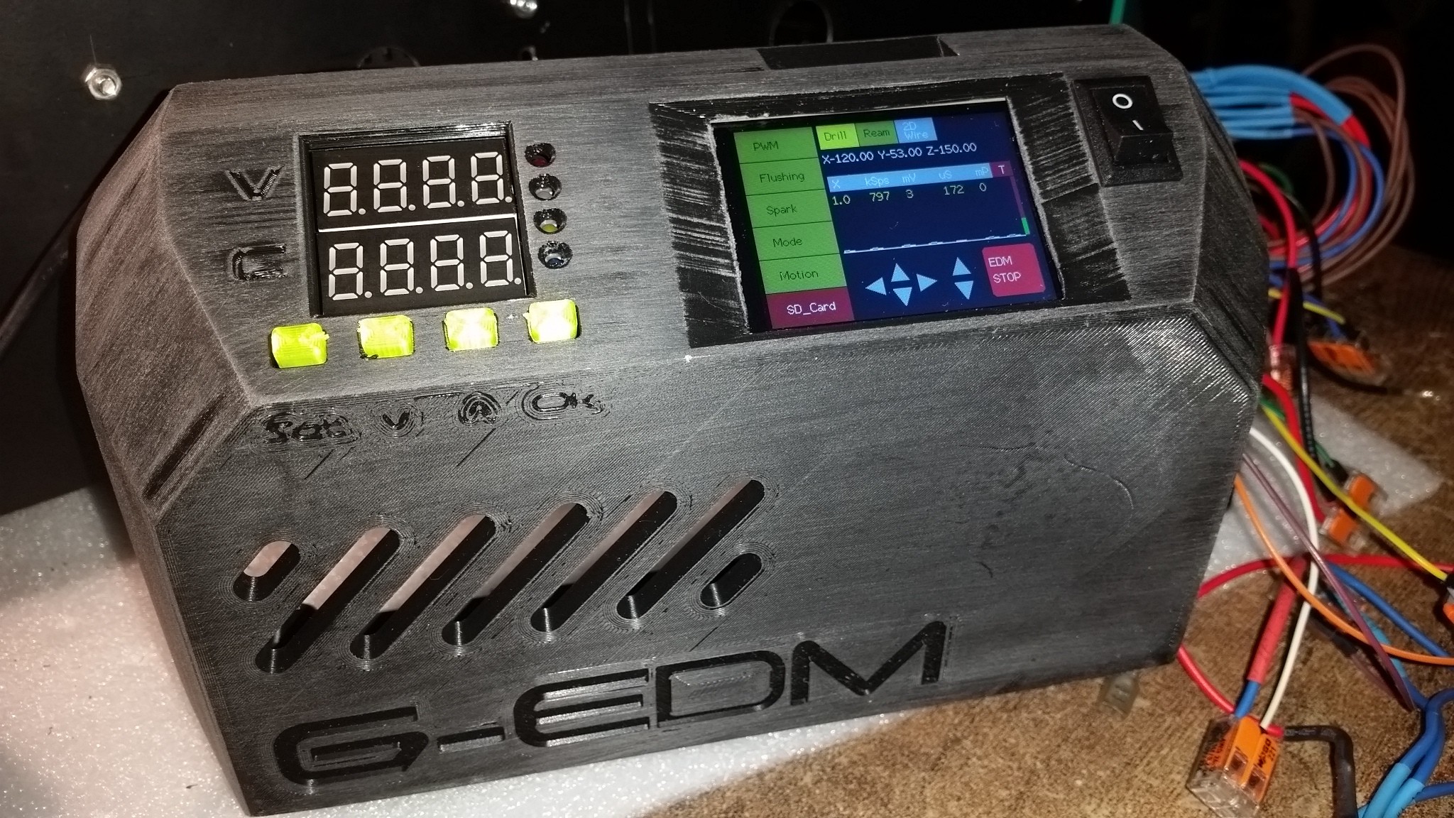
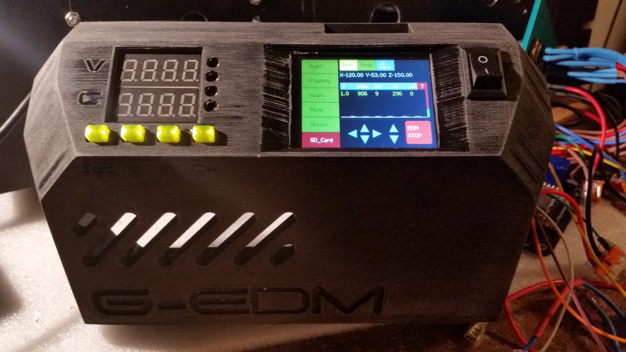
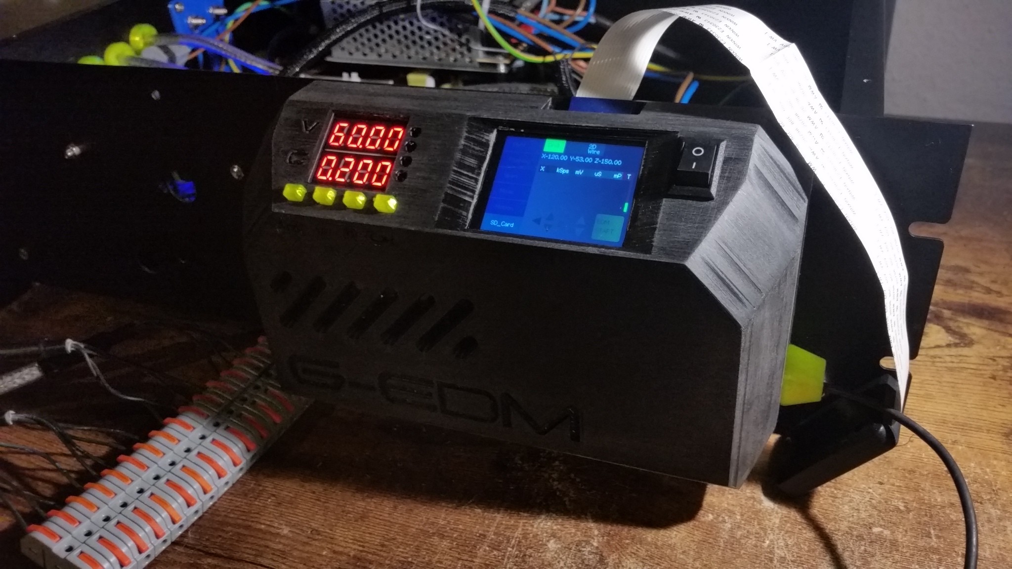
The final version of the control panel:


And more details:
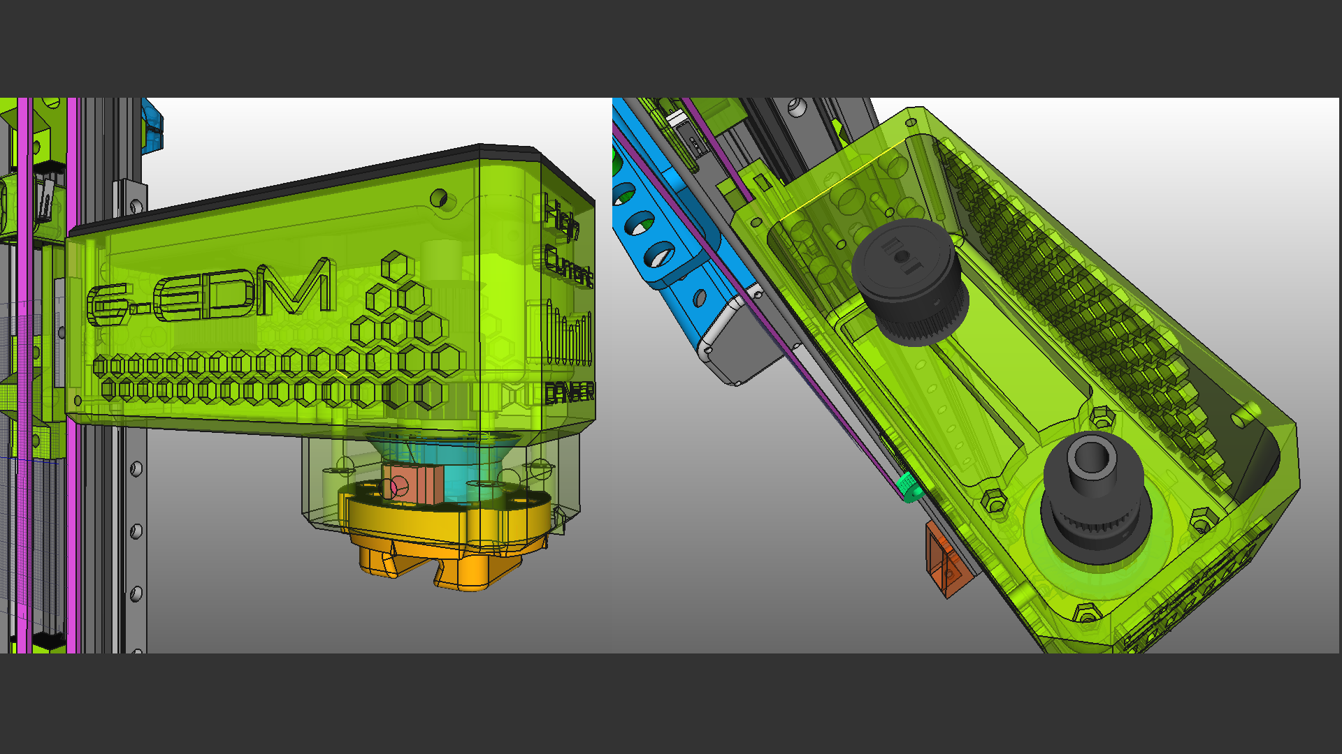

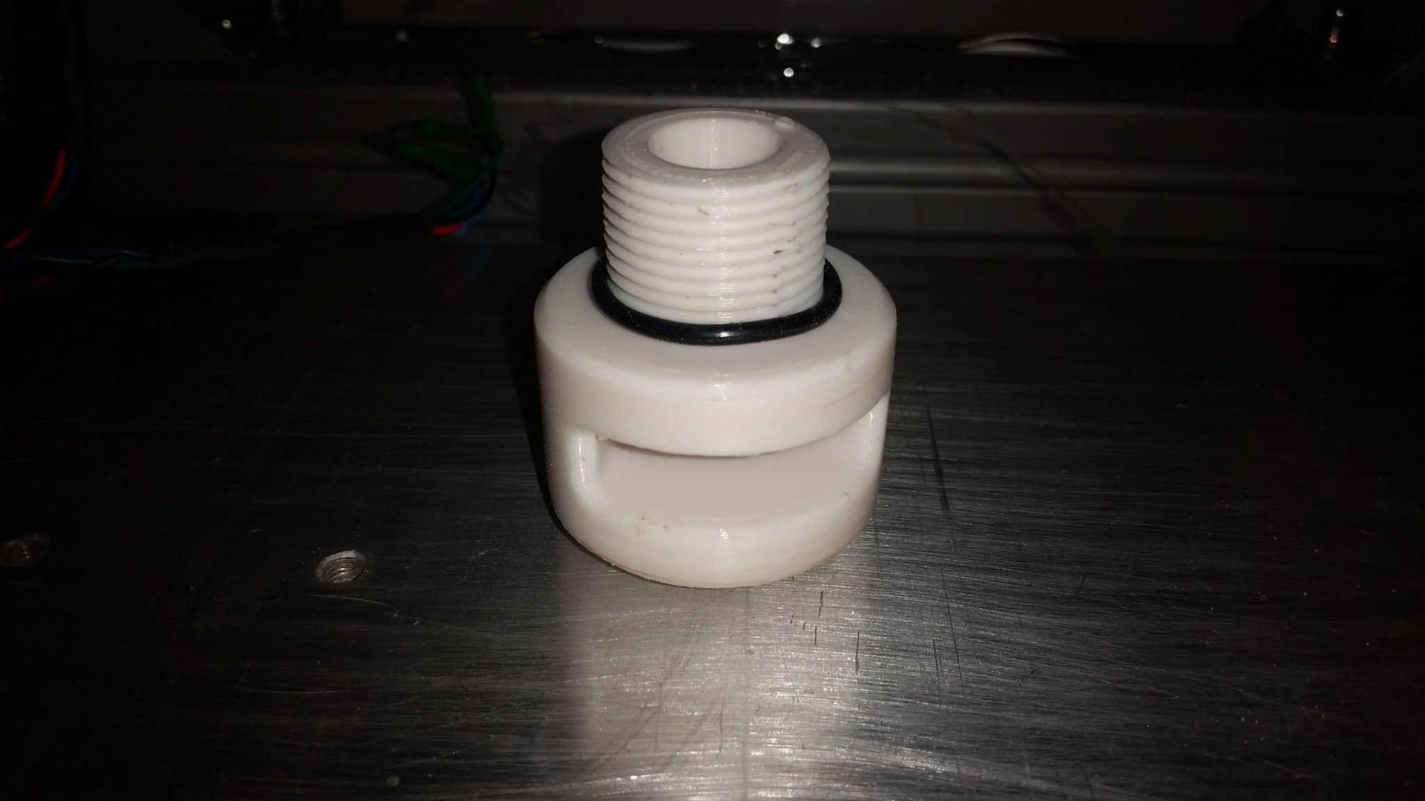
EDM can create a lot of EMI noise and therefore the spark generator needs to be in a shielded enclosure. But even the electrode and the spark itself create noise.

In the first builds the negative spark wire was mounted to the rotary drill chuck within the tool head. But this converted the electrode into a antenna with enough power to shut down the communication between the ESP and the display.

This highly depends on the Amps used, the duty cycle of the pulse and the length of the electrode but I decided to just connect the electrodes as close to the work piece as possible.

For round electrodes the blank wire is wrapped around them and for sheets alligator clips are good.

It doesn't look as good as the integrated contact but it reduces the noise a lot.

The pulse generator is a pretty basic and flexible concept that is easy to replicate. A 65v switching PSU is connected to a DPM8605 step down module that will provide 0-60v and 0-5A.

The output of the DPM8605 is then connected to the pulse generator PCB which is basically just a Mosfet gate driver, some capacitors and a voltage divider for the feedback signal.

This is the pulse generator PCB ( prototype ) wired up for some basic tests.

And this is the dual IRFP260N Mosfet PCB connected to the pulse generator PCB:

It is possible to use mostly any N-Channel Mosfet or even stack multiple Mosfet boards. I personally use a chunky single Hiperfet:

  • Pulseboard and motion controller from PCBway

    gedm-dev05/26/2023 at 03:00 0 comments

    PCBway delivered some boards for this project and what should I say except that they are awesome.

    I haven't expected this quality. The boards don't feel like the PCBs found in most products but more like Aluminum. They have a very nice finish and haptic.

    And the most important part: They work. :D

    Both boards are 4 layer PCBs with a ground plane and power planes.

    Big thanks to PCBway. They did a very good job.

    Let's take a look at the boards:

    And a look at the mostly finished boards. They are beautiful.

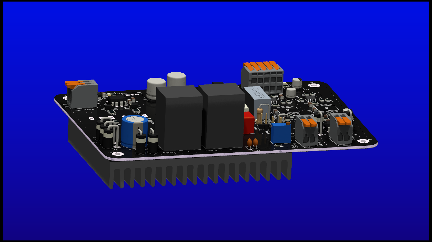
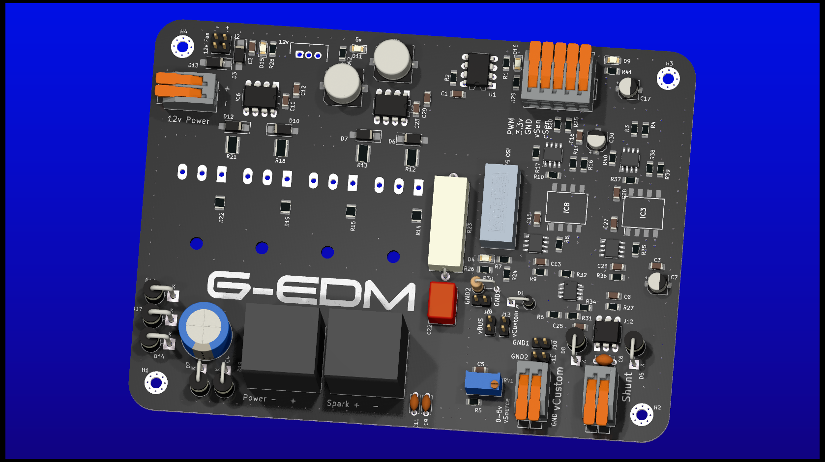
    This is the pulseboard. It is an improved version of the old prototype that comes with a high speed optocoupler to isolate the PWM signal and a trimmer poti to adjust the feedback voltage. It has a Zener diode for gate protection and one on the vSense feedback to protect the ESP.

    Tests showed that it delivers up to 100khz more or less reliable. 50khz works good. Above 50khz switching losses start. But at 50% duty cycle it delivers the 100khz. It is hard to debug without an oscilloscope. The multi-meter used is everything I have to measure the frequency and above 50khz it sometimes looses track of the frequency.

    I'm currently working on two other boards. All of them use different ways to get the sparks. One is a high side switch and one is again a low side switch with a discrete gate driver circuit and a pack of integrated mosfets on the PCB that will make the build process easier.

    The new motion controller is a beauty too. It reduces the number of PCBs in the controlbox from two to one. In the prototype the ESP32 breakoutboard was mounted below the motion controller. Both boards are now merged into one tiny 4 axis board that offers dip switches to set the microsteps for X,Y and the Spindle. Only Z uses software controlled microsteps. The ESP has no Pins left except one Input-only pin.

    The software changed heavily and the motion is now controlled with the fastaccel library that uses hardware generated step signals and can fire step pulses at 200khz.

    After testing all the connections on the soldered control board with a multimeter it was time to get the display running. Compared to the previous prototypes this was super easy.:

    And a little look at the x axis. It is already wired an running. Did some test with a 5kg load and the stepper had no problem at all to drive the axis at all possible microstep settings.

  • X axis is running

    gedm-dev05/19/2023 at 18:04 0 comments

    The X axis is finally running. The small Nema-17 Motor has enough power to drive the axis at all microstep settings. Pulleys and belt are printed.

    The ballscrew came without a nuthousing so I printed one. It is bigger and uses 4x pressed in M6 nuts to mount the table.

  • Four axis ESP32 Motion controller PCB

    gedm-dev05/14/2023 at 04:33 0 comments

    The ESP32 and the motionboards are now compacted onto one single 4 layer PCB.

    The board provides an output for a 12v fan and some dip switches to set the microsteps for XY and the spindle.

    Only the z-axis uses software controlled microstep settings. XY and the spindle use fixed microstepping.

    This should make the wiring a lot easier.

  • The new pulseboard

    gedm-dev05/11/2023 at 00:20 0 comments

    That was a hard ride. So much had to be learned in such a short time but there is light at the end of the road.

    The new pulseboard is mostly finished (some details are still missing like ground via stitching etc). It is a 4 layer PCB with power and ground planes.

    It has some pins to add fans and a trimmer poti to adjust the feedback voltage. A 3.3v zener diode protects the ESP pin from wrong settings at the poti.

    It is a high side gate driver that is rated for 200v max. With the adjustable feedback voltage the range of the voltages that can be used shifted dramatically. The PWM is isolated with a high speed optocoupler. ( The vSense feedback still isn't )

    The first voltage divider design used fixed resistor values and that limited the range to 30-60v. Now it can be 30-200v.

    Just a few weeks ago I had zero knowledge about PCBs at all and soldered some prototypes with wires and perfboards. At some point I got sick of it and tried to order the boards online. That wasn't as easy as thought. So much options and new technical terms. And the pricing was insane. I gave up on the idea until someone gave me a few sites that have a good name and are easier to use. I decided to give PCBway a try and the website helped me a lot to understand what gerber files are and what is needed to get a PCB. They also offered tutorials about how to create the files with kicad. Perfect.

    That's why I decided to pack the PCB files in the projects final release according to the requirements of this specific vendor. This decision was long ago. Now PCBway offered me free prototyping and I'm very glad about it.

    Big thanks to PCBway.

    Stay tuned:

  • The good ol' times and how everything started

    gedm-dev05/09/2023 at 20:36 0 comments

    This was the first concept and how everything started. One does never forget his first sparks.

    The Z axis still exists in the current model. It is just mounted to a bigger extrusion I had around from another project.

  • Final Axis design and a new pulseboard

    gedm-dev05/09/2023 at 01:28 0 comments

    The heart of the G-EDM will get a new design. After merging the 12v PSU into the spark generator it started to produce same heavy voltage drops on the feedback signal sometimes. So the grounding had some issues on the PCB.

    The new PCB will have a gnd plane concept with power and logic gnd merged at one point.. Also the mosfet will be switched in a high side configuration. Low side switching may produce oscillation and stuff that is not wanted after the noisy spark flushes to gnd through the mosfet.

    Had a hard time figuring out how to create a high speed, high current, high side N-Channel Mosfet switch. Bumpy ride from bootstrapping to charge pumps and level shifters.

    X axis is still printing but the first sidewall is ready. 20mm thick PLA+. Those things are massive.

    The CAD object:

  • XY axis and new tool head

    gedm-dev04/27/2023 at 02:25 0 comments

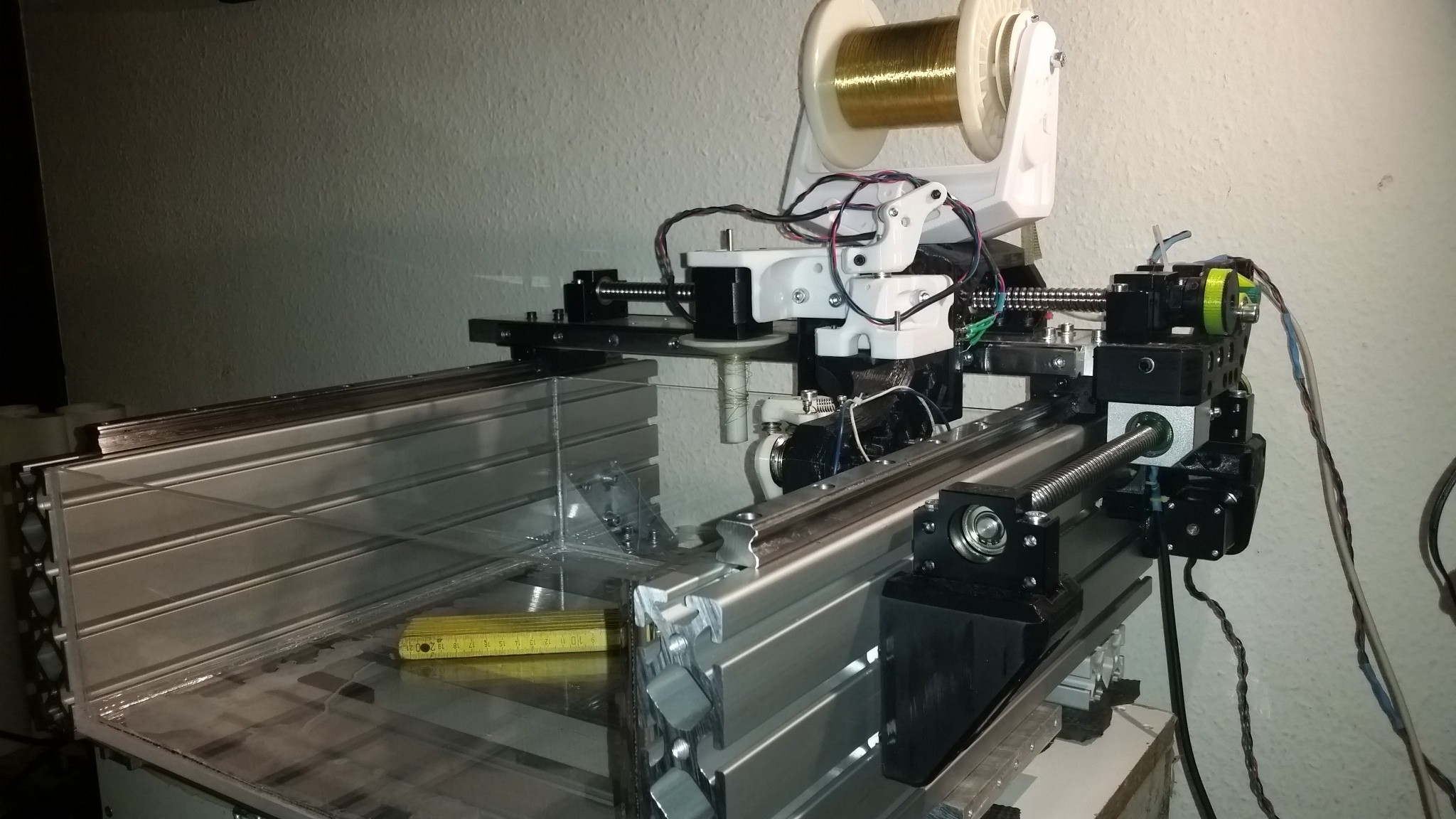
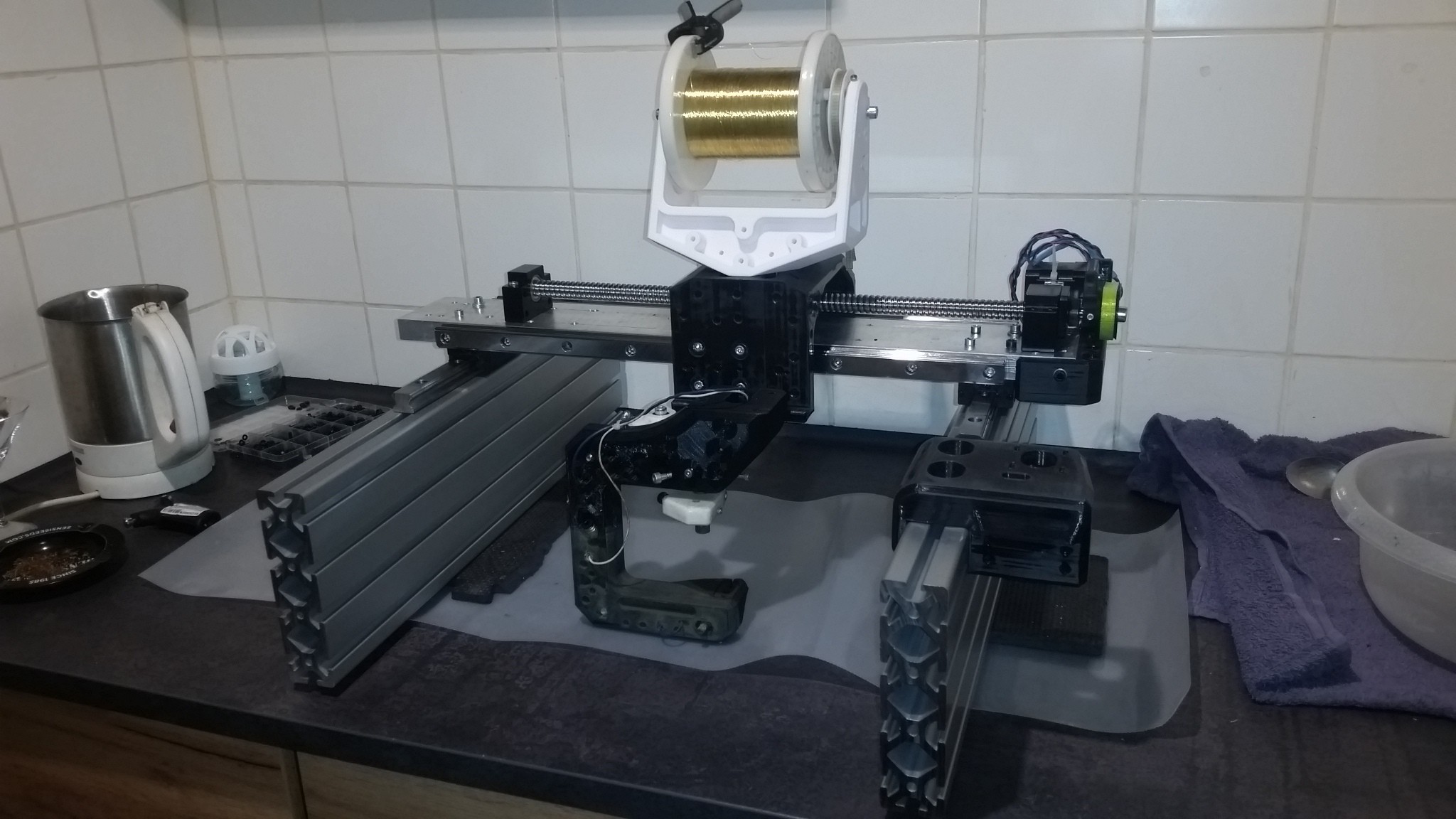
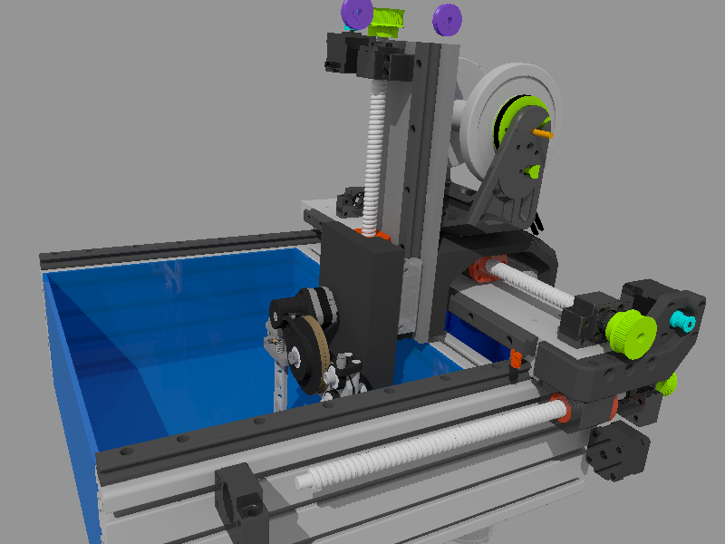
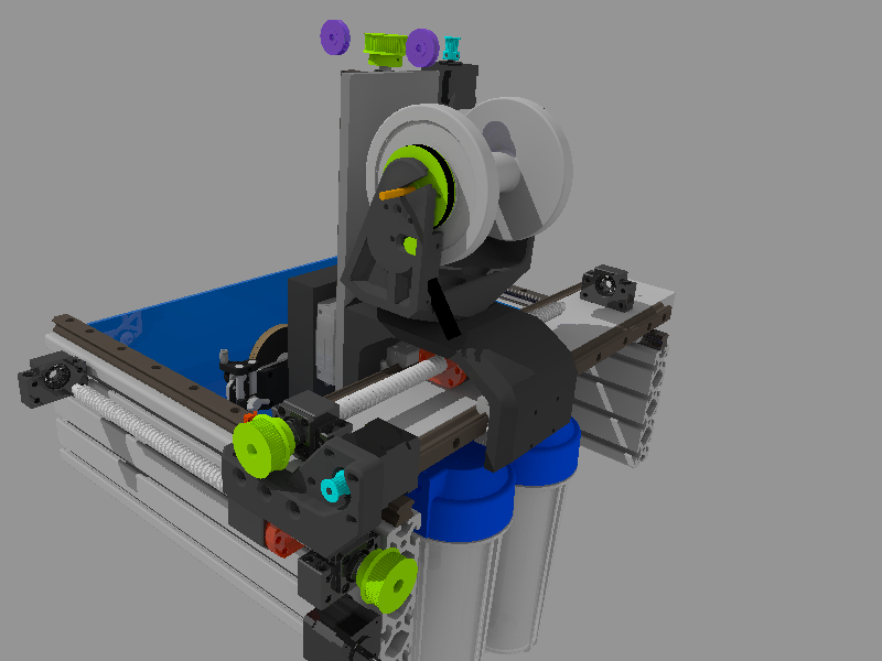
    The new HGR15 tool-head and the XY axis are mostly done.

    The new tool-head can take a Nema17 stepper and has an adapter to use a geared 12v DC motor.  Two ball bearings should make the spindle very rigid.

    A simple lever with ball-bearings is used as belt tensioner.

  • XY axis should be ready soon

    gedm-dev04/23/2023 at 01:28 0 comments

    The basic concept of the XY axis is ready and should be finished soon. The linear rail on the Z axis changed from a MGN12 to a HGR15. X and Y will use HGR20 rails.

    It will use SFU1605 Ballscrews to move X and Y.

    The most important part for me is getting everything ready for wire EDM and I already have some ideas for the design.

  • Building the new control panel

    gedm-dev04/22/2023 at 20:09 0 comments

    The new control panel is ready.

    It not just looks cleaner but also requires less external wiring. The stepper motors are powered from a simple adjustable 12v switching PSU that is now mounted inside the 19" spark generator enclosure.

    This timelapse video ( 4x speed) shows the wiring of the single axis sinker version.

  • First success with Armbian, NanoPi and ILI9341 Touch

    gedm-dev04/20/2023 at 20:35 1 comment

    After having a hard time getting the ILI9341 touchscreen working with the NanoPi Neo (Allwinner H3)  it seems to work now.

    To have more GPIOs available for other stuff the touch and display share one SPI bus.

    There is basically nothing available out of the box and I'm a total noob with NanoPi, Armbian and overlays so there may be errors.

    But it works.

    root@nanopineo:~# uname -a
    Linux nanopineo 5.15.93-sunxi #23.02.2 SMP Fri Feb 17 00:00:00 UTC 2023 armv7l armv7l armv7l GNU/Linux

    This is the wiring between ILI9341 and NanoPi Neo:

    /*
       3.3v <-->  VCC & LED
       GND  <-->  GND
       PC2  <-->  SCK       & T_CLK
       PC1  <-->  SDO<MISO> & T_DO
       PC0  <-->  SDI<MOSI> & T_DIN
       PA1  <-->  DC
       PG8  <-->  RESET
       PC3  <-->  CS
       PA3  <-->  T_CS
       PG9  <-->  T_IRG
     */

    This is the overlay ( ili9341-touch-double-spi-cs.dts ):

    /dts-v1/;
    /plugin/;
    
    / {
        compatible = "allwinner,sun8i-h3";
    
        fragment@0 {
            target = <&pio>;
            __overlay__ {
                spi0_cs1: spi0_cs1 {
                    pins = "PC3"; 
                    function = "gpio_out";
                    output-high;
                };
    
                spi1_cs1: spi1_cs1 {
                    pins = "PA3"; 
                    function = "gpio_out";
                    output-high;
                };
    
                opiz_display_pins: opiz_display_pins {
                    pins = "PA1", "PG8", "PA6";
                    function = "gpio_out";
                };
    
                ads7846_pins: ads7846_pins {
                    pins = "PG9";
                    function = "irq";
                };
    
    
            };
        };
    
        fragment@1 {
            target = <&spi1>;
            __overlay__ {
                pinctrl-names = "default", "default";
                pinctrl-1 = <&spi1_cs1>;
                cs-gpios = <0>, <&pio 0 3 0>; /* PA3 */
            };
        };
    
        fragment@2 {
            target = <&spi0>;
            __overlay__ {
                #address-cells = <1>;
                #size-cells = <0>;
                status = "okay";
    
                pinctrl-names = "default", "default";
                cs-gpios= <&pio 2 3 0>, <&pio 0 3 1>;
    
                opizdisplay: opiz-display@0 {
                    pinctrl-1 = <&spi0_cs1>;
                    reg = <0>; /* Chip Select 0 */
                    compatible = "ilitek,ili9341";
                    spi-max-frequency = <1000000>;
                    status = "okay";
                    pinctrl-names = "default";
                    pinctrl-0 = <&opiz_display_pins>;
                    rotate = <90>;
                    bgr = <0>;
                    fps = <33>;
                    buswidth = <8>;
                    dc-gpios = <&pio 0 1 0>;      /* PIN_22  GPIOA1 > */
                    reset-gpios = <&pio 6 8 1 >; /*    GPIOG8> */
                    /*led-gpios=<&pio 0 6 0>;        PIN_12  GPIOA6 > */
                    debug=<4>;                        
                };
    
                ads7846: ads7846@1 {
                    reg = <1>; /* Chip Select 1 */
                    compatible = "ti,ads7846";
                    spi-max-frequency = <1000000>;
                    status = "okay";
                    pinctrl-2=<&spi1_cs1 &spi1_cs1>;
                    pinctrl-names = "default";
                    pinctrl-3 = <&ads7846_pins>;
                    interrupt-parent = <&pio>;
                    interrupts = <6 9 2>; /* PG9 IRQ_TYPE_EDGE_FALLING */
                    pendown-gpio = <&pio 6 9 0>; /* PG9 */
                    /* driver defaults, optional */
                    ti,x-min = /bits/ 16 <0>;
                    ti,y-min = /bits/ 16 <0>;
                    ti,x-max = /bits/ 16 <0x0FFF>;
                    ti,y-max = /bits/ 16 <0x0FFF>;
                    ti,pressure-min = /bits/ 16 <0>;
                    ti,pressure-max = /bits/ 16 <0xFFFF>;
                    ti,x-plate-ohms = /bits/ 16 <400>;
                };
    
            };
    
        };
    

    This is the /boot/armbianEnv.txt

    verbosity=1
    bootlogo=false
    console=serial
    disp_mode=1920x1080p60
    overlay_prefix=sun8i-h3
    overlays=usbhost1 usbhost2 spi0
    param_spidev_spi_bus=0
    param_spidev_spi_cs=1
    param_spidev_spi_cs=0
    rootdev=UUID=XYZ-LONG-UUID-IS-LONG
    rootfstype=ext4
    user_overlays=ili9341-touch-double-spi-cs
    usbstoragequirks=0x2537:0x1066:u,0x2537:0x1068:u

    After connecting via ssh and starting evtest it shows this when touched ( not sure if it shows the correct coordinates yet )

    Event: time 1682020476.763295, -------------- SYN_REPORT ------------
    Event: time 1682020476.775286, type 3 (EV_ABS), code 0 (ABS_X), value 535
    Event: time 1682020476.775286, type 3 (EV_ABS), code 1 (ABS_Y), value 3553
    Event: time 1682020476.775286, type 3 (EV_ABS), code 24 (ABS_PRESSURE), value 65169

    To add the overlay:

    armbian-add-overlay /path/to/ili9341-touch-double-spi-cs.dts

    I'm still not sure if it works like it should. But at least it does something that looks promising.

View all 12 project logs

Enjoy this project?

Share

Discussions

Similar Projects

Does this project spark your interest?

Become a member to follow this project and never miss any updates