Close
0%
0%

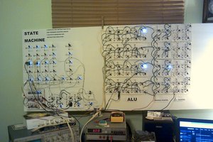
GLASNOST Vacuum Tube Computer

A vacuum tube computer without semiconductors,
4-bit Von Neumann, 4096 words core memory, graphics output

Similar projects worth following
The goal is to build a computer consisting only of vacuum tubes and passive components like resistors, capacitors and ferrites - no semiconductors. It´s a long term project.
The machine will have a graphical display (oscilloscope) and 4096 words of RAM (4-bit each).
It´s a custom 4-bit architecture based on NOT / NOR / OR gates, built from surplus Russian tubes.
The name GLASNOST stands for "GLAS, NO SEMICONDUCTORS".
It uses a 4-bit Von Neumann architecture and can address 4096 words of 4-bit each from magnetic core memory. Voltage levels must be safe to touch, so I will use 48V+ and 16V- only.

It´s a solo project, just to get my head free from the dayjob.
The reason it´s solo is to avoid pressure, sync-ups and deadlines,
basically using it as escapism without having any obligations.

  • choosing core memory

    Paul Kocyla07/14/2023 at 09:56 0 comments

    Got a few of those core memories from a Russian PDP-8 clone, the Saratov-2, it´s 64x64 core matrix, forming 4096 bits.
    I´d need four of those planes for the computer, one plane for each bit of the 4-bit word. The thing is that they are only addressable by 64x64 lines, so they would need 128 line drivers. And there is only one inhibit wire that can disable the whole matrix, so I can´t subdivide the matrix.
    It makes sense when you use ICs or transistors that drive such a big matrix, but addressing all 64 lines and 64 columns with tubes would be just insane.
    I am thinking of either weave the core memory myself or to at least weave more inhibit wires into the existing ones; four inhibit lines, each for one of the four quadrants.
    In that case, I could use just 2*32 line drivers (+4 inhibit drivers) instead of 2*64 - each driver consisting of several tubes.
    Or I could use 16 inhibit lines and only 2*16 line drivers, dunno yet.
    The current needed for flipping the core is around 500mA, so 250mA per X/Y line. I´ll use transformers to get the 20mA current of the tubes up to 250mA, I need to wire the transformers manually. Another reason to reduce the driver count.
    I´ll try to modify the existing modules, let´s see how hard this turns out to be :-D. I got a microscope, and I did SMD for decades, so it should work out fine. Some task for the upcoming weekend...


    Ist möglicherweise ein Bild von Text

  • Logic finished

    Paul Kocyla07/13/2023 at 08:08 0 comments

    I finished the logic for the computer after countless weekends and decided to finally submit this project.
    The computer is now running in LOGISIM (a logic simulator).
    I already prototyped the logic gates and tested them up to a 5 MHz clock. I got inverters as well as NOR / OR gates to work at accurate speeds, so those are the gates I´ll stick with for the complete build. The logic diagram consists solely of those three gates. I´ll explain the building blocks in separate videos.

View all 2 project logs

Enjoy this project?

Share

Discussions

Lee Hart wrote 07/19/2023 at 18:03 point

Core memory is reasonably low power; but takes high current at low voltage due to each core having 1-turn coils. High currents are not suitable for vacuum tubes, but gas discharge tubes can do it (neon lamps, flash tubes, etc.) So perhaps something like a neon lamp relaxation oscillator can generate a high enough current pulse to X-Y select the cores. I suspect it will take something bigger than an NE-2 to get a high enough peak current, though.

  Are you sure? yes | no

Paul Kocyla wrote 07/20/2023 at 08:32 point

Neon tubes are too slow, you wouldn´t get more than 10kHz out of them.
I´ve done a tube synthesizer with them before, they are really only suitable for low frequencies - although they have nice side effects when pushing beyond the limits :)
I will wind pulse transformers to drive the memory instead.
Coincidently, there is one paper from the 50ies that refers to that problem and proposes the same solution. I dunno if it has ever been tried, though.
Power tubes "always" existed, and money was not the problem when building those computers. Winding transformers would have been probably more costly than buying off-the-shelf tubes back than.
My only concern is the loss of bandwidth in the transformers. I will perform the experiments maybe next weekend, when time allows.
I´ll use a similar setup that CuriousMarc had in his videos, having two pulse generators and a power supply amplifier. I´ll check the transformer solution with that before proceeding with a final tube driver circuit.
Ramping of the pulses is extremely important to avoid multiple signals on the sense wire.
X has to come up first, then Y (or vice versa) with relatively soft slopes.
I´ll figure out the optimal timings with the lab setup and will tune the tube circuit with delay lines and grid resistors to produce similar pulse shapes.
The transformer cores already arrived, I got some from AliExpress in two different sizes.
The tubes are rated for 15mA continuous current at 200V. As I´m using 48V, the tube limits out at 20mA anyways, ca. 12mA when it´s tuned to the sweet spot.
The transformer will have a ratio of 1:15 or 1:20 - that´s why I have concerns to achieve a bandwidth of 1MHz - but we´ll see in a couple of days.
If it doesn´t work, I´ll use power tubes for the driving stage to either reduce transformer windings or get rid of the transformers at all. The problem is the price of power tubes. They would cost 10-20x as much as the ones I got. I mean, the reason I´m building up this beast is the low cost of the tubes. I got them for 10% of the market price. I assume they come either from Russia or from Ukraine. Someone needed to get rid of new old stock. Despite beeing bought from a reseller, they are still cheap enough to make the project possible.

  Are you sure? yes | no

Lee Hart wrote 07/20/2023 at 16:42 point

Paul, what about a small thyratron, like the 2D21? Datasheet is at tube-data.com/sheets/137/2/2D21.pdf. It switches on in 0.5uSec, off in 35uSec, has a peak current of 500ma and continuous average current of 100mA. Finding a few is easy, though finding a quantity of them would be difficult.

There are (or were) quite a few other gas trigger tube. Some are quite small; like a neon lamp with a 3rd control grid. I'm not sure which ones you can still find. Some of them were used in street lamp "starter" circuits, which were produced by the millions.

On transformers: You should have no trouble operating them at as high a frequency as you need. With the right core and winding technique, they work well into the UHF range!

Happy hacking! :-)

  Are you sure? yes | no

Paul Kocyla wrote 07/21/2023 at 06:18 point

Thanx for the info on the 2D21. Switch time of 35µs is too slow, so I´ll probably stick with the transformers. But it might come handy for peripherals, like driving a loudspeaker or lamps.

  Are you sure? yes | no

PostalPreacher wrote 07/17/2023 at 23:32 point

"without having any obligations." The only way to enjoy a project.

  Are you sure? yes | no

Paul Kocyla wrote 07/17/2023 at 06:06 point

It will be 1400-2000 tubes, depends if I can optimize a few more things.
I got them for dirt cheap, that´s why I decided to make a "big" computer. It will still be pricey, though. But it´s a 1-2 years project, so the budget can be stretched.
Each tube has a heat dissipation of 2W and will drive up to 1W max, less in average.

The building blocks will go into 19" racks, each one actively cooled. Got the racks already.
The project design is ongoing for two months now, but it was not ready for publishing until now.

I finished experiments with logic gates and got them working properly up to 5 MHz @ 48V after some tuning. Will make a video when assembling some bigger building blocks. There are cheap but powerful supplies available. The supplies of course have semiconductors in them, but I´ll make that compromise for now. They can still be replaced later with linear transformers.
The bottleneck for speed is the core memory and the gate propagation depth. To reliably use it, the clock frequency will be around 500kHz. The propagation time on falling edge might be significantly shorter, so I could speed it up by changing the duty cycle of the clock.

  Are you sure? yes | no

Peabody1929 wrote 07/16/2023 at 23:18 point

Do you have an estimate of the number of tubes required, the power to run them and the required cooling?

  Are you sure? yes | no

Similar Projects

Does this project spark your interest?

Become a member to follow this project and never miss any updates