Background
This project was inspired by Ken Shirriff's blog post reverse engineering a Sperry Mach Airspeed indicator. After purchasing my own and finding the units power supply non-functional, rather than repair the power supply I opted to take advantage of the modular design to replace the rear half of the unit (the electronics bay) with my own design which rather than taking external input generated its own random movements for the sake of being desk art of sorts.
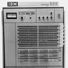
My unit was manufactured April 4th 1979 by Sperry Rand Corporation of Phoenix Arizona. With a weight of 2.8 lbs, the unit takes analog voltage inputs from an air data computer which it then uses in a DC servo loop to control the position of three primary indicators:
1. Airspeed is indicated by the white hand, this model supports 60-450 knots
2. Maximum airspeed is indicated by the white/orange hand
3. Mach number is indicated by a rotating dial indicator
All three rely on the same configuration of DC motors and coupled feedback potentiometers.
In addition to the three primary indicators, a lamp bulb lights up the face with a warm incandescent glow and a three position indicator shows the status of the system being either off (default position guaranteed by spring returns), a blank indicator (indicating on), or VMO which indicates overspeed warning.


The original design uses a clever flex pcb backplane with two "cards" populated and one slot unpopulated. Multiple test points are accessible on the rear of the unit once the shroud is removed.
A New Lease on Life
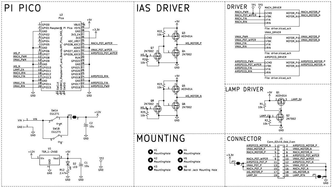
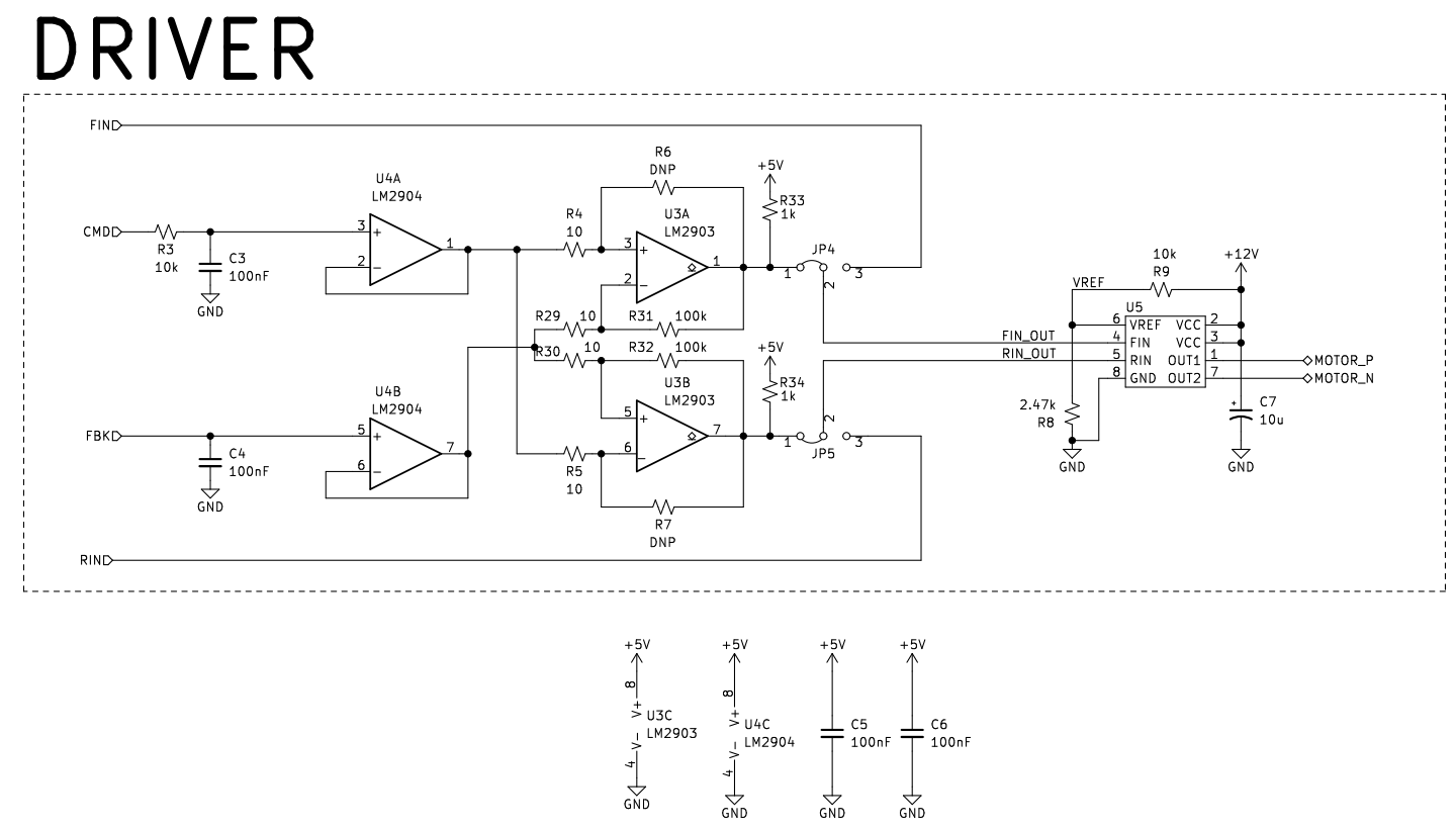
By removing the original electronics, nearly half the length of the unit can be replaced. The new electronics rely on a Raspberry Pi Pico which whirrs the various dials and gauges to new positions several times a minute. Power is supplied from a 12V barrel jack on the rear and requires no more than 0.5A to actuate all actuators and lights at once. A 5V DC:DC module provides power for the lamp as well as the Raspberry Pi. The Pi uses its PWM peripherals and RC low pass filters to generate an analog voltage for the BD6221F DC servo controller ICs to use.
Since the new packaging was nearly half the length, it didn't make much sense to use the original shroud. Instead I 3D printed a new shroud which includes cutouts in the rear to support the new PCB as well featuring a window in the top face where an acrylic sheet provides a view of the various motors, gears, and dials as they whirr away.
The modular nature of the original design allowed me to retain all the original parts such that it could be returned to its original state while giving it a new lease on life.
 vlk
vlk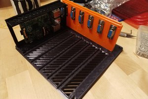
 Dave Pedu
 Tyler Ward (Scorpia)
 Jarred
Consider your lifestyle and any potential future changes when selecting furniture. If you have kids or pets, for example, choose fabrics that are easy to clean and maintain.[url=https://heavenfurniture.ae/]Furniture[/url]