 Brent w
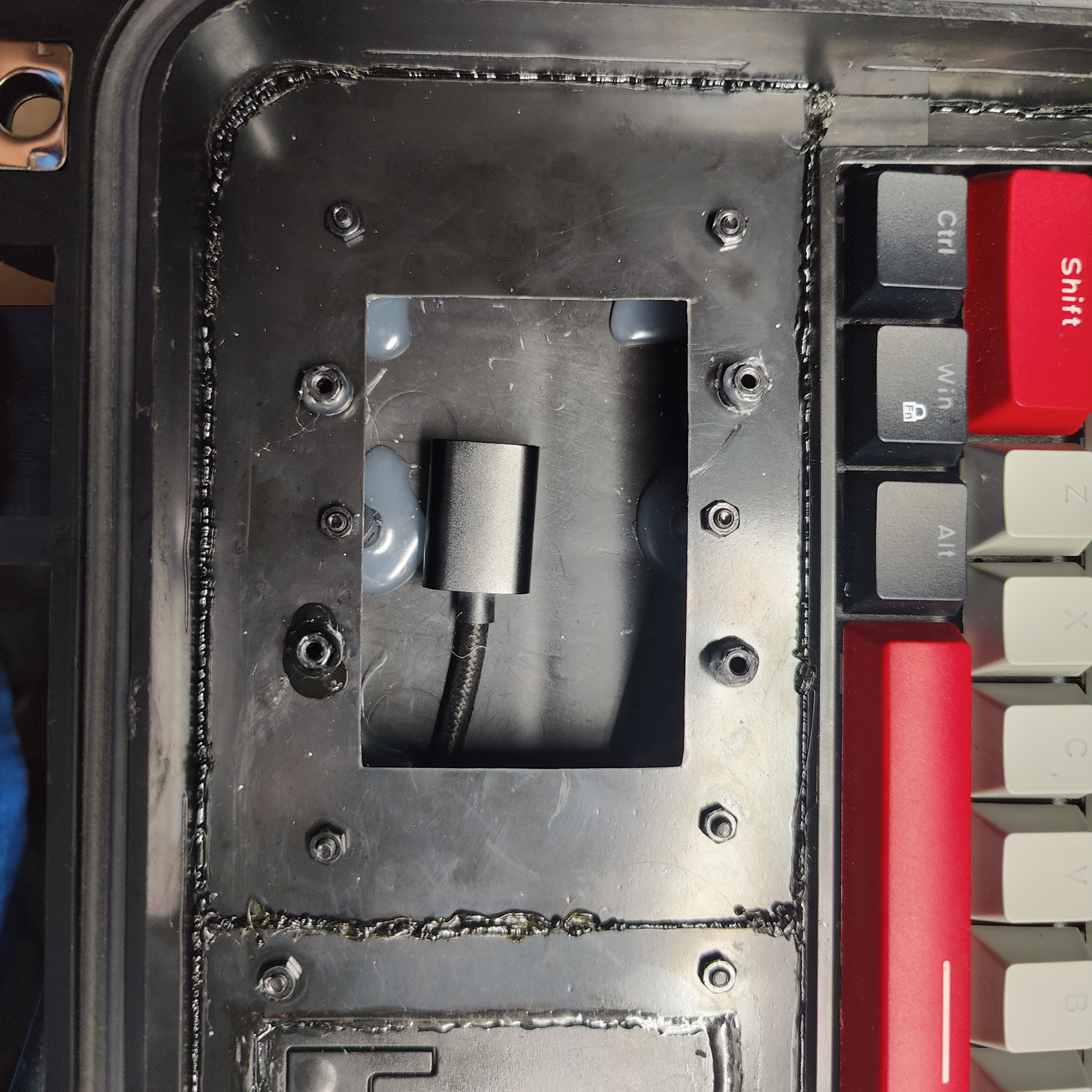
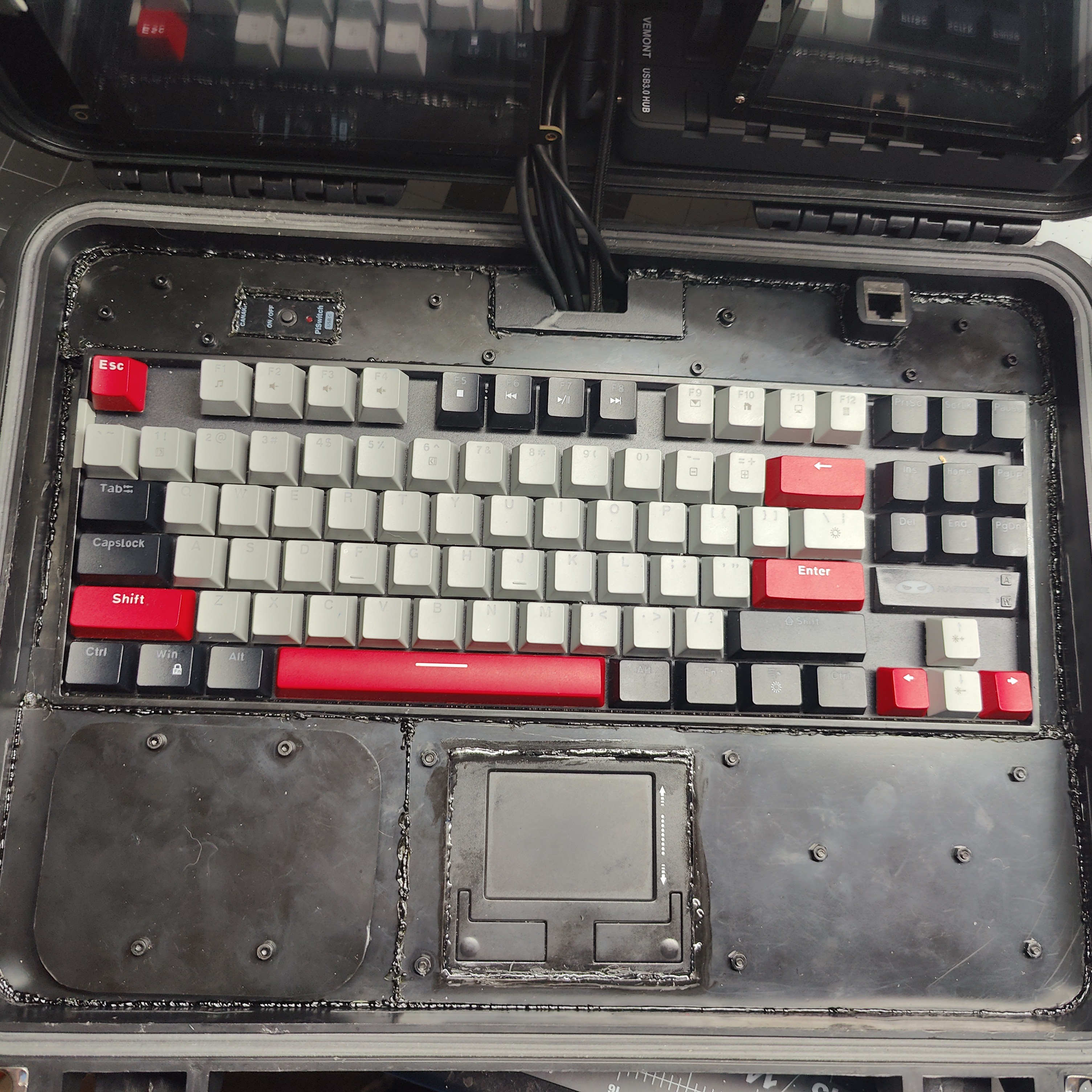
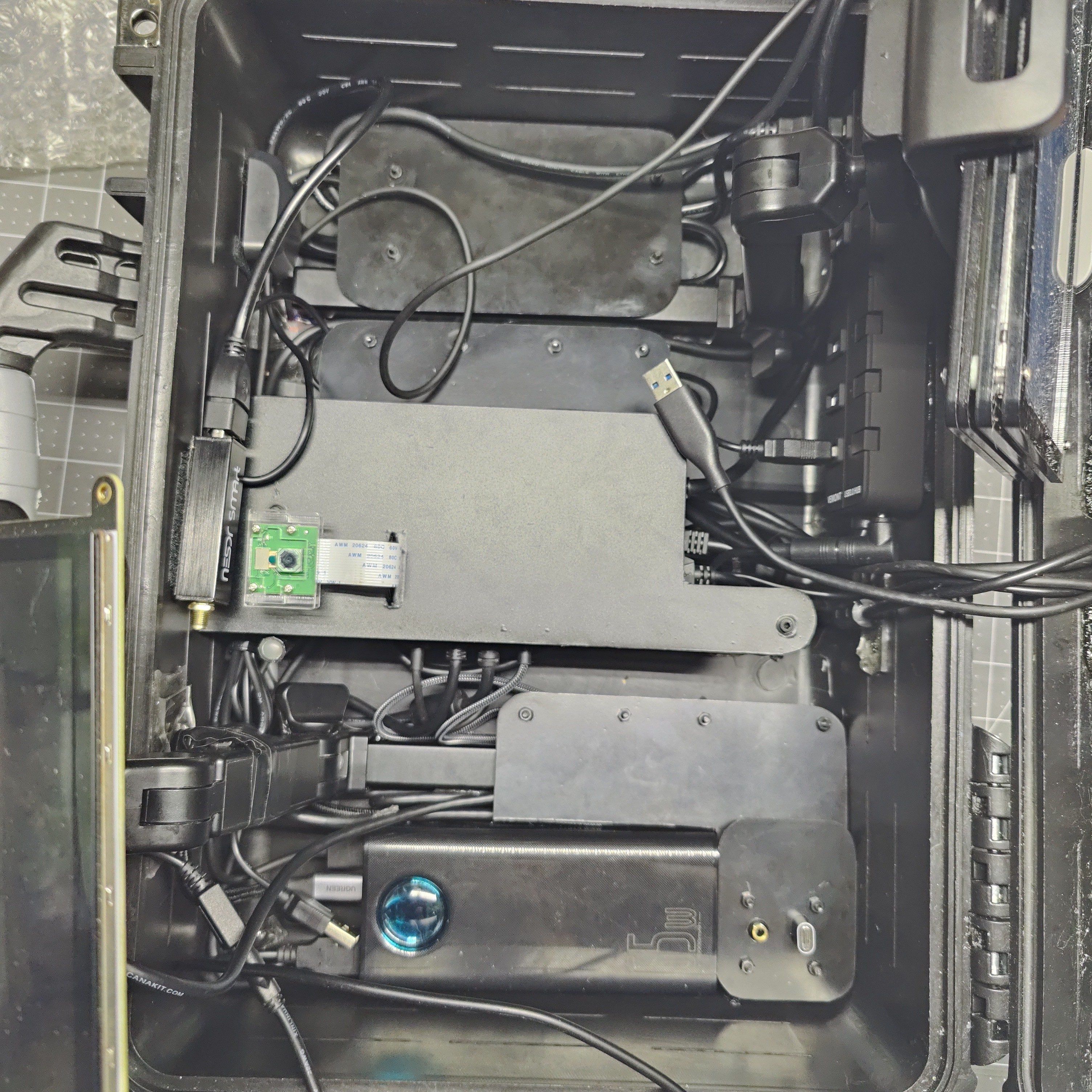
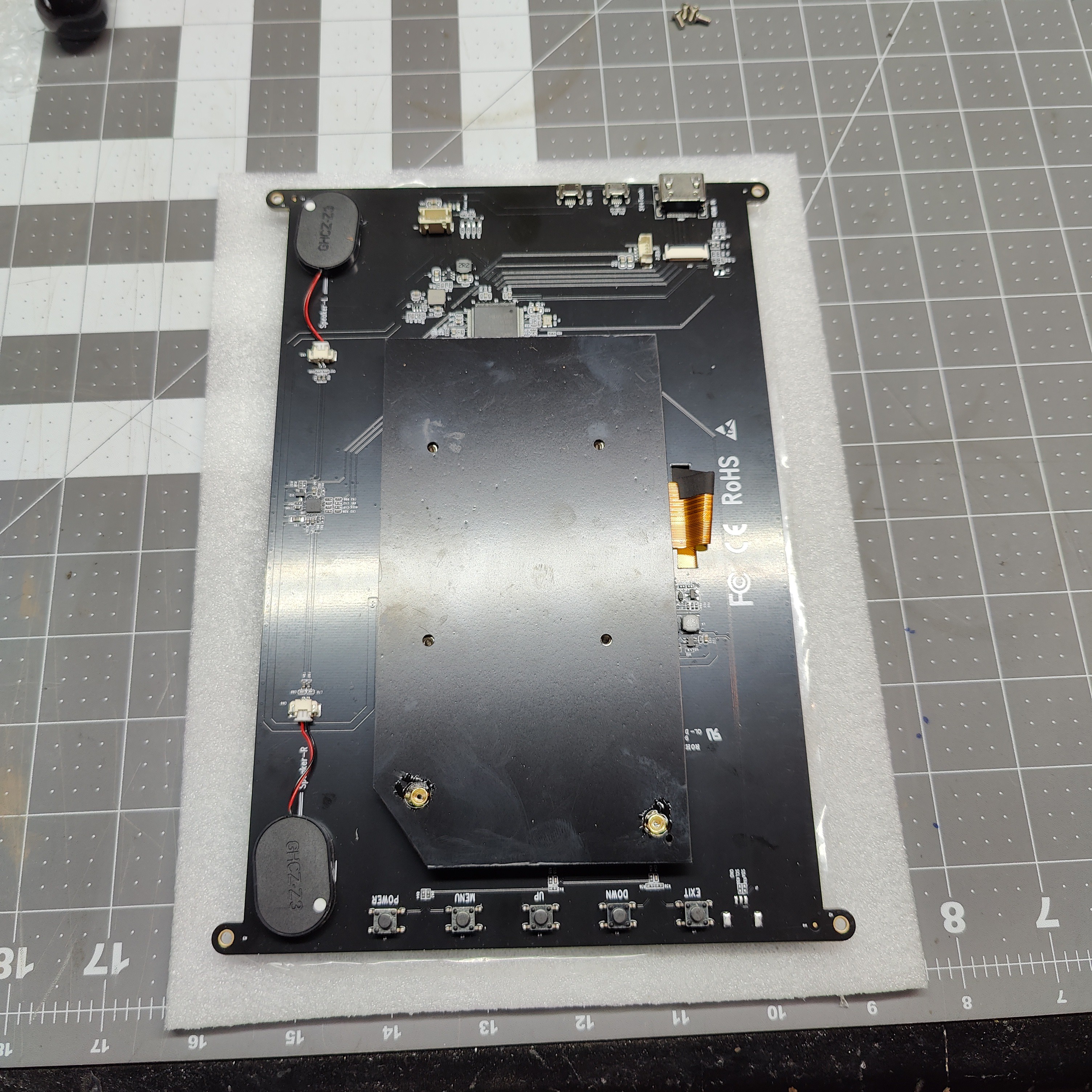
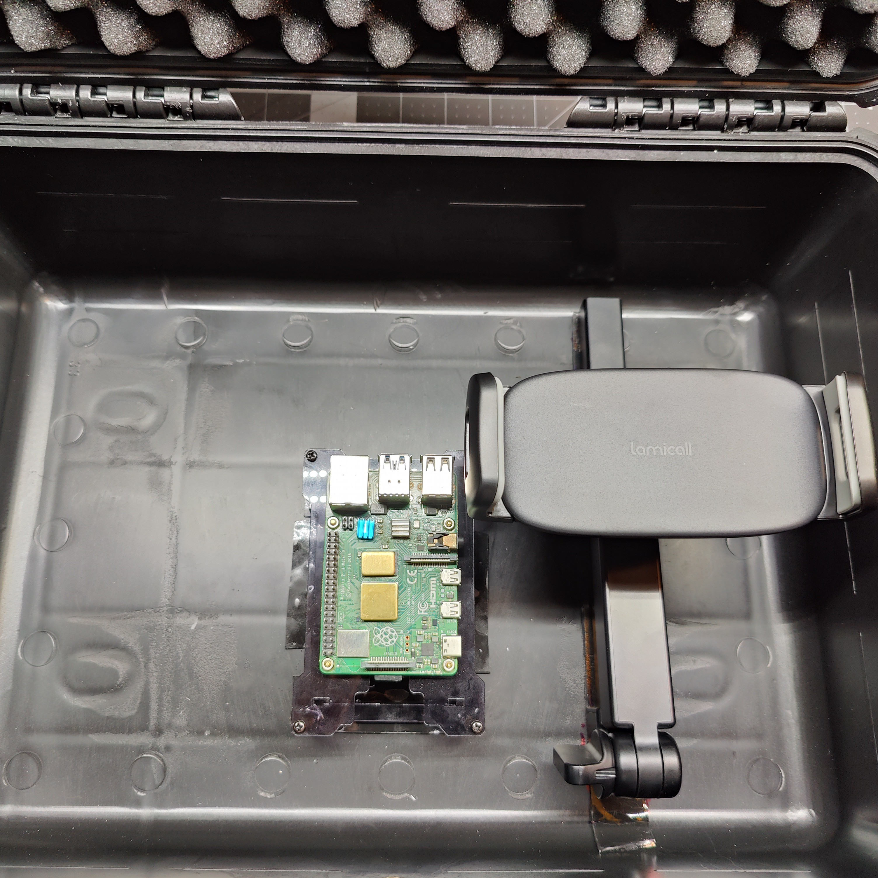
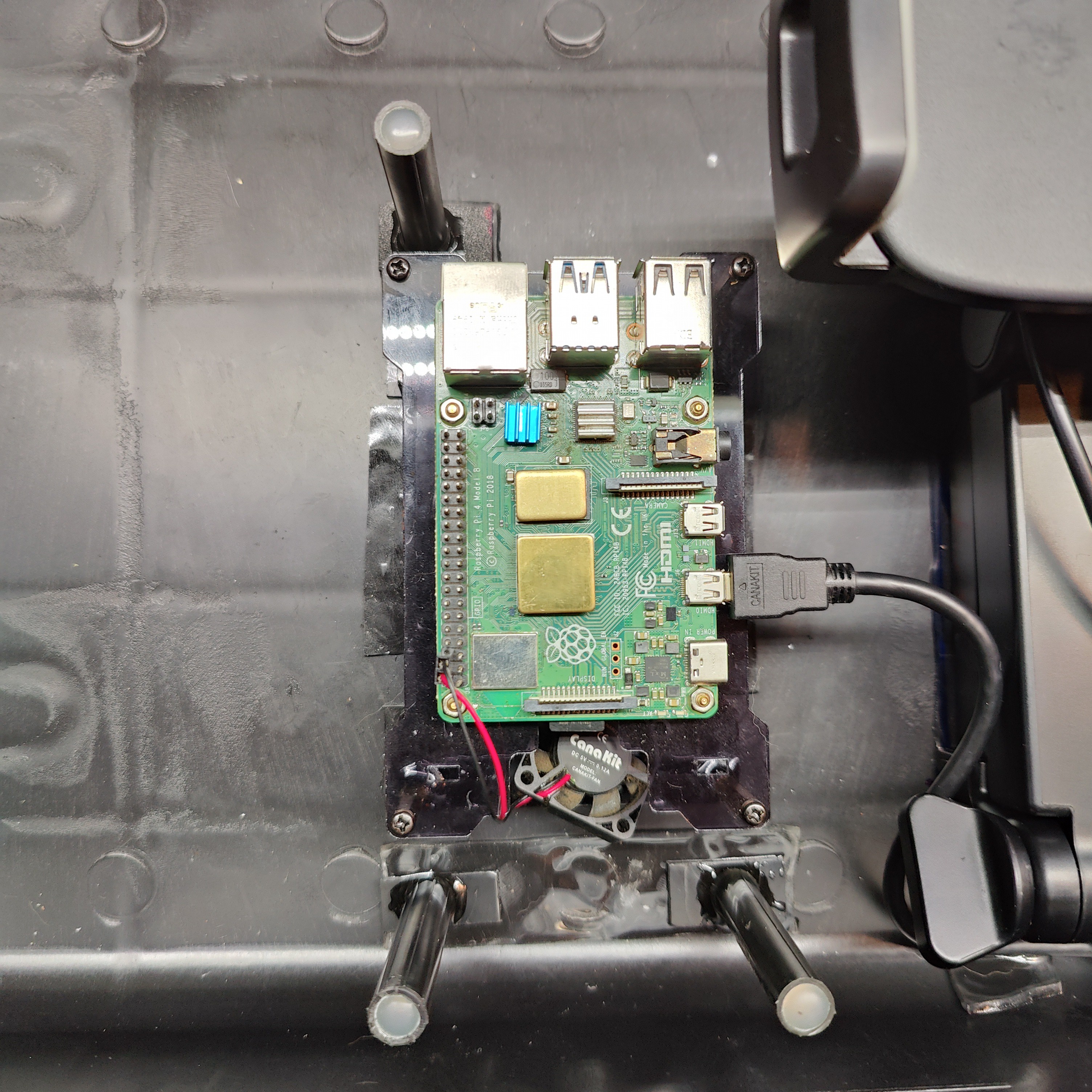
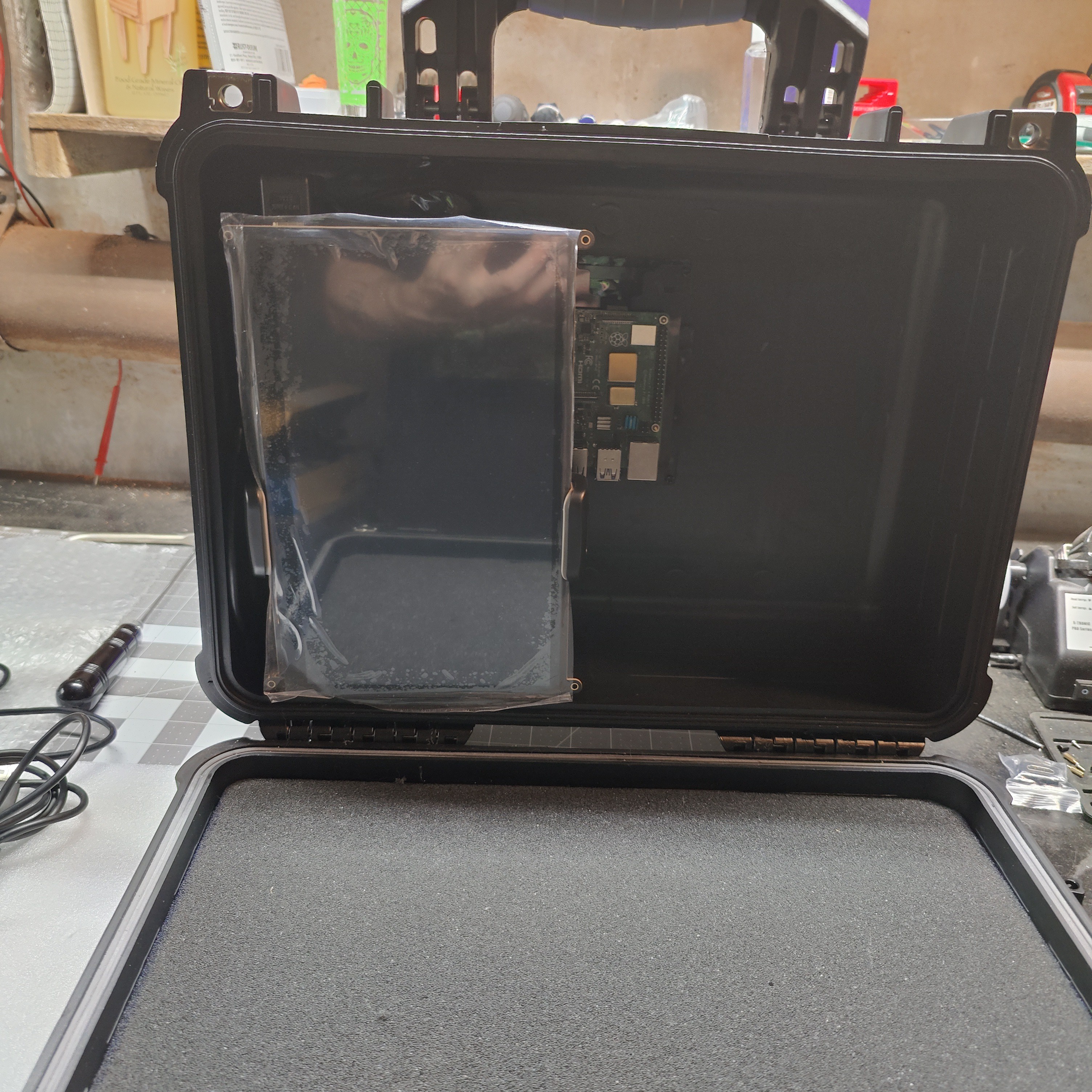
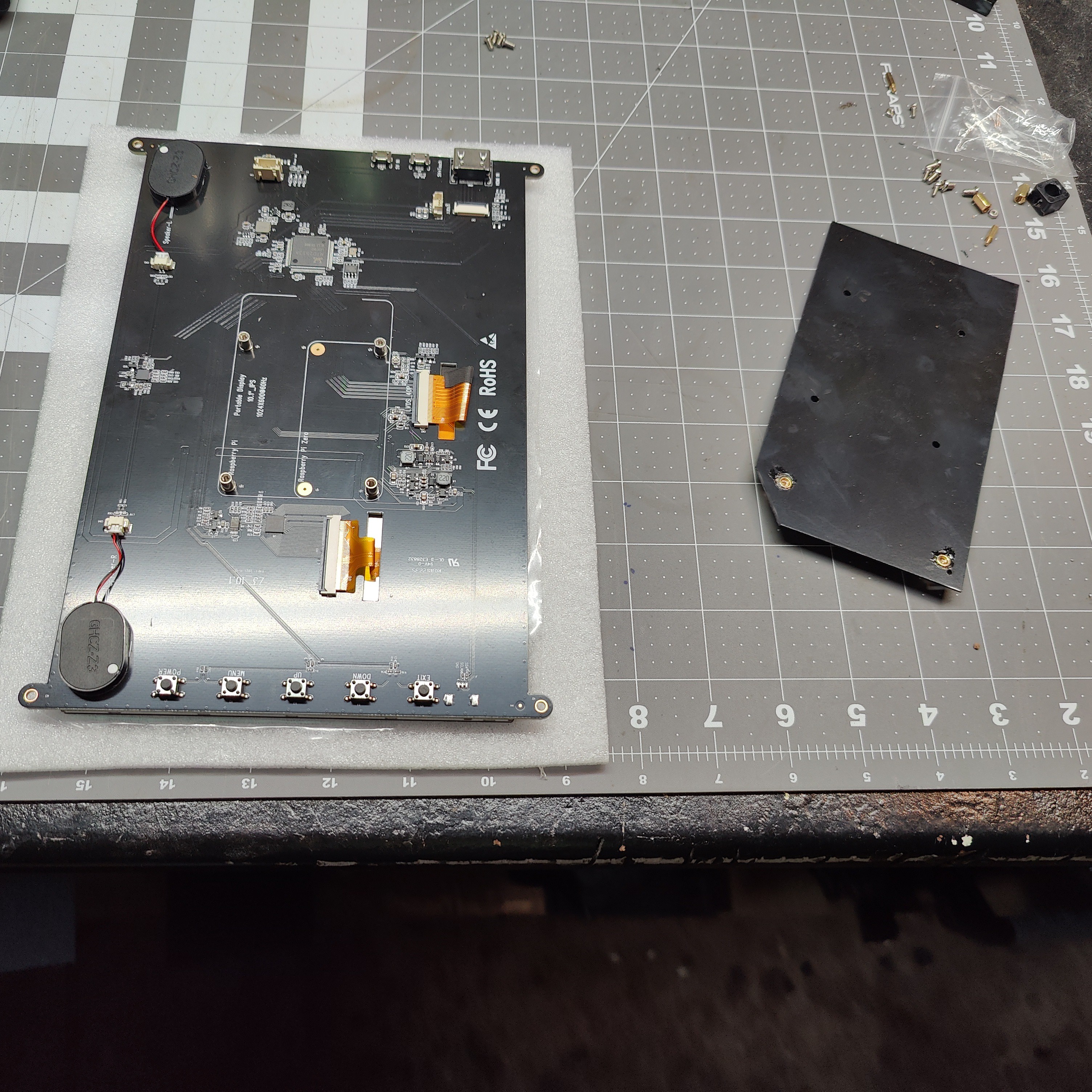
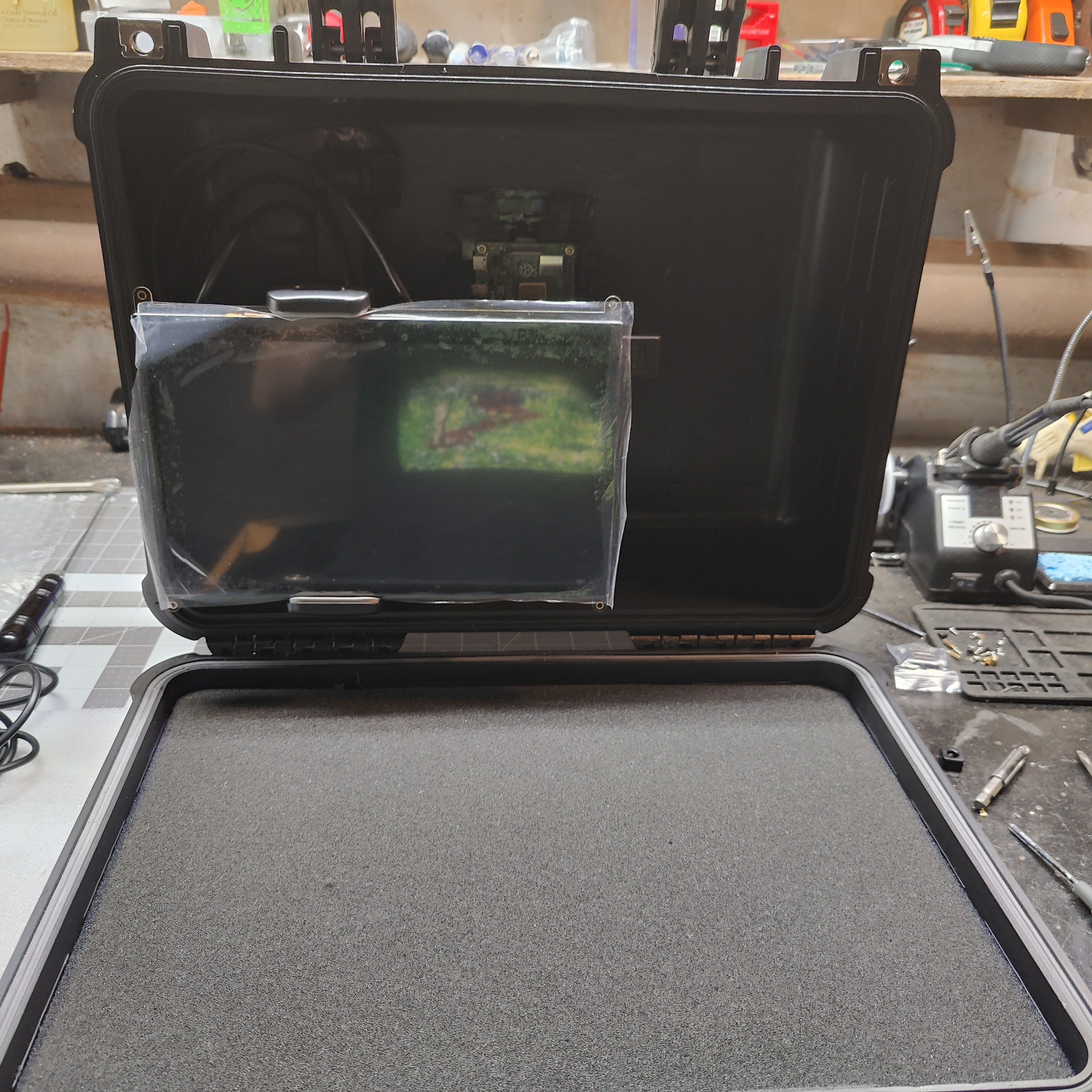
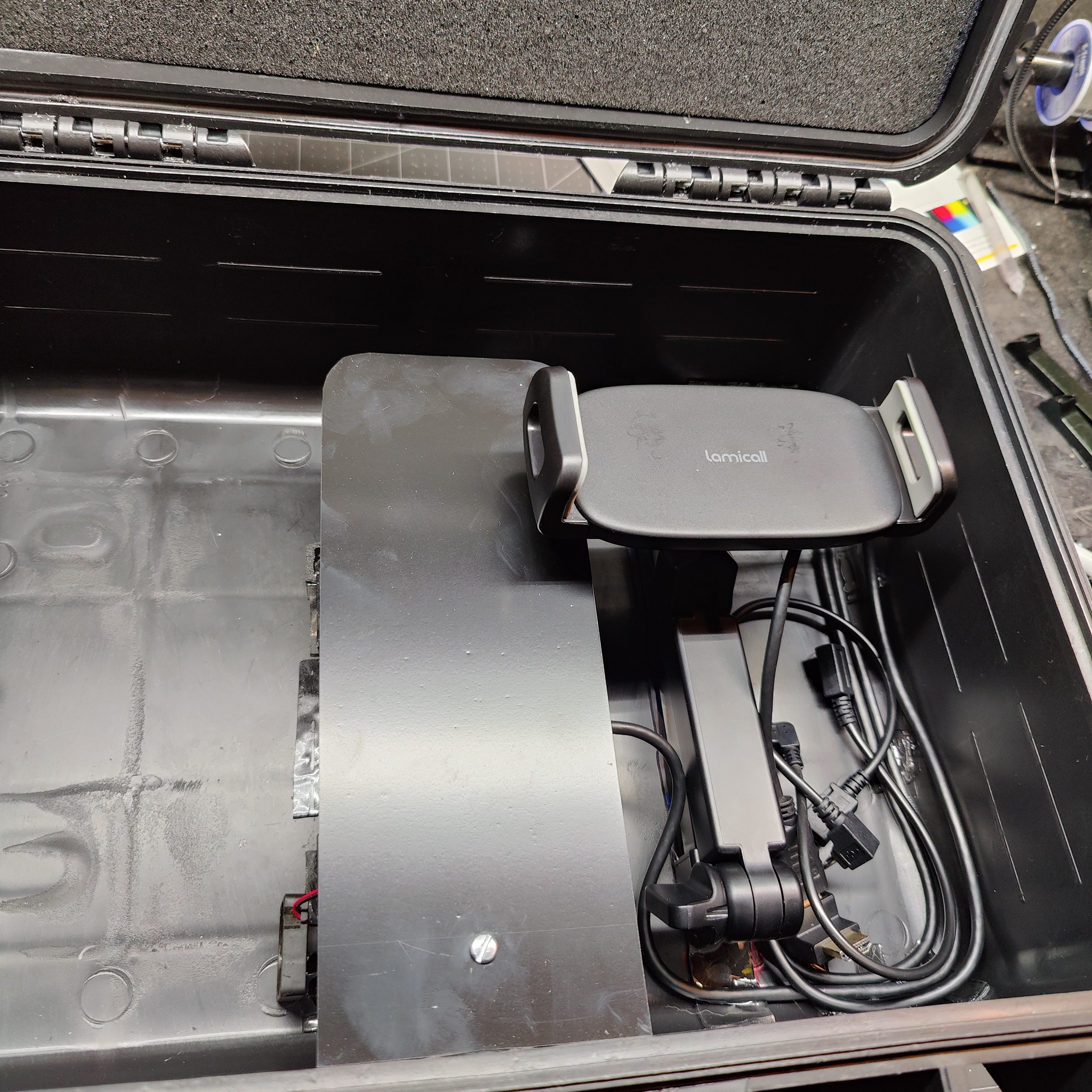
This cyberdeck falls into the "hacker // prepper" category. It can be used as a daily driver but is intended for a survivalist situation. For this reason I made sure to include GPS and RTL-SDR dongles in my build. I also wanted to have two screens on articulating stands so they can be adjusted. You can play media , transport and read books, navigate and communicate. I also have a few hacking tools installed, foxtrotgps, an FM Transmitter and URH to name a few, a full list will be provided in this build. I even intend on installing my own personal tactical AI named GLADYS. Under the hood the engineering is so tight that some keys on the keyboard must be compressed when the cased is closed. I leave a piece of bubble wrap over the keyboard when closing it to prevent screen damage. The additional USB ports ensure I can plug in whatever I need when it's needed. So if i need to run a dongle or attachment that requires power or charge an external device I can. I went with raspbian os 64 bit. I also went with a power block that advertises it can charge a laptop and 3 additional device at the same time. I am powering both screens, the 4 port USB hub that's located in the keyboard panel with a USB to pin cord and the Pi4 b. The 4 port switch has switches to toggle power on the powered USB port, touch screen, GPS mouse and RTL-SDR dongle. As stated above the build plan was to use as much of my pile of tech parts as possible, the 7 inch screen does have a broken touch port, so i can manipulate the touch with the 10.1 inch screen but no direct touch to the 7, it does nothing. I also do not own a 3D printer But that's ok, I wanted my deck build to stay true to the "Tony Stark built this in a cave with scraps" overtone.The charging port is located behind the 10.1 inch screen. You can charge it with any USB-c cable.
Software install list:
------------------------------------------------------------
Metasploit
Armitage
chkrootkit
firefox-esr
heartbleeder
hydra
hydra-gtk
lynis
nbtscan
ncrack
netdiscover
nikto
nmap
nmap-gui
packit
pdfcrack
sniffit
sslscan
unhide
veracrypt
wafw00f
wapiti
wipe
chirp
cubicsdr
cutesdr
freedv
gnss-sdr
gpredict
gqrx
gr-satellites
grig
hacktv
hamradio-files
qsstv
qtel
wsjtx
airspyhf
foxtrotgps
gnuradio
nyx
URH
terminator
rkhunter
android-sdk
synaptic
ffmpeg
clamtk
clamav
clamav-daemon
git
tor
tor-geoipdb
torsocks
vokoscreen
ttf-mscorefonts-installer
mat2
geany
gradle
sweep
soundconverter
libreoffice
ark
rarcrack
zip
unrar
fcrackzip
unzip
unar
tar
cmatrix
adb
fastboot
xcowsay
conky
conky-all
gimp
fsociety-xcowsay
metasploit-gui
vulscan
Gladys (my tactical AI)
FM Transmitter
A few more to come before the 14th

 Raphael
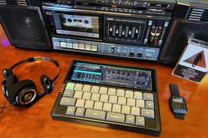
 Greg Leo
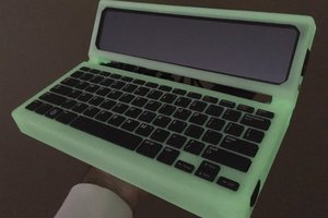
 lambtor