 BastelBaus
Some profesional and quite some DIY projects exist (link). See here my idea with a list of all core elements I plan to use to create a low cost, DIY full 6D space mouse:
- Sensors
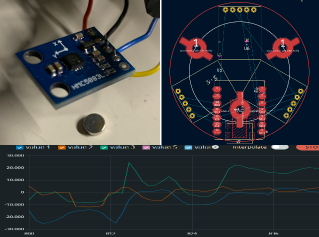
- 3x 3D magnet field sensors (QMC5883L)
- 6D IMU (MPU6050)
- 2 push buttons
- Board/Processor: Xiao ESP32S3
- dual core, up to 240MHz
- Bluetooth low energy, WiFi
- Battery management included
- USB-C
- Others
- 600mA LiPo
- 3x 2x5 round neodym magnets
- 3x 10mm (stiff) springs
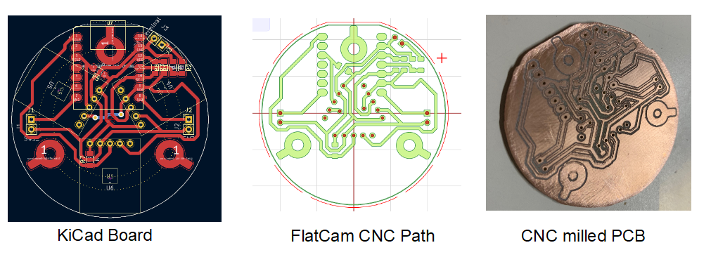
- 3D printed housing, CNC milled PCB
- Metal block for weight
- Software/Firmware
- Open Source Firmware (C++, Arduin)
- Open Source Softrware / PC driver (python)
See more on my github pages or the gitbub repository.
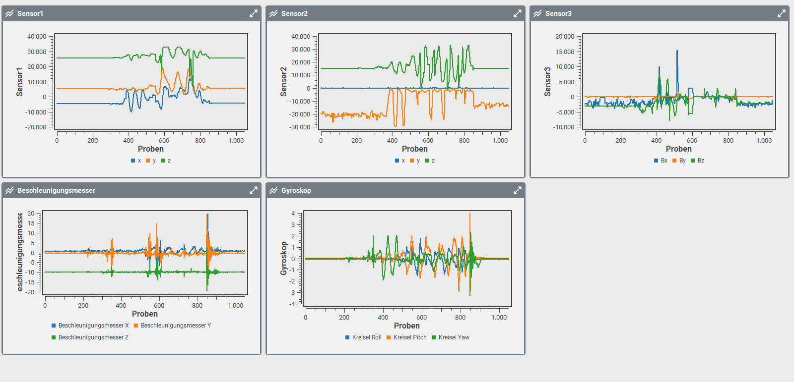
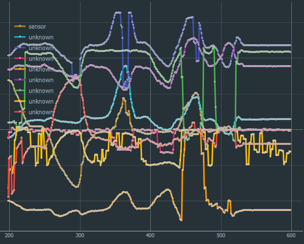
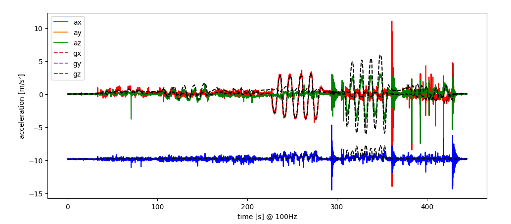 The black dashed lines are the main contribution of total measured acceleration. And even by integrating the offset compensated accelerations, the velocity and displacement had to much other effects as to see the linear displacement. With good eyes, one can see the velocity changes in the first three phases (20 ... 220s) but latest with the displacement, the integration error made everything invisible.
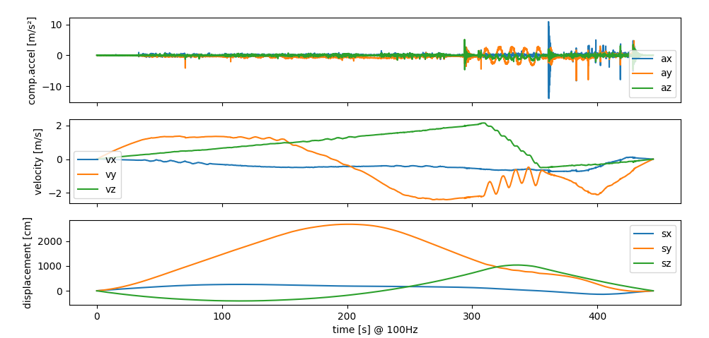 How to continue ..... don't know yet ...
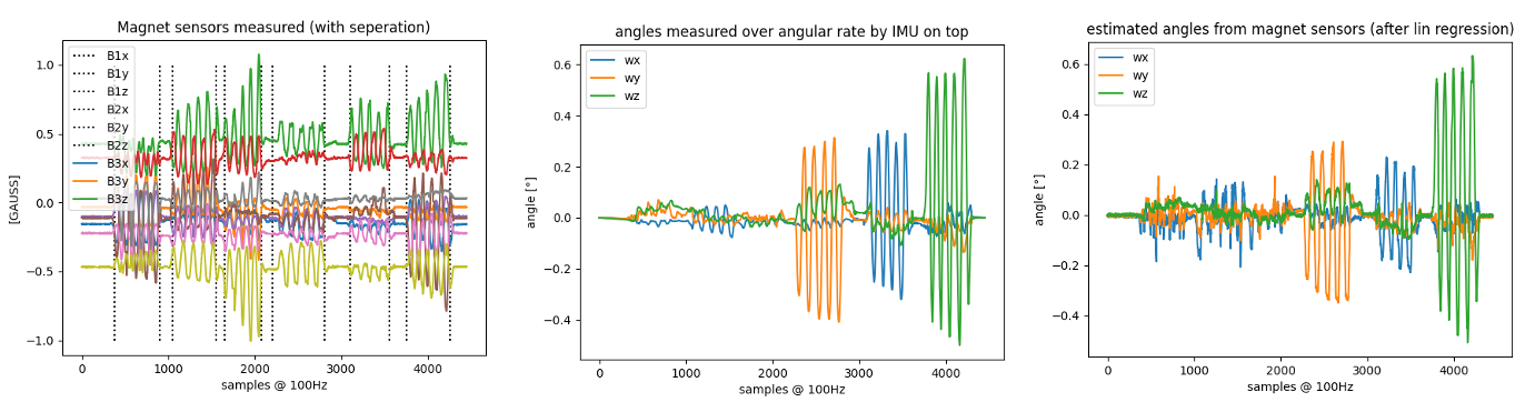 Description
 Then I used some UV curing paint to protect the copper around the spring mounts for short circuits:
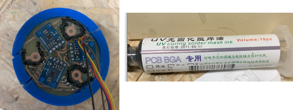
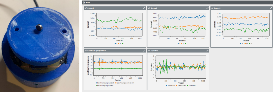 or more systematically the output of megnet sensor #1
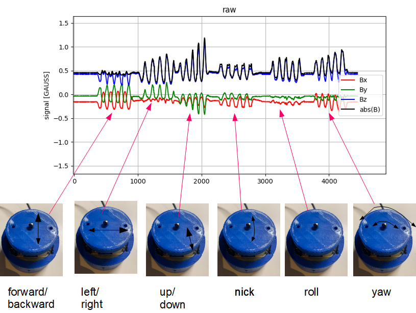
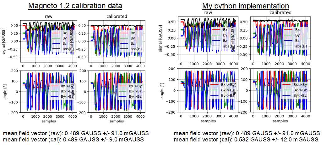
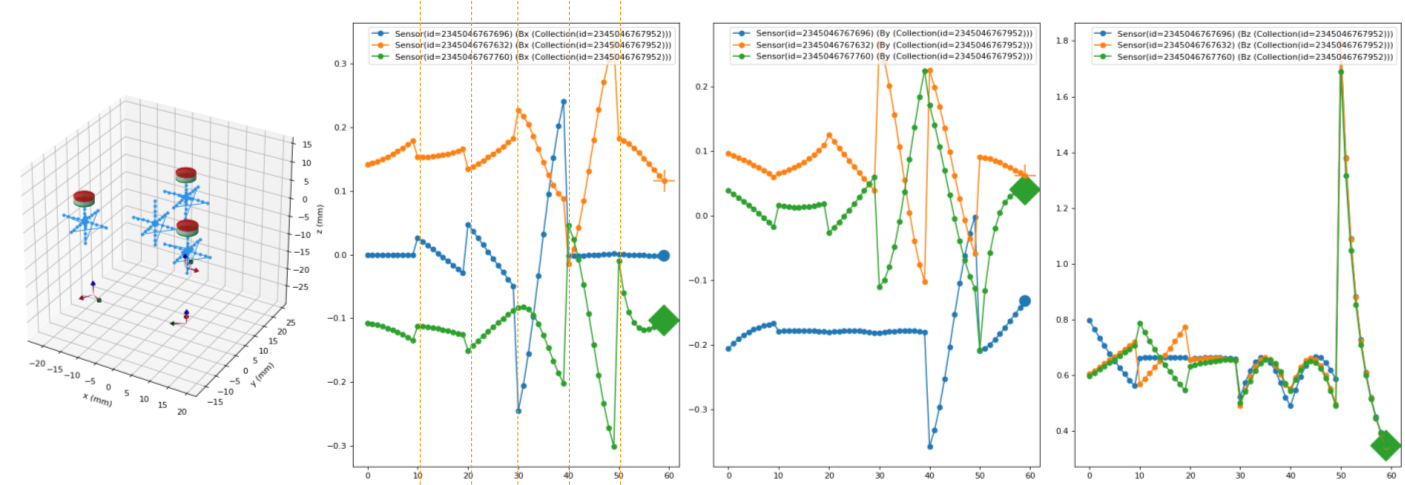
 Finally, rotating the sensors by a fixed 120° (as layouted on the PCB) gave me a very nice match:
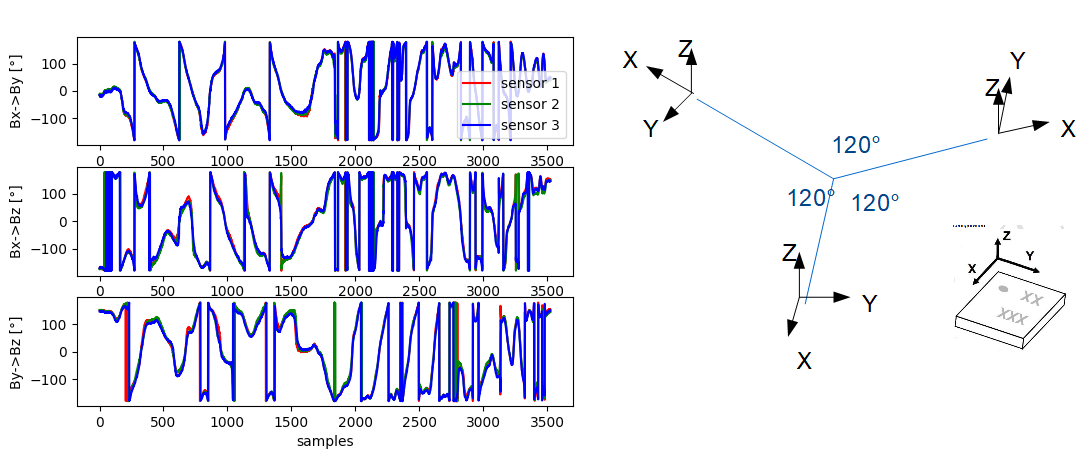
 I measured ~27s and had in total ~4200 measurement points which was above 100Hz. But since I did not take any timing measures on the ESP32 and did probably not configure the sensors correctly, I am not sure if the timing is perfect. Foir each measurement I calculated the absolute of the field vector (=sqrt(Bx^2+By^2+Bz^2)) and averaged it giving me an absolute earth magnetic field at my desk of about 0.5G (= 50uT) which seamed reasonable. The standard deviation of the measurements was <0.1G. Doing this standard deviation calculation without movement, resulted in a value <0.01G, so most of the noise resulted from the movement/timing/other effects.
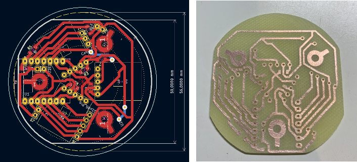 Then I designed distance blocks to let the magnetic sensors be glued to the PCB. This worked quite nice
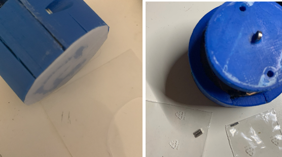
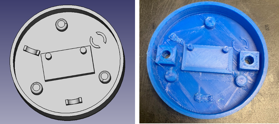
 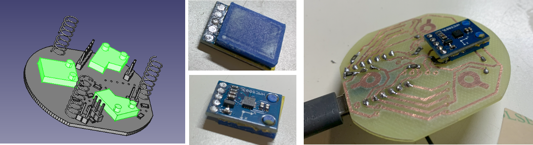 The ESP32S3 I mounted the same way, included the two wires for the battery connection (which had been rotated :-( in the design):
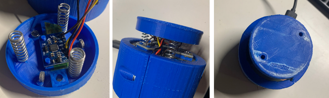
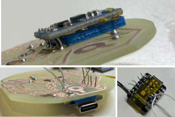 Then the base mount design followed; threaded inserts to but two half blocks together. Inside the metal weight block, the battery and on the top the PCB. The Base holds also the LED and the power switch. The push buttons and the IMU I plan to mount in the head.
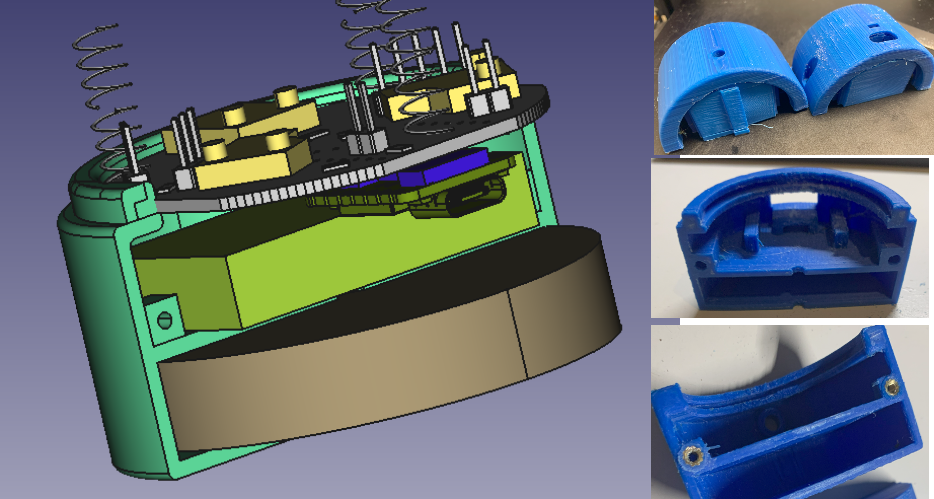 In general it worked quite good, the only problem was that the dimensions had been to small (shrinkage of the ABS I used?) and I had to print three times and still the base slightly broke. BNut sufficient to continue testing. You can see the LED in the middle picture and the battery on/off switch on the right hand side picture.
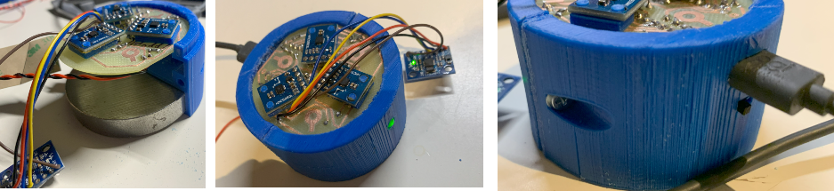 Learnings:
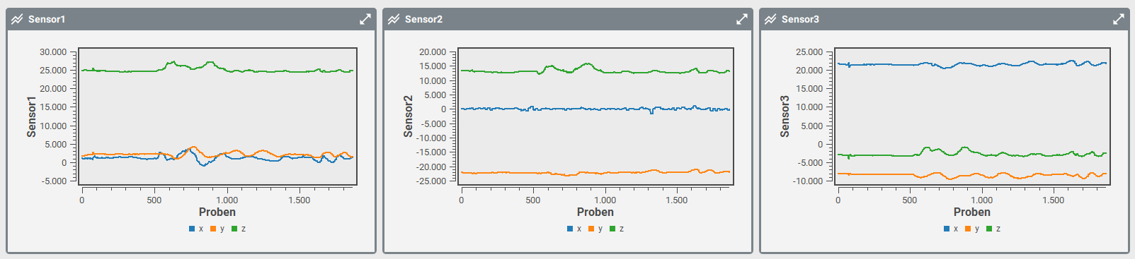 Then I printed a fast fixtured I had ten to tighten with tape. The fixture holds a 60m diameter 10mm high metal block. Fixture was not too bad, maybe a bit to stiff. I will have to design a better housing and then test again.
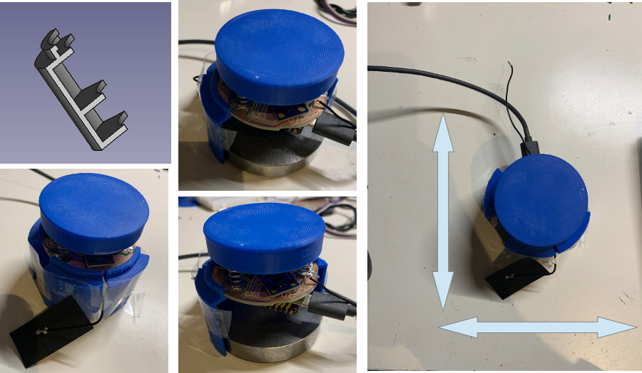 Then I did some more test, and contradictional to my first findings, there was significant less signal when I displaced the complete knob in x/y direction on the table. Only by rotating the complete knob I got some signals:
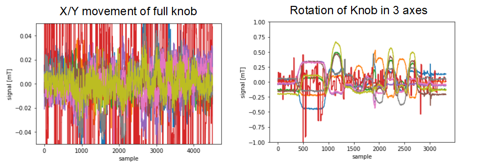 What still does not seam to be wrong is the transformation of the units. Convertig the rotation in all 3 axis I would assume to have about 30 to 60mT amplitude (the earth magnetic field. Values seamed to be much less, I might need to debug my test software here a bit more.
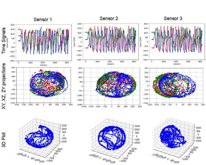
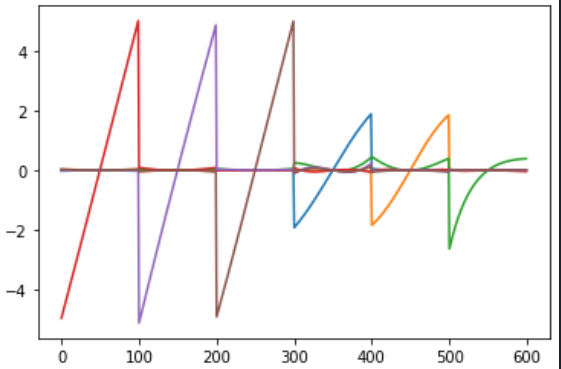
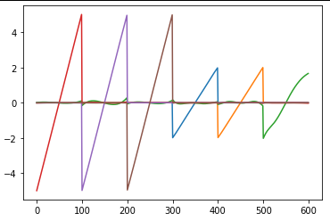
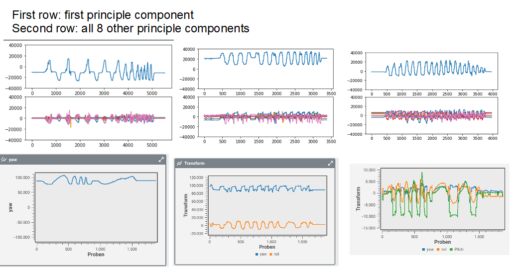 Not directly visible but I can tell you the first component (yaw) worked very nice. The plot was highly correlated to my movement of the know. When the other come in play, I recognized that there was a lot of cross talk. Then I recognized that the signal change when I move the whole know around the space ... oh yes earth magnetic field .... damn ... I plotet the raw signals from the simulation and recognized that the signals had also been in the range of the earth magnetic field (about 0.05mT):
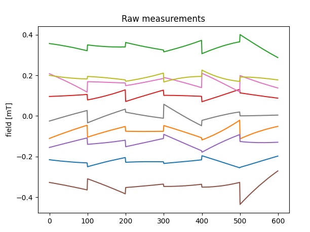
 And the 3D printed Knob with the magnets:
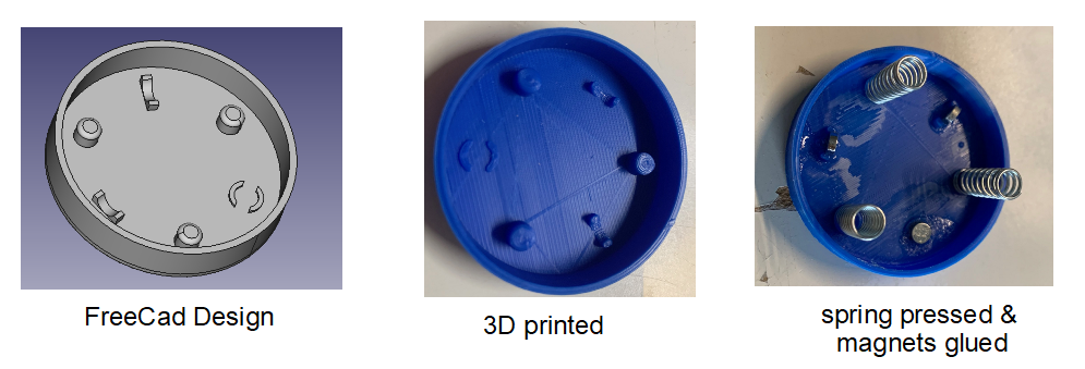 Building all together:
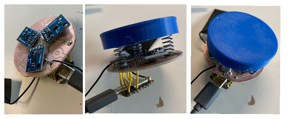
 Next steps
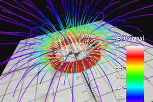
 Ted Yapo
 the.wretch
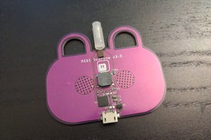
 deʃhipu
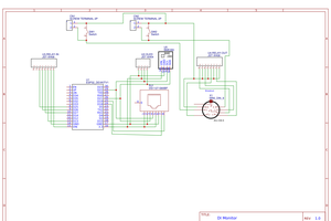
 Tim Rightnour