 Gord Payne
When the circuit detects a pack of treats at the top of the trough, it displays a cycle of orange-coloured LEDs running down the trough and plays some spooky .MP3 sounds over a set of powered computer speakers (or a HiFi) while the treats slide down to the awaiting treater.
Here are the supplies needed:
1 - Arduino microcontroller - A Nano is used here but any controller is fine.
1 - MP3-TF-16P Decoder Module and a MicroSD card - to store the spooky sound samples
1 - String of WS2812B Addressable LEDs. I'm using a 4 metre long strip with 240 LEDs. It is a 5Volt LED strip. The details are usually on the package.
1 - SR-04 Ultrasonic Distance Detector
1 - Breadboard and connecting wires.
1 - 5V, 5Amp DC power supply and a female barrel connector that matches the plug on the supply. We need AT LEAST 2Amps. More Amps is better!
1 - Piece of plastic trough. Vinyl eavestrough, PVC pipe or other options are great.
Zip ties and hot glue to fasten the LED strip to the trough.
Some plywood to support the top of the trough. Build as you see fit for your needs.
An inexpensive jack-o-lantern ornament. Optional for the mouth.
Saw horse, chair or other supports for mounting the trough.
Powered computer speakers to amplify the playing .MP3 files.
STEP 1: The WS2812B LED Strip
The WS2812B addressable LED strips are great to work with. They come in varying lengths and density of LEDs per unit of length.
Spend some time with this great tutorial to learn how we control these LEDs with the Arduino:
https://randomnerdtutorials.com/guide-for-ws2812b...
Solder some leads onto a female barrel connector so you can connect the power supply to your LED strip.
Download and install the FastLED.h library in your Documents/Arduino/Libraries folder. The link is in the article above.
Load the sample Arduino sketch into your Arduino and make sure you specify the Number of LEDs in your strip and the pin you're using for the signal.
Wire up the circuit as shown in the diagram on the website.
Double check your wiring and then plug in the power supply.
Watch the LEDs do their magic!
With LED strip working, we're ready to continue with the project.
Step 2: Build the Circuit
Follow the circuit diagram image to wire up the circuit. Since 240 LEDs were used, a lot of current is required. A 5Volt, 5Amp DC power supply was used and it's enough to power the Arduino and MP3 player as well. Each LED consumes approximately 50mA.
Double check your wiring before connecting the power supply. That's a LOT of current for a small device!
If you will be using this often, you may wish to make a more permanent soldered circuit that is more robust than the breadboard. The last image shows a permanent soldered version. The power supply feeds the 5V pin and GND pin on the Arduino directly and all the other devices receive power from these pins.
If you choose to power the LEDs AND Arduino from the same power supply, DO NOT attempt to connect the circuit to your computer with both the USB cable AND power supply connected. Disconnect the power supply before connecting to USB or you risk damaging the circuit and your computer.
STEP 3: Build the Trough
This trough is about 8 feet long so a 4 metre length of LEDs nicely covers most of the trough if you run it down one side and up the other as a single length.
There are other images of the trough, the ornaments and other parts of the project construction.
Take your string of LEDs and use hot glue or foam tape to temporarily attach it to the trough. It usually has an adhesive backing but it's more of an annoyance than it's worth. I actually removed the adhesive backing for this project.
Drill small holes through the lip of the conduit/trough along the length and then secure the LED strip to the conduit with zip ties along the length of both sides of the trough.
You'll see that there is a plywood support for the top end of the trough. It's just a piece of 5/8" ply cut with a semi-circle...
Read more »
 Coders Cafe
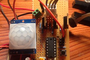
 Jeremias
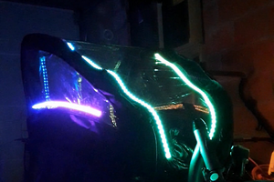
 Christoph Tack
 Enrico